manuals.online logo
Brands
  1. Home
  2. •
  3. Brands
  4. •
  5. TriangleTube
  6. •
  7. Boiler Supplies
  8. •
  9. TriangleTube CCRKIT32 User manual

TriangleTube CCRKIT32 User manual

Challenger Blower
Replacement Kit
1
WARNING
!
Indicates a potentially hazardous situation which,
if ignored, can result in
substantial property dam-
age, serious injury, or death
.
NOTICE
Indicates special instructions on installation, operation
or maintenance, which are important to equipment
but not related to personal injury hazards.
WARNING
!
For your safety, turn off electrical power supply at
service panel before proceeding to avoid possible
electrical shock hazard. Failure to do so can cause
severe personal injury or death.
WARNING
!
For your safety, the boiler may be extremely hot.
Ensure the boiler has properly cooled prior to ser-
vicing. Failure to do so can cause severe personal
injury.
WARNING
!
Failure to follow instructions below can result in
severe personal injury or damage if ignored.
• Instructions are for a qualified installer/ ser-
vice technician only.
• Read all instructions before proceeding.
• Follow instructions in proper order.
Kit Part Numbers:
• CCRKIT32: Challenger Blower Kit
Kit Includes:
1. Blower
2. Blower Outlet Gasket
3. (2) M5 Flange Nuts
4. Gas Pipe O-ring
5. Venturi Clip
Recommended Tools:
• Phillips screwdriver
• 8 mm socket and/or 8 mm wrench
• Adjustable wrench
• Pliers
• Flat putty knife
• Combustion Analyzer
Challenger Blower
Replacement Kit
2
1. Removal of Blower
1. Turn o power to the unit at the main service
switch.
2. Close the external gas shut o valve to the appli-
ance.
3. Remove the front panel by ipping down the dis-
play cover and loosening the (2) Phillips head
screws at the control panel as per Fig. 1. Pull bot-
tom of front panel forward to remove.
Fig. 1: Control Panel Screws
4. Disconnect the two wire harness plugs from the
blower motor.
BEST PRACTICE
For ease of service, remove the vent pipe between the
vent adapter and the condensate drain pan before re-
moving the blower. To remove the vent pipe, loosen the
vent pipe retaining ring attaching it to the condensate
pan then slide the pipe up and out of the condensate
pan. Pull the vent pipe out and down to remove.
5. Loosen the gas pipe brass nut at the gas valve. Set
aside the orice and o-ring for reinstallation. See
Fig. 2
Fig. 2: Gas Orice location
NOTICE
Do not discard the gas orice and gasket as they will be re-
used.
6. Remove the (2) M5 ange nuts attaching the blow-
er to the burner assembly with an 8 mm socket or
wrench.
7. Remove the blower assembly from the Challenger
by pulling downward and out.
NOTICE
If the blower gasket sticks to the burner assembly, use a at
blade putty knife to remove any gasket material. Make sure
not to scratch the mating surface on the burner assembly.
8. For Challenger models 85 and 105 only, remove the
blower orice and save to be reinstalled. See Fig. 3.
Challenger Blower
Replacement Kit
3
NOTICE
Do not discard the blower orice as it will be reused.
9. Once the blower is taken out, remove the venturi
clip on the back of the blower using pliers.
10. Remove the gas pipe & venturi assembly from the
blower inlet, See Fig. 3.
NOTICE
Note the orientation of the gas pipe and venturi before re-
moval for reassembly.
Fig. 3: Blower Assembly
* Blower orice installed in 85 and 105 only
2. Installation of Blower
1. Prior to reassembling the gas pipe and venturi into
the new blower, replace the gas pipe o-ring at the
end of the gas pipe.
2. Insert the venturi and gas pipe into the blower
housing in the proper orientation, see Fig. 4. Ensure
the venturi and gas pipe are properly seated.
3. Insert the venturi clip into the blower housing. En-
sure the venturi clip is holding the venturi and gas
pipe in place by lightly pulling on the gas pipe.
NOTICE
Do NOT force the clip into a ush t with the blower surface.
Fig. 4: Venturi assembly installation
4. Seat the blower orice (if required) and blower
outlet gasket onto the blower ange. Position the
gasket so it will allow alignment with the mounting
studs of the burner assembly.
NOTICE
Do not use any adhesive on the gasket surface during as-
sembly.
5. Install the new blower on the burner assembly us-
ing (2) M5 ange nuts.
WARNING
!
Failure to insert the gas orifice before reassembling
the gas pipe to the gas valve can result in the produc-
tion of carbon monoxide due to incomplete combus-
tion and may result in substantial property damage,
serious injury, or death.
Challenger Blower
Replacement Kit
4
6. With the gas orice in place, reconnect the gas pipe
brass nut to the gas valve. See Fig. 2.
7. If previously removed, reinstall the vent pipe.
WARNING
!
When reassembling the vent pipe, ensure all gaskets
are in place and correctly installed. Ensure all associat-
ed internal joints are complete, tight and secure. Fail-
ure to comply can result in flue gas leakage resulting
in severe personal injury.
8. Reattach the wire harness plugs to the blower mo-
tor.
9. Replace the front jacket panel and secure with the
two Phillips head mounting screws at the control
panel.
10. Open the main shuto valve to the gas supply pip-
ing. Before placing the Challenger back into service
check and test all gas piping connections for leaks.
Repair leaks if found.
WARNING
!
If any gas leaks are found or suspected, shut down the
appliance immediately. Use a gas detection device or
bubble test to locate the source of the gas leak and
repair at once. Do not operate the appliance until the
leak is corrected. Failure to comply with this proce-
dure can result in substantial property damage, seri-
ous injury, or death.
11. Turn on power at the main service switch and re-
turn to service.
12. Perform a combustion analysis by measuring CO2
or O2 and CO during both low and high ring rates.
The combustion readings must be within the range
listed in Table 1. The CO level must not exceed 100
ppm for natural gas and 150 ppm for propane gas
when combustion is correct.
Perform the following procedure to manually place
the burner into high re. Press both the “ ” and
“+”buttons simultaneously once until the operating
display shows “h” or twice until the operating dis-
play shows“H” for high re.
Perform the following procedure to manually place
the burner into low re. Press both the “ ” and
“-” buttons simultaneously until operating display
shows “L”.
Table 1: Acceptable Combustion levels
Combustion Levels Natural Gas Propane Gas
High Fire
DOOR OFF*
CO2 Range 9% - 10.1% 10.5% - 11.1%
CO2 Target 9.0% 10.8%
O2 Range 3.0% - 5% 4.1% - 5.0%
O2 Target 5.0% 4.5%
Low Fire
CO2 Range 0% - 0.4% <H.F.
9%
0% - 0.4% <H.F.
10.5% min.
O2 Range 0% - 0.6% > H.F.
5.0% max.
0% - 0.6% > H.F.
5.0% max.
CO Max. 100 ppm 150 ppm
* Door On can raise the maximum allowable CO2 by 0.4
or lower the minimum O2 by 0.6
WARNING
!
If the combustion levels are not within the range giv-
en in Table 1, shut the appliance down and contact Tri-
angle Tube Technical Support. Failure to comply with
this requirement can result in substantial property
damage, serious injury, or death.
2019-05 Challenger Blower Replacement Instructions
Revised 02/27/2019

Other TriangleTube Boiler Supplies manuals
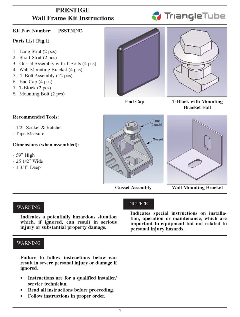
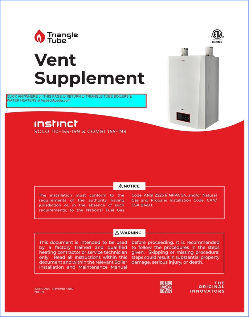
TriangleTube PSRKIT44 User manual

TriangleTube

TriangleTube PSRKIT44 User manual

TriangleTube PGRKIT25 User manual

TriangleTube

TriangleTube PGRKIT25 User manual

TriangleTube Instinct SOLO 155-199 User manual

TriangleTube

TriangleTube Instinct SOLO 155-199 User manual

TriangleTube PSRKIT53 User manual

TriangleTube

TriangleTube PSRKIT53 User manual

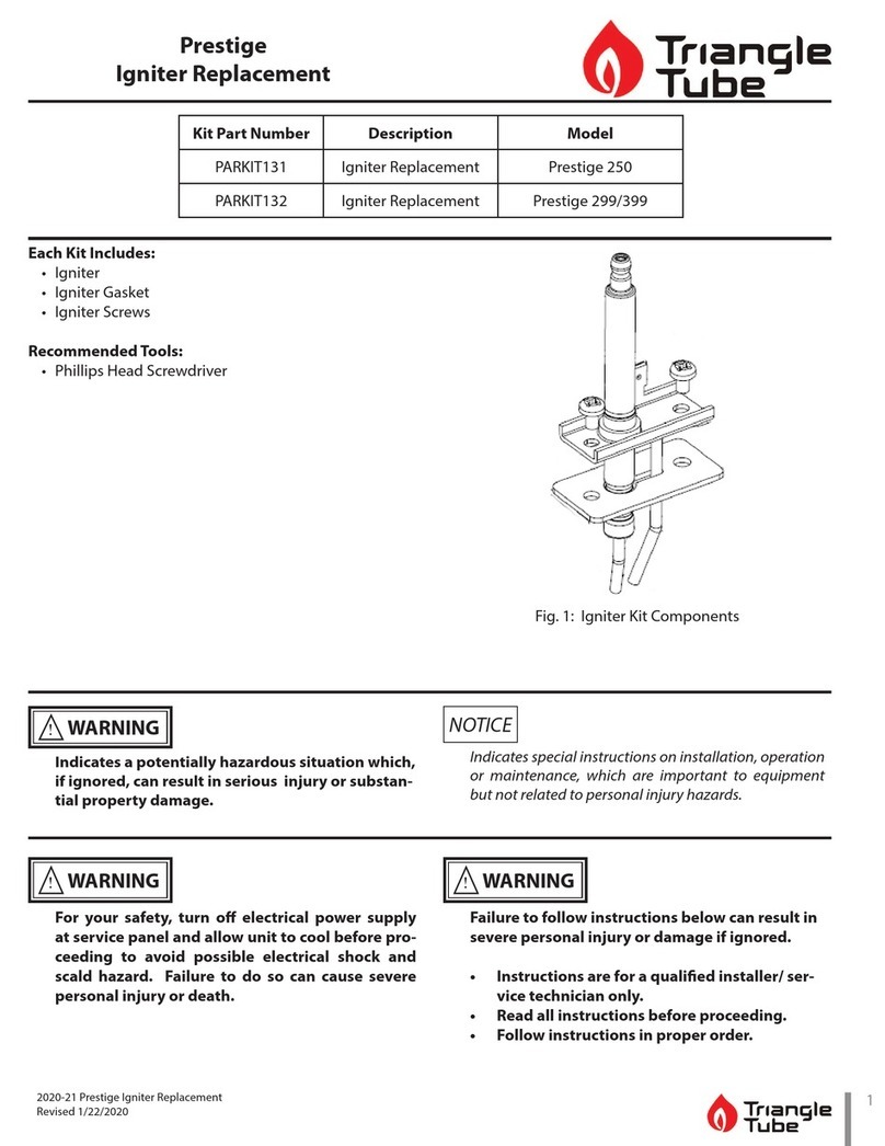
TriangleTube PARKIT131 Use and care manual

TriangleTube

TriangleTube PARKIT131 Use and care manual

TriangleTube PGRKIT30 User manual

TriangleTube

TriangleTube PGRKIT30 User manual

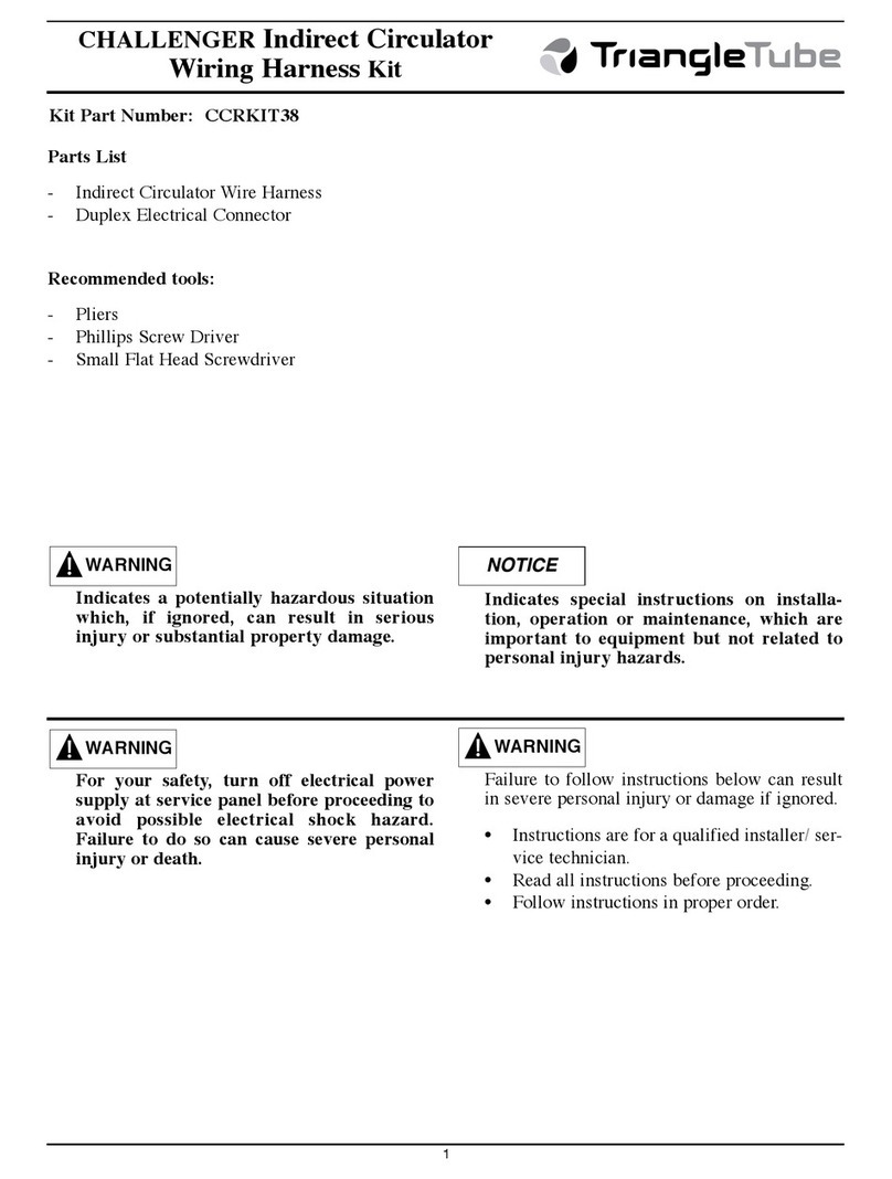
TriangleTube CHALLENGER CCRKIT38 User manual

TriangleTube

TriangleTube CHALLENGER CCRKIT38 User manual

TriangleTube PSRKIT80 User manual

TriangleTube

TriangleTube PSRKIT80 User manual

TriangleTube PSRKIT51 User manual

TriangleTube

TriangleTube PSRKIT51 User manual

TriangleTube PSSTND02 User manual

TriangleTube

TriangleTube PSSTND02 User manual
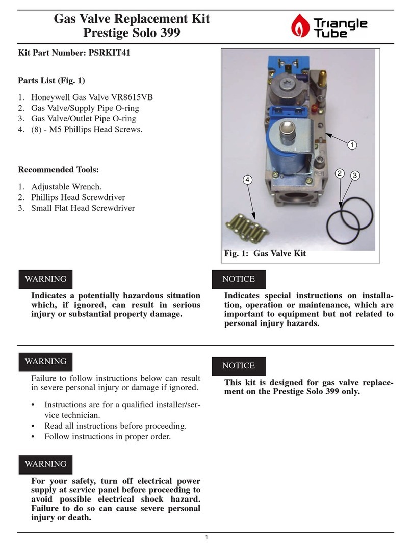
TriangleTube PTRKIT304 User manual

TriangleTube

TriangleTube PTRKIT304 User manual

TriangleTube PSRKIT84 User manual

TriangleTube

TriangleTube PSRKIT84 User manual

TriangleTube PTRKIT305 User manual

TriangleTube

TriangleTube PTRKIT305 User manual

TriangleTube PSRKIT36 User manual

TriangleTube

TriangleTube PSRKIT36 User manual

TriangleTube PSRKIT19 User manual

TriangleTube

TriangleTube PSRKIT19 User manual

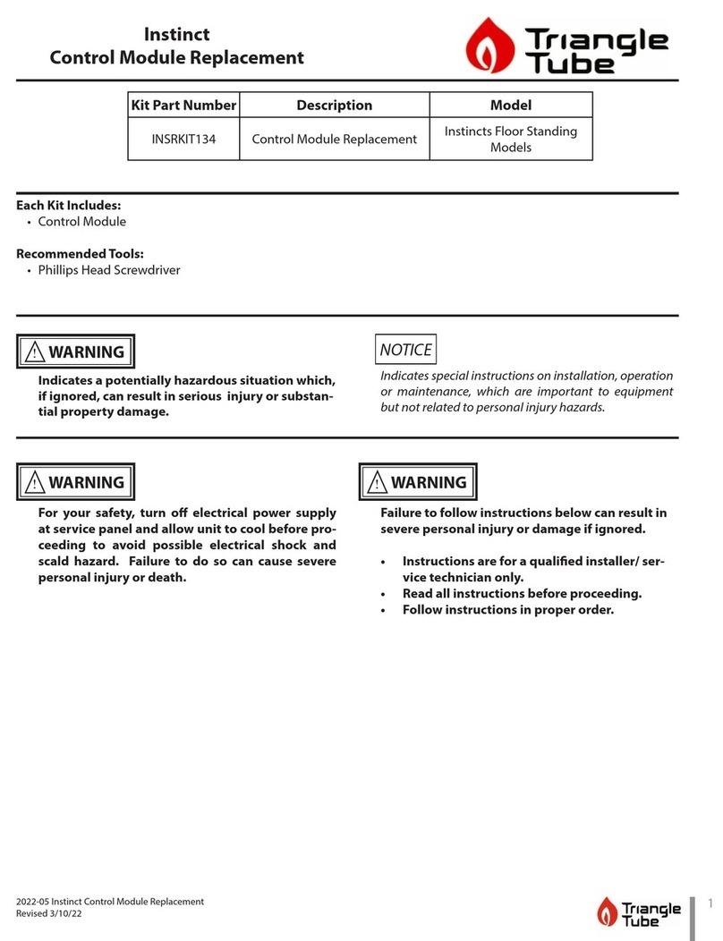
TriangleTube Instinct INSRKIT134 Use and care manual

TriangleTube

TriangleTube Instinct INSRKIT134 Use and care manual

TriangleTube PSRKIT41 User manual

TriangleTube

TriangleTube PSRKIT41 User manual
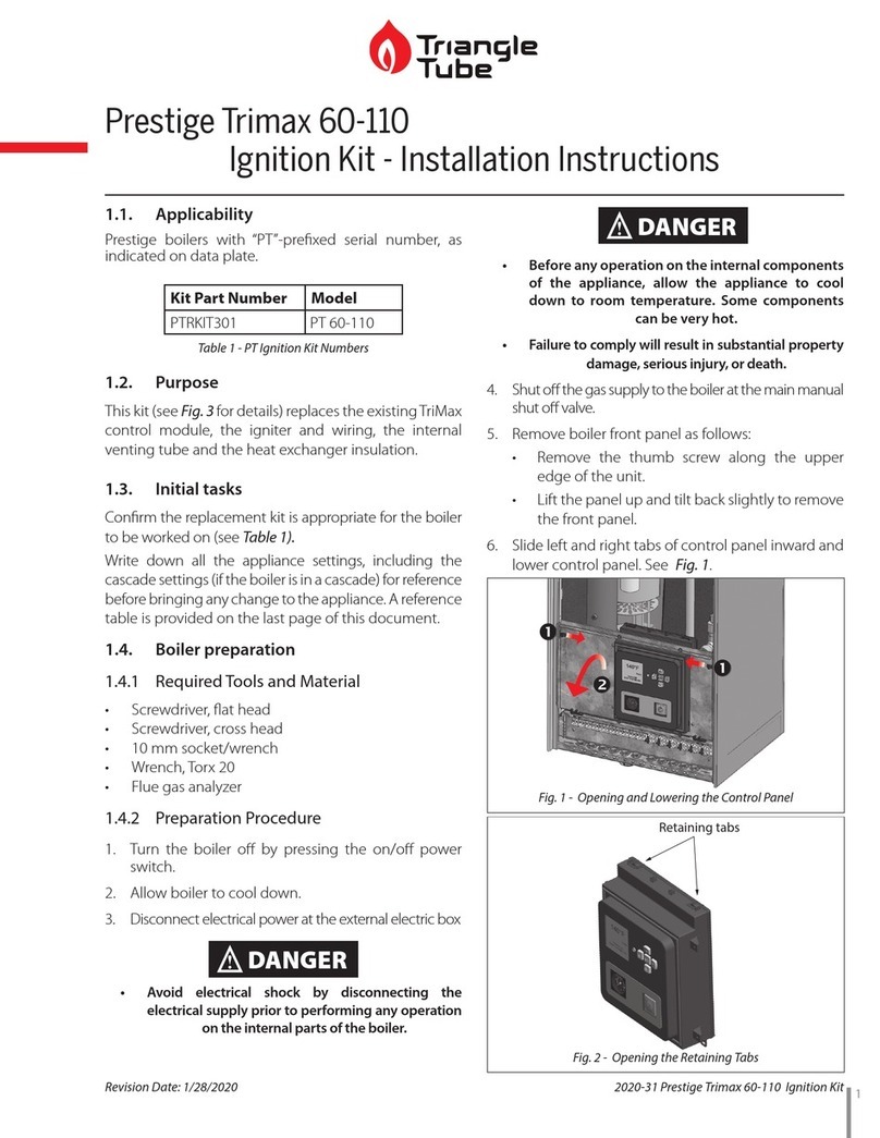
TriangleTube PTRKIT301 User manual

TriangleTube

TriangleTube PTRKIT301 User manual
Popular Boiler Supplies manuals by other brands
Grunbeck GENO-Neutra FNH-420-R Operation manual

Grunbeck

Grunbeck GENO-Neutra FNH-420-R Operation manual

Z Boiler Miura ML2-200 Operation manual

Z Boiler

Z Boiler Miura ML2-200 Operation manual

IBC P-153B Replacement instructions

IBC

IBC P-153B Replacement instructions

Ecotermal 6 MRT Assembly and operation manual

Ecotermal

Ecotermal 6 MRT Assembly and operation manual

Riello ITRF 11 quick start guide

Riello

Riello ITRF 11 quick start guide

manuals.online logo
manuals.online logoBrands
  • About & Mission
  • Contact us
  • Privacy Policy
  • Terms and Conditions

Copyright 2025 Manuals.Online. All Rights Reserved.