Getinge 88-SERIES User manual

GETINGE 88-SERIES
INSTALLATION MANUAL
502404200
SEV0647139-

<Doc_INS><Doc_502404200><Rel_A><Lang_GB>
Page 2 of 24
Contents
FOREWORD ____________________________________________3
SAFETY REGULATIONS _________________________________4
Important _________________________________________________ 4
The machine must be assembled and installed: ________________ 4
When the work is complete, check that _______________________ 5
Product liability ____________________________________________ 5
Isolator switch _____________________________________________ 5
Attention symbols __________________________________________ 5
INSTALLATION__________________________________________6
Wall-mounted model________________________________________ 7
Fitting AGS ________________________________________________ 7
Connecting electric power___________________________________ 8
Connecting water, steam, waste and dryer ____________________ 11
Model identification_________________________________________ 14
Function check ____________________________________________ 15
TECHNICAL DATA_______________________________________16
Water quality - washer disinfectors_______________________20

Page 3 of 24
<Doc_INS><Doc_502404200><Rel_A><Lang_GB>
FOREWORD
This instruction manual is intended for users of the Getinge washer disinfector 88-5.
The instruction manual describes the design and operation of the machine and the main-
tenance for which the user is responsible. The purpose of the information in the manual
is to ensure safe operation and optimum efciency.
Before using the machine for the rst time, users must have read this instruction manual
and familiarized themselves with the operation of the machine and its safety instructions.
Read through the instruction manual before using the machine.
The information in this manual describes the machine as dispatched from Getinge.
There may be differences due to customization.
The machine is accompanied by the following documentation:
User manual
Installation instructions (this manual)
Technical manual
Spare parts list
Goods positioning instructions
The Goods positioning instructions supplied must be put up in a clearly visible position
at the time of installation.
Getinge reserves the right to change the specication and design without prior notice.
The information in this manual was up to date on the date of issue of the manual.
•
•
•
•
•
© Copyright
The content of this manual must not be copied, in
whole or in part, without the written consent of Getinge.

<Doc_INS><Doc_502404200><Rel_A><Lang_GB>
Page 4 of 24
SAFETY REGULATIONS
This machine has been designed with a number of built-in safety devices. To avoid in-
jury, it is highly important not to bypass or disable these safety devices.
If the equipment is used in a manner not specied by the manufacturer this can impair
the safety equipment on the machine.
Operators and maintenance personnel must undergo safety training for the machine.
All personnel who handle chemicals for washing and disinfection must understand the
washing process, possible health hazards and ways of detecting leaks of toxic chemicals.
Operators and maintenance personnel must undergo regular training in the operation and
maintenance of the equipment. There must be a documented list of personnel who have been
trained on the machine. Trained personal must be tested to verify the training programme.
Important
Take care when handling the chemical agents used in the machine.
Read the instructions on the pack or contact the manufacturer before using the ma-
chine for instructions about:
- what to do if the substance comes into contact with the eyes or skin or if
vapors are inhaled.
- storage of packs and sorting of empty packs for disposal.
The machine must be connected in accordance with the instructions given in the instal-
lation manual.
The machine may only be used by adults.
Installation and servicing may only be done by personnel trained for this machine.
Never bypass door safety switches.
Leaks in the system caused by worn seals in the door, for example, must be re-
paired immediately.
Before doing any repair or servicing work, the personnel concerned must study the
relevant handbooks and service manuals.
Before any welding is done, all cables connected to the control system via connec-
tors and sockets must be disconnected.
Before doing any servicing or maintenance work on the machine, isolate it from the
electric power supply and drain all tanks.
Do not wash down or hose down the machine with water.
Take care when using corrosive substances.
Observe safety measures for steam and hot water.
The machine must not be operated with cladding plates, roof and plinths removed.
Doing this puts at risk the safety and functioning of the machine.
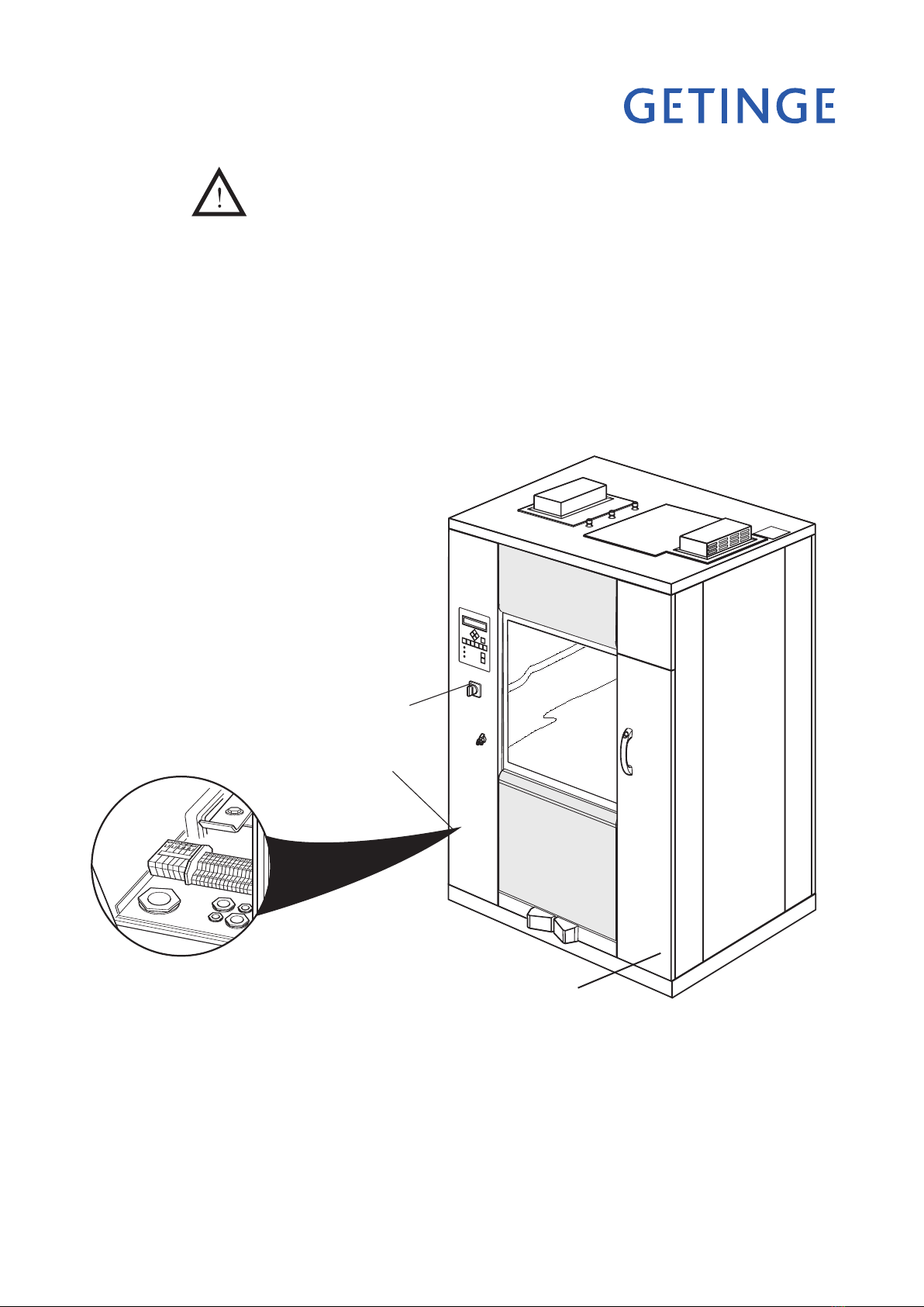
The electrical cabinet may only be opened by authorized and trained personnel.
Spare parts may only be obtained from Getinge EDC.
The machine must be assembled and installed:
by qualied personnel.
in accordance with current local regulations and rules.
Warning!
To avoid the risk of back injury, this equipment should be assembled and
installed by two people.
•
•
•
•
•
•
•
•
•
•
•
•
•
•
•
•
•
•

Page 5 of 24
<Doc_INS><Doc_502404200><Rel_A><Lang_GB>
When the work is complete, check that
all parts have been installed in accordance with the installation instructions
all screws have been properly tightened
there are no sharp edges on any parts that may come into contact with people
all hoses, pipes and connections are intact and free from defects
all the functions of the machine are working properly. Adjust if necessary.
Carry out an Installation Qualication, an Operating Qualication and a Performance
Qualication according to ISO 15883 before putting the machine into service.
Incorrect use can result in damage to objects and personal injuries
Product liability
Any modication or incorrect use of the equipment without the approval of
Getinge Disinfection AB invalidates Getinge Disinfection AB´s product liability.
This product was manufactured by:
GETINGE DISINFECTION AB
Ljungadalsgatan 11, Box 1505
351 15 Växjö, Sweden
Isolator switch
The machine must be tted with a separate, lockable isolating device in the electric pow-
er supply. The isolating device must be easily accessible on a wall close to the machine.
The installation must conform to and be marked in accordance with local provisions.
Attention symbols
Some of the warnings, instructions and advice in this manual are so important that we
use the following special symbols to draw attention to them. The symbols used are as
follows:
This symbol indicates a warning in the text of the manual. It warns of a hazard
that may lead to more or less severe injury and in certain cases mortal dan-
ger. It also highlights warnings to avoid damage to equipment.
•
•
•
•
•

<Doc_INS><Doc_502404200><Rel_A><Lang_GB>
Page 6 of 24
INSTALLATION
The oor where the machine is to stand must be at and level within ±5 mm.
Pull the machine (on a transport pallet) to the location where it will be installed.
Lift the machine off the pallet.
Position the machine at the chosen location and adjust the feet so that the machine
is stable.
Adjust the loading cart docking system vertically and laterally so that it ts with the
cart.
•
•
•
•
•
Base frame
V318b
Figure 1. Adjustment
Using a spirit level, check as shown in Figure 1 that the machine is level within ±2 mm.
If you need to move the machine by using a pallet truck:
Position the pallet truck forks as shown in Figure 2 so as not to damage the machine.
•
•
Figure 2. Positioning the pallet truck forks.
Level the
machine with
a spirit level.
J031
J032
Foot plate
Adjusting screw
Docking
J205

Page 7 of 24
<Doc_INS><Doc_502404200><Rel_A><Lang_GB>
Wall-mounted model
If the machine is to be mounted in a wall, the distance between machine and wall
must be 15 mm.
If machines are to be installed next to each other they must be adjusted to the same
height on installation.
Set the machine horizontal with a spirit level on the side of the machine and adjust
with the feet.
For the loading trolley to work in all the machines, the oor in front of them must
be at and level.
Fitting AGS
When AGS is installed, the plinth plate must be removed, since it is replaced by a
plinth plate in the AGS installation.
Service panels on the roof must be removed and any water connections disconnected
so that they can be temporarily lowered into the roof panel to reduce the height of
the machine.
•
•
•
•
•
•
Figure: dimensions
J033
Service area

<Doc_INS><Doc_502404200><Rel_A><Lang_GB>
Page 8 of 24
Connecting electric power
Installation may only be done by authorized personnel.
Connect electric power to the machine as follows:
Connect the power supply to the electrical connections of the machine; see the dia-
gram with alternative connection arrangements.
For easier servicing and maintenance, the supply to the machine should be tted
with a lockable isolator with a 3 mm break gap.
The isolator must be located in an easily accessible position on the wall.
The supply cable must be brought in through a hole in the side, tted with a rubber
seal. The side has two holes, one on the left and one on the right.
Remove the Plexiglas cover over the incoming side of the terminal block. Ret the
Plexiglas cover when the connections have been made.
The supply cable and any signal cables must be provided with strain relief by
means of the cable glands at the bottom of the electrical cabinet.
The power supply cable to the machine must be connected to the incoming terminal strip
-X01. The protective ground (earth) wire must be connected to the terminal marked with
the protective ground (earth) symbol in terminal strip –X01.
Smallest cable area for power supply.
Steam.
Incoming terminal strip –X01 can take cables with conductor area between
AWG16-8 (1.5 – 10 mm2).
The area of the supply cable must not be less than AWG 10 (6 mm2). Its diameter must
not be less than Ø 18 mm.
Electrical
Incoming terminal strip –X01 can take cables with conductor area between
AWG16-8 (1.5 – 10 mm2).
The area of the supply cable must not be less than AWG 8 (10 mm2). Its diameter must
not be less than Ø 21 mm.
Residual current device (RCD)
The machine is tted with a frequency converter to control the rotation speed of the
circulation pump. If there is an RCD in the power supply line to the machine, the RCD
must be designed to protect equipment with a frequency converter.
•
•
•
•
•
•
•

Page 9 of 24
<Doc_INS><Doc_502404200><Rel_A><Lang_GB>
It is important that the connection has the correct overcurrent protection.
The correct fuse rating is stated on the type plate.
The main switch on the front of the machine disconnects the power to all components
connected to the machine that are connected after the main switch of the machine.
Cables for signal exchange may also be connected to the machine. These cables are
connected to terminal strips X04 (dosing monitoring), X06 (signal exchange) and X07
(loader/unloader and AGS). When the cables have been connected, the Plexiglas shield
that provides protection between terminal strip X01 and terminal strips X04-X07 must
be put back in place.
See the technical manual for additional information.
Main switch
Electrical
connection
Figure 4 Electrical connection (see alternative connection arrangements)
Type plate
on the inside
J034
V2033

<Doc_INS><Doc_502404200><Rel_A><Lang_GB>
Page 10 of 24
200-240 V, 3+PE 50/60 Hz
-X01
Supply cable
380-415V, 3N+PE 50/60 Hz
-X01
Supply cable
NL3L2
L1 L3L2L1
-X01 terminal strip for incoming supply cable
Electrically-heated chamber and electrically-heated dryer
Voltage
[V]
Connection
Frequency
[Hz]
Max current
[A]
Fuse
[A]
380 3+PE 50/60 34 C40
400 3N+PE 50/60 35 C40
415 3N+PE 50/60 36 C40
Steam-heated chamber and electrically-heated dryer
Voltage
[V]
Connection
Frequency
[Hz]
Max current
[A]
Fuse
[A]
200 3+PE 50/60 25 C32
208 3+PE 50/60 24 C30
230 3+PE 50/60 22 C25
240 3+PE 50/60 21 C25
380 3+PE 50/60 14 C20
400 3N+PE 50/60 14 C20
415 3N+PE 50/60 14 C20

Page 11 of 24
<Doc_INS><Doc_502404200><Rel_A><Lang_GB>
Connecting water, steam, waste and dryer
Installation may only be done by authorized personnel.
Provide water and, if required, steam connections with separate stopcocks. Flush
out the water and steam pipes that are to be connected to the machine, to prevent
clogging of lters and valves.
Connect the disinfector to cold and hot water and to steam and condensate connec-
tions, if used. The connections must meet the following requirements:
•
•
Connection Pressure Flow rate
Cold water ISO G-3/4” (20 mm) female 100-800 kPa min 40 l/min
Hot water ISO G-3/4” (20 mm) female 100-800 kPa min 40 l/min
Dist. water/
de-ion. water ISO G-3/4” (20 mm) male 100-800
kPa* min 40 l/min
Steam ISO G-1/2” (15 mm) female 300-500 kPa
Condensate ISO G-1/2” (15 mm) female max 30 kPa
Compressed air ISO G-1/2” (15 mm) female 400-800 kPa
* Where the pressure is lower than 100 kPa a separate feeder pump must be used.
NOTE:
Distilled or de-ionised water must have a conductivity of less than 40 µS/cm.

<Doc_INS><Doc_502404200><Rel_A><Lang_GB>
Page 12 of 24
CW. Cold water 450 mm above the oor
HW. Hot water 450 mm above the oor
DW. Distilled/de-ionized water 450 mm from oor
Ex. Dryer exhaust air at roof
E. Electrical connection 370 mm from oor
S. Steam connection 60 mm above the oor
C. Condensate connection, 30 mm above oor
D. Waste connection 175 mm above the oor
Floor connection
J035b
Figure 5. Connections

Page 13 of 24
<Doc_INS><Doc_502404200><Rel_A><Lang_GB>
Ceiling connection
CW. Cold water 1905 mm above the oor
HW. Hot water 1905 mm above the oor
DW. Distilled/de-ionized water 1905 mm from oor
Ex. Dryer exhaust air at roof
E. Electrical connection 350 mm from oor
S. Steam connection 1830 mm above the oor
C. Condensate connection, 1830 mm above oor
D. Waste connection 175 mm above the oor
Figure 6. Connections

<Doc_INS><Doc_502404200><Rel_A><Lang_GB>
Page 14 of 24
PTFE tape is recommended for sealing the connections.
Connect the disinfector to a waste outlet with a capacity of at least 40 litres/min.
Connect the waste as shown in Figure 5. Diameter of waste: 50 mm (2”).
Where the washer disinfector is installed against a wall, or where two machines are
positioned next to each other, Getinge recommends leaving a 500 mm service area.
•
•
•
Figure 7. Connecting a dryer
Connect air exhaust from dryer (if the machine has a dryer)
Air volume: approx 350 m3/h.
Model identification
The rating plate for an 88-5 washer disinfector is located in the detergent compartment.
Make a written note of the type designation and serial number (No.) from the rating plate.
Type:______________________________________
Serial number:______________________________
When contacting Getinge, quote the model type and serial number.
•
J036b

Page 15 of 24
<Doc_INS><Doc_502404200><Rel_A><Lang_GB>
Function check
Check that the machine is connected to the correct voltage and the waste, water,
steam and condensate connections are correctly connected. Open the valves for
water and steam.
Fill the detergent and rinse aid containers and place alarm sensors in the containers.
When starting a new machine, the soiled-side door can be opened and closed by
holding down the U button for about ve seconds.
The doors of the machine have a system of interlocks to ensure that only one door
can be opened at a time.
The clean-side door can only be opened if the completed process has been ap-
proved and the soiled-side door is closed and locked.
If the soiled-side door cannot be opened, check that the clean-side door is closed
and locked. If not, close the door by pressing W.
Place a wash rack in the wash chamber and close the door.
Choose a program where dosing is done from all the detergent and rinse-aid con-
tainers and start the machine (see the instruction manual).
Check that the machine draws water.
Note!
On starting, there must be water in the circulation pump. If there is no water in the pump
the shaft seal may be damaged.
Check that the circulation pump is rotating in the right direction as indicated by the arrow
on the pump motor. If not, isolate the power, change the phase sequence at the electrical
connections and restart the machine (see the service manual for a detailed description).
•
•
•
•
•
•
•
•
•
•
Figure 8. Circulation pump
Check that the dosing pumps work at the right time in accordance with the program
description in the instructions for use and that detergent is drawn off.
While the program is running, check that the door(s) cannot be opened.
Check that there are no water or steam leaks. If necessary, retighten water, steam
and waste connections.
•
•
•
V766

<Doc_INS><Doc_502404200><Rel_A><Lang_GB>
Page 16 of 24
TECHNICAL DATA
Dimensions
Outside dimensions
Width 1270 mm
Depth 990 mm
Height 1870 mm
Chamber, effective dimension
Chamber depth 800 mm
Chamber width 665 mm
Chamber height 667 mm
Chamber volume 340 litres
Material EN1.4404, ASTM 316L
Weight including water and load.
Total 600 kg
Loading per machine foot 150 mm (four).
Specic area loading 4.7 kN/m2
Connections
Water consumption
40 l/phase pre-rinsing and washing Note 1.
32 l/phase post-rinsing and nal rinsing Note 1.
Cold water
Recommended water quality: Drinking water with max 5°dH
Connection ISO G-3/4
Pressure 100-800 kPa
Flow rate 40 litres/min
Hot water
Recommended water quality: Preheated drinking water with max 5°dH
Recommended temperature < 20°C (<68°F) Note 2.
Connection ISO G-3/4
Pressure 100-800 kPa
Flow rate 40 litres/min
Distilled/de-ionized water (option)
Recommended water quality: The maximum conductivity is determined by the desired wash-
ing result.
Max temperature 60°C (140°F) Note 2.
Connection ISO G-3/4
Pressure 100-800 kPa (where the pressure is lower than 100 kPa, a sepa-
rate pressure booster pump must be connected. This is available
as an option.)
Flow rate 40 litres/min
Note 1. The water consumption varies depending on the type of wash trolley and the items.
Note 2. The water temperature affects the process time. A lower temperature gives a longer process.

Page 17 of 24
<Doc_INS><Doc_502404200><Rel_A><Lang_GB>
Compressed air (option with loader/unloader only)
Connection pressure 400-800 kPa
Steam (only for a machine with steam-heated chamber)
Connection ISO G-1/2
Pressure 300-500kPa Notes 3, 4.
Max steam temperature 160 °C (320 °F)
Consumption about 1.5 kg/min at 300 kPa
Steam (only for a machine with steam-heated chamber)
Connection ISO G-1/2 Note 4.
Waste outlet
Dimension, out ø75 mm (3”)
Minimum capacity of receiving drain
1. Capacity 50 l/min, Max 90 °C (194 °F)
2. Capacity with drain cooling (option) 90 l/min, max 60 °C (140 °F)
Recommended connection dimension >100mm (>4 In)
Evacuation air
Air quantity about 350 m3/h Note 5
Max temperature: 50°C (50.00°C)
Air humidity 20-100 % Note 6
Note 2. The water temperature affects the process time. The lower the water temperature, the
longer the process will take.
Note 3. The pressure and temperature of the steam affect the process time. The lower the pres-
sure, the longer the process will take.
Note 4. The pressure differential between the supply and return lines must be greater than 100 kp.
Note 5. The connection to the machine must have an air gap of 50 mm.
Note 6. The exhaust air from the dryer must have 100% humidity not more than 5 minutes after
the dryer is started.

<Doc_INS><Doc_502404200><Rel_A><Lang_GB>
Page 18 of 24
Environmental requirements
Air humidity max 80% at 31 °C (87 °F)
Room temperature 5-40 °C (41-104 °F)
Heat dissipation to the room
Max 6000 W hot air during drying.
Max 1500 W during disinfection at 90 °C (194 °F)
Max external temperature of the machine 50 °C (123 °F)
Sound level
Table 1 below shows the sound power level as linear octave band values and as co-weighted, A-
weighted sound power level, both equivalent L wA and maximum LwAFmax.
Table 1
Calculated sound power level Lw for the test object, db ref 1 pW.
Octave band frequency (Hz) 125 250 500 1000 2000 4000 8000 LwA LwAFmax
Correction terms (Kok) 65 66 67 63 63 60 58 70 76
The calculated sound power level implies different sound levels LpA in different types of space.
With a larger room volume, the sound level decreases slightly and with a smaller room level it
increases slightly. Table 2 below shows three example of what to expect in practice.
Table 2
Calculated sound level LpA for the test object in a 70m3 room, db ref 20 µPa.
Type of room Description Operator
position*
3 meters from
the machine
Hard to sound All surfaces of tile, plaster, concrete or
similar, i.e. no sound absorbing surfaces
and no furniture
69 69
Normally-damped Some sound absorption in the form of
furniture and textiles.
65 64
Damped Full-cover ceiling absorbent and some
furnishing with tables, chairs and textiles.
62 60
* The term “operator position” means 1 meter from the machine and 1.5 meters above the oor.
All the gures are for one machine.
Degree of protection
IP21

Page 19 of 24
<Doc_INS><Doc_502404200><Rel_A><Lang_GB>
Other points
Circulation system
Design pressure: 300 kPa
Working pressure: max 130 kPa
Design temperature 100°C (100.00°C)
Working temperature 93°C (92.78°C)
Material: EN1.4404, ASTM 316L
Waste tank
Type of vessel: not closed
Material: polypropylene
Volume 50 litres (13.21 gallons)
Max temp 95 °C (203 °F)
Process tank
Type of vessel: not closed
Material: polypropylene
Volume 50 litres (13.21 gallons)
Max temp 95 °C (203 °F)
Booster tank
Type of vessel: not closed
Material: EN1.4404 ASTM 316L
Volume 35 litres (9.24 gallons)
Max temp 99°C (98.89°C)
Circulation pump
Flow rate: Q max 1000 litres/min
Power: 2.2 kW
Material:
Pump body: EN1.4404, ASTM 316L
Pump impeller PP
Drain pump
Flow rate: Q max 50 litres/min
Power: 170 W
Material:
Pump body: PP
Impeller: PP

<Doc_INS><Doc_502404200><Rel_A><Lang_GB>
Page 20 of 24
Water quality - washer disinfectors
The quality of the water used in all stages of cleaning is important for good results.
The water used in each stage must be compatible with:
* The material of which the washer disinfector is made
* The chemicals used in the process
* Process requirements for the various stages of the process
The main factors for good water quality are:
Hardness High hardness will cause lime scale deposits in the washer disinfector,
leading to poor cleaning results.
Ionic contaminants A high concentration of ionic contaminants may cause corrosion and pitting
on stainless steel.
Heavy metals such as iron, manganese or copper cause instruments to
tarnish.
Microbial contaminants The water used should not increase the biological load on the equipment
that is being treated against micro-organisms and their residual products
which may cause fever-like symptoms when they get into the human body.
Sanitary chemicals High concentrations of and high exposure to sanitary chemicals may cause
corrosion and pitting on stainless steel.
Getinge Disinfection AB therefore recommends that water used in the pre-rinsing, washing
and nal rinsing phases should be of drinkable quality in accordance with the guidelines.
Detailed information about acceptable water quality can be found in “Guidelines for
Drinking Water Quality 3rd Edition” published by WHO.
Getinge Disinfection AB also recommends following local standards. RO (reverse-
osmosis)water (or similarly treated water) is used for the nal washing/disinfection phase.
A typical specication for RO water is:
pH 5.5 to 8
Conductivity <30 µs.cm-1
TDS <40 mg/l
Maximum hardness <50 mg/l
Chlorine <10 mg/l
Heavy metals <10 mg/l
Phosphates <0.2 mg/l as P2O5
Silicates <0.2 mg/l as SiO2
Endotoxins <0.25 EU/ml
Total number of micro-organisms <100 per 100 ml
Further advice should also be obtained from the manufacturers of chemical and medical
equipment.
Where local standards are stricter that Getinge Disinfection AB’s recommendations, they
should be followed. Note that it is the customer’s responsibility to supply the washer
disinfector with suitable water.
Other manuals for 88-SERIES
2
This manual suits for next models
1
Table of contents
Other Getinge Cleaning Equipment manuals

Getinge
Getinge S-606 User manual

Getinge
Getinge Castle 7900 User manual

Getinge
Getinge 46-2 User manual

Getinge
Getinge 86 SERIES User manual

Getinge
Getinge FD1800 User manual

Getinge
Getinge Decomat 9900 Series Operating instructions

Getinge
Getinge 86 SERIES User manual

Getinge
Getinge Decomat 4656 User manual
Popular Cleaning Equipment manuals by other brands

BeviClean
BeviClean Bevi Handy operating instructions

Rosemor
Rosemor Rotomac 360 instruction manual

Stratasys
Stratasys WaveWash 55 user guide

Parkside
Parkside 102800 translation of original operation manual

eschmann
eschmann Little Sister UltraSONICA m Instructions for use

Dimas
Dimas PP 345 E Operator's manual