Caviblaster 1325-G Manual

Model 1325-G OPERATING INSTRUCTIONS
WARNING: To ensure opera or safe y and efficien opera ion of he
CaviBlas er®, i is essen ial o follow hese ins ruc ions.
Preparing he CaviBlas er sys em for opera ion:
1. Inspect the CaviBlaster® power unit, hoses and gun for any signs of damage.
2. Inspect inlet strainer (Figure 1) to ensure that it is not clogged. Clean if necessary.
. Check oil and fuel levels:
Proper oil level in pressure pump (Figure 2) and engine (Figure ).
Gasoline level in detachable fuel tank (Figure 4).
Figure 1 Figure 2 Figure
4. Fill lubricating oil(s) to proper level(s) in the pressure pump (Red cap on pump) (Figure 6)
and engine (Grey cap on head cover) (Figure 5) per manufacturers’ operating manuals.
Pressure Pump Oil (SAE 0W-Non Detergent), Honda Engine Oil (SAE 10W 0).
Figure 4 Figure 5 Figure 6
5. When feeding water to the CaviBlaster® power unit with the feed pump, connect the 1″
diameter clear PVC feed hose to the cam-lock plug on the inline strainer inlet (Figure 7)
The feed hose has the feed pump on one end and a cam-lock socket on the other end (Figure 7). Insert the
electrical plug powering the feed pump into the waterproof electrical outlet on the end of the power unit
Page - 2
CaviBlaster 1325-G Operations Manual
For More information please email sales@cavidyne.com or call 1-(352)275-5319

cart on the handle (Figure 9). Ensure that the knob on the plug is facing up and mates with the notch in
the outlet cover. If the plug is engaged upside down, the pump will turn in reverse. Ensure that the feed
hose is connected to the pressure pump, the feed pump is submerged in water, and the wiring splice is
kept dry prior to starting the feed pump. Either fresh water or seawater can be used with this system.
Note: The feed pump has had a neoprene check valve installed in the discharge. This valve will prevent water from
draining out of the feed hose through the feed pump when the pump is turned off. However, this check valve
somewhat restricts the flow of water from the pump. If maximum water flow is required from the feed pump, the
check valve and stainless retaining washer can be removed from the pump discharge by removing the black hose
barb fitting.
Figure 7
When feeding the CaviBlaster® with an alternate water source, the source must supply water at a
volume of greater than 1 gallons per minute at a maximum pressure of 70-psi. Connect the water
source to the inlet of the pressure pump (Figure 10). Ensure that the feed hose is connected to the
pressure pump and the water is on prior to starting the pressure pump.
Figure 9 Figure 10
Page - 3
CaviBlaster 1325-G Operations Manual
For More information please email sales@cavidyne.com or call 1-(352)275-5319

6. Connect the 1″ red rubber by-pass hose to the cam-lock plug on the pressure-regulating
unloader (Figure 11). The by-pass hose has a cam-lock socket on one end. Direct the bypass
hose away from the working area and secure the hose.
Figure 11 Figure 12
7. Connect the Dual ¼″ black rubber fuel lines from the external fuel tank to the fuel lines
attached to the fuel filter and engine. This connection is made with a quick connect fitting
(Figure 12).
S ar ing he CaviBlas er® power uni :
1. When using the feed pump, start the feed pump
by pulling the feed pump switch located on the
cart handle (Figure 1 ) up to the “ON”
position. When using a supplied water source,
open the valve to supply water to the system.
2. Ensure that the system is primed with water
and that there are no leaks in the system. The
pressure pump is a positive displacement pump
and water must be supplied under pressure.
Failure o pump feed wa er o he pressure
pump will resul in damage o he pump. Figure 1
. Once the system is primed, turn the feed pump
off (Figure 1 ) by pushing the switch down.
4. Connect the ½″ high-pressure hose to the quick-connect
plug near the pressure- regulating unloader (Figure 14).
The high- pressure hose has a brass quick-connect socket
on the end. The CaviBlaster® 1 25-G can deliver the
required pressure utilizing up to 00 feet of ½″ diameter
rubber hose or 600 feet of thermoplastic hose. Using
grea er leng hs or Figure 14
Page - 4
CaviBlaster 1325-G Operations Manual
For More information please email sales@cavidyne.com or call 1-(352)275-5319

smaller diame ers of hose may
degrade performance. If greater
hose lengths are
required, larger diameter hose must be used.
5. Connect the gun to the high pressure
hose (Figure 15) and submerge the gun
in water.
6. Restart the feed pump (Figure 1 ).
7. It is recommended that the gun trigger
be in the open or “ON” position (Figure
19) when starting the engine. This will
prevent a pressure shock wave from
damaging the pump in the instant that
the engine is started.
Figure 15
8. Apply appropriate hearing protection prior to starting the engine.
9. Insert the key into the ignition switch on the side of the engine (Figure 16). Pull the choke
knob (Figure 17) out to close the choke if the engine is cold or has not been running. If the
engine has been running and is warm, leave the choke open. Adjust the throttle lever (Figure
18) one-third of the way from “MIN” toward “MAX” for correct engine RPM. Turn the key
clockwise to the “START” position. If the engine does not start within 5 seconds, release the
key and wait at least 10 seconds before operating the starter again. When the engine starts,
release the key, allowing it to return to the “ON” position and open the choke if it is closed.
Figure 16 Figure 17 Figure 18
10. The system is now ready to operate (refer to photo on cover for overall system set-up).
Page - 5
CaviBlaster 1325-G Operations Manual
For More information please email sales@cavidyne.com or call 1-(352)275-5319

Recommenda ions for Effec ive Resul s.
Once the engine is throttled up to operating speed and the water trigger is pulled, the diver has to find the
most effective distance between the gun nozzle and the surface being cleaned.
When the diver is ready to commence cleaning operations, ensure that the gun trigger is in the open or “ON”
position ( See Figure 19 ), the gun is submerged in the water and the feed pump is operating prior to throttling
up the engine. Ensure that the power unit operator and other people working in the vicinity of the power unit
wear appropriate hearing protection when the engine is running.
1. Engage the pressure pump by pushing the throttle knob ( See Figure 18 ) to the operating speed
position (fully extended) to engage the centrifugal clutch.
2. The most efficient operating technique is to hold the nozzle 2-5 inches (5-12 cm) away from the
surface to be cleaned and at a 25 to 45 degree angle to the surface being cleaned (See Figure 19).
The diver needs to observe the shape of the cavitating jet cone. At greater depths, the higher
ambient pressure will cause the jet cone to be shorter. The widest zone of the cone is the most
efficient part of the cavitating jet. Placing the nozzle closer than 2 inches (5 cm) from the surface
being cleaned will not allow for efficient cavitation performance and will degrade the cleaning
capability of the CaviBlaster® system.
. Follow all safety regulations that may be applicable to the work being performed.
4. If the diver operating the CaviBlaster® unit must be replaced or the cleaning operation must be
terminated, disengage the pressure pump by pulling down the throttle lever into the idle position
(See Figure 18) and release the water pressure remaining in the hose(s) by moving the gun
trigger to the open or “ON” position while under water. Revert to step 1 of the operating
instructions when the diver or replacement is ready to continue cleaning.
Page - 6
CaviBlaster 1325-G Operations Manual
For More information please email sales@cavidyne.com or call 1-(352)275-5319

Figure 19 – Gun Position for Best Results
WARNING: Al hough he CaviBlas er® sys em is safe o use when
submerged in wa er, he sys em genera es a high-
pressure (up o 2,500-psi) wa er s ream, which can cause
injury when he gun is ou of he wa er. ALWAYS keep
he gun submerged when he pressure pump is engaged.
Page - 7
CaviBlaster 1325-G Operations Manual
For More information please email sales@cavidyne.com or call 1-(352)275-5319

Opera ing he CaviBlas er® sys em:
1. When the diver is ready to commence cleaning operations, ensure that the gun is submerged
in water. Then move the throttle lever up to adjust the engine RPM to “MAX” (Figure 18).
Ensure that the power unit operator and other persons working in the vicinity of the power
unit wear appropriate hearing protection when the engine is running. If the diver is not
wearing
a helmet, hearing protection
is
recommended. CaviDyneTM recommends
“Doc’s
Proplugs” vented earplugs or equivalent for diver hearing protection.
2. Activate the cleaning cavitation stream by squeezing the trigger to the open or “ON” position
(Figure 19).
. The most efficient operating technique is to hold the gun 2- inches away from the surface to
be cleaned and at a 25 to 45 degree angle to the surface being cleaned (Figure 19). Placing
the gun closer than 2- inches from the surface being cleaned will not allow for efficient
cavitation performance and will degrade the cleaning capability of the system.
4. Wear neoprene or rubber gloves to protect the hands and follow all safety regulations that
may be applicable to the work being performed.
5. If the diver operating the unit must be replaced or the cleaning operation must be interrupted
or terminated, shut down the engine by moving the throttle lever down to adjust engine RPM
to “MIN” (Figure 18) and turning the key to the “OFF” position (Figure 16). Turn off the
feed pump (Figure 1 ), and then release the water pressure in the hose(s) by squeezing the
gun trigger to the open or “ON” position (Figure 19) while under wa er. Revert back to step
1 of the operating instructions when the replacement diver is ready to continue cleaning.
6. Ensure that the gun is submerged any time the engine and pressure pump are operating.
Page - 8
CaviBlaster 1325-G Operations Manual
For More information please email sales@cavidyne.com or call 1-(352)275-5319

Adjus ing he CaviBlas er® sys em for maximum performance:
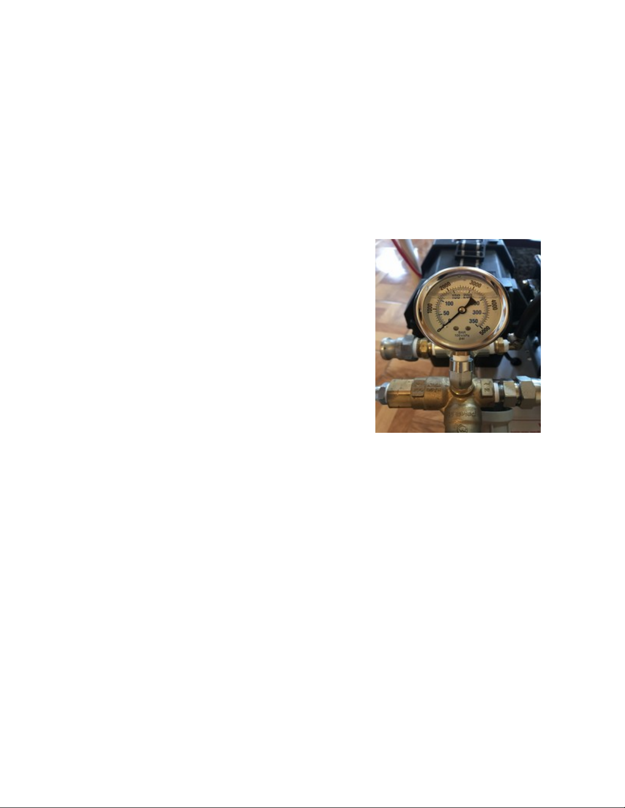
1. If using a calibration pressure gauge situated between the pressure hose and the CaviBlaster®
gun, the water pressure should be 2,500-psi with the gun submerged and the gun trigger in
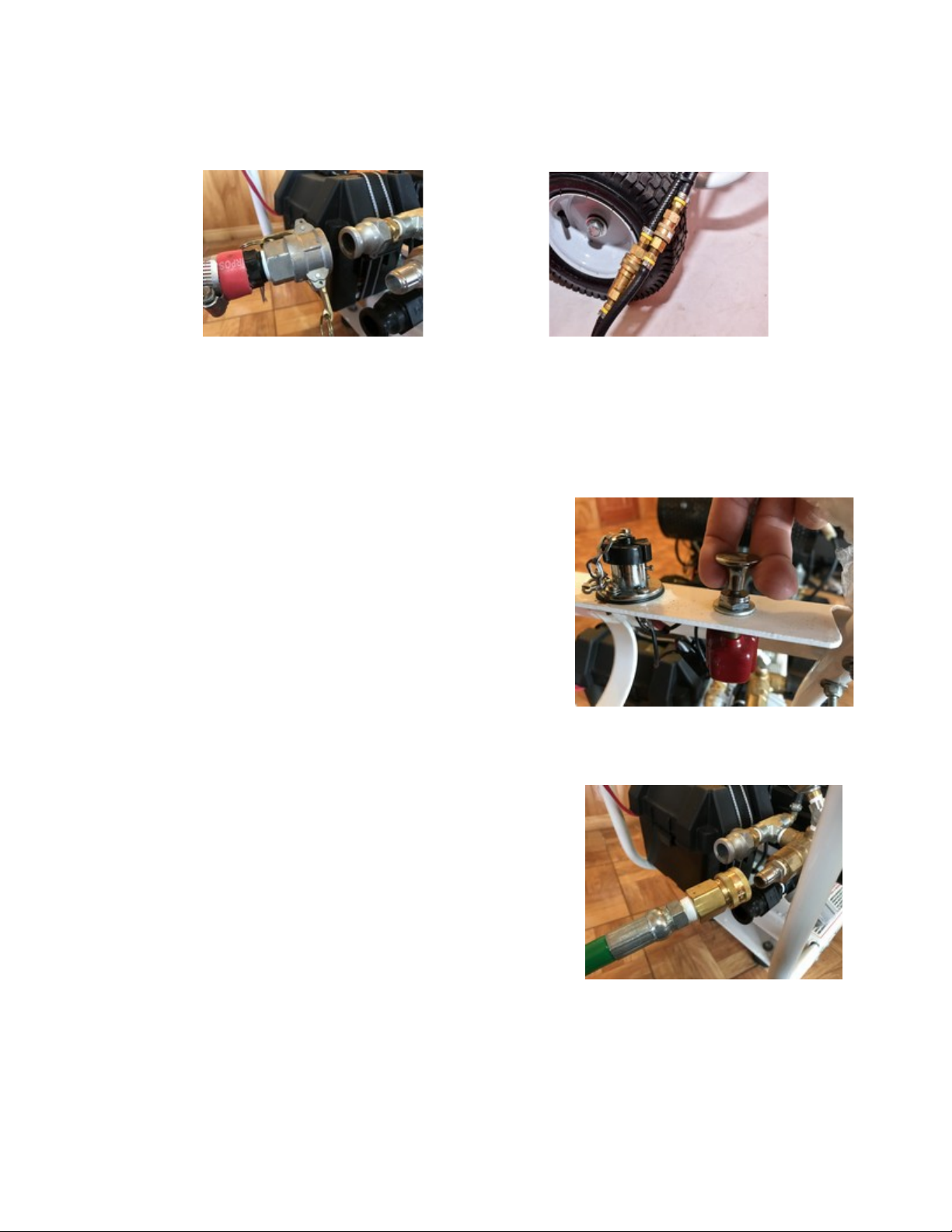
the open or “ON” position. The pressure is adjusted by turning the nuts on the end of the
pressure-regulating unloader (Figure 20). This adjustment increases or decreases the flow of
water through the bypass hose when the CaviBlaster® gun trigger is in the open or “on”
position. The flow of water through the bypass hose, in turn, determines the flow of water
through the pressure hose and the gun. Less flow through the bypass hose means more flow
through the gun which translates to higher velocity and pressure. There should always be a
trickle of water through the bypass when the gun trigger is in the open or “ON” position. This
ensures that the bypass will open without a pressure shock wave damaging the pump when
the gun trigger is released to the closed position.
2. If using a pressure gauge located on the
CaviBlaster® power unit, the water pressure
will need to be higher to account for sidewall
friction loss in the pressure hose. The pressure
at the pump should be 2,500-psi plus 0.75-psi
per foot of pressure hose. For example, if using
the CaviBlaster® with 100 feet of pressure
hose, the pressure gauge located next to the
pump should indicate 2,575-psi. Pressure
adjustments are made in the same manner as
described above. There should always be a
trickle of water through the bypass when the
gun trigger is in the open or “ON” position.
Figure 20
. If adjusting the CaviBlaster® without a pressure gauge, close the pressure-regulating unloader
until there is just a trickle of water (less than ¼ gallon per minute) coming out of the bypass
with the gun trigger in the open or “ON” position.
Page - 9
CaviBlaster 1325-G Operations Manual
For More information please email sales@cavidyne.com or call 1-(352)275-5319

Shu ing down he CaviBlas er® power uni :
1. Adjust engine RPM to “MIN” (Figure 18).
2. Shut off the engine by turning the key to the “OFF” position (Figure 16).
. Stop the feed pump by moving the feed pump switch to the “OFF” position (Figure 1 ).
4. Squeeze the gun trigger to the open or “ON” position (Figure 19) to release the water
pressure remaining in the hose(s) while he gun is submerged.
5. It is now safe to remove the gun from the water.
6. Flush the system and rinse the power unit with fresh water at the end of the day.
Main enance of he CaviBlas er® uni :
1. Empty and clean the inline strainer every day.
2. Check the oil level and consistency in the engine and pressure pump every day.
. Flush the system and rinse the power unit with fresh water after each days use,
for a leas 5 minu es, o make sure all inside residuals are removed.
4. Inspect the gear box oil level, and change it after the first month or 20 hours and every six months
or 100 hours thereafter.
5. Change the engine oil after the first month or 20 hours and every six months or 100
hours thereafter. Replace the oil filter every 200 hours. Use SAE 10W- 0 oil for general
all- temperature use.
6. Clean the air cleaner cover, filter elements and base every three months or 50 hours. Replace
the paper filter element every twelve months or 00 hours or if damaged or excessively dirty.
7. Change the oil in the pressure pump after the first 50 hours and every 500 hours thereafter.
Use single-weight lubricating oil (SAE 0 weight non-detergent)
8. Change the spring for the gun trigger every 12 months or less if required.
Page - 10
CaviBlaster 1325-G Operations Manual
For More information please email sales@cavidyne.com or call 1-(352)275-5319

Summarizing he opera ing ins ruc ions:
1. Inspect the system for damage. Clean the inlet strainer. Check oil/fuel
levels.
2. Attach all hoses to the unit and connect the feed pump electrical cable.
. Start the feed pump or alternate water supply and ensure that the system is
primed.
4. Attach the gun to the pressure hose.
5. Make sure that the diver is ready to work and that the gun is submerged in
the water.
6. Apply hearing protection, start the engine and adjust the throttle to
“MAX.”
7. Activate the cleaning cavitation stream by squeezing the gun trigger to
open or “on.”
8. Proceed with cleaning.
9. Stop the feed pump.
10. Release pressure from the hose(s) by squeezing the gun
trigger to the open or “ON” position while under wa er.
11. Remove the gun from the water.
12. Flush the system and rinse the outside of the power unit with fresh
water.
Page - 11
CaviBlaster 1325-G Operations Manual
For More information please email sales@cavidyne.com or call 1-(352)275-5319

WARNING
While the CaviBlaster® system is very safe, operators should exercise care when using the
equipment. The cavitation “flame” can be safely passed over the operators’ skin at normal
operating distances of 2” – ” from the tip of the nozzle. However, at very close distances
(typically less than 1”) both nozzles are capable of causing harm to the operator, particularly
in the initial instant that the system is activated. For that reason, opera ors should exercise
cau ion when opera ing he gun wi h he nozzles in close proximi y o he body. The
opera ors should also ensure ha he reverse- hrus nozzle guard is secured in he
correc posi ion prior o opera ing he gun.
The operators of the CaviBlaster® system should always wear neoprene or heavy rubber
gloves to provide protection to the hands and, in particular, to the nails. The gloves will
absorb most of the energy produced by bursting cavitation bubbles and prevent the cavitation
bubbles from contacting the operators’ hands. The gloves will also protect operators’ hands
from the initial shockwave when the gun is activated.
Serious harm and injury may resul from he misuse of CaviBlas er® sys em equipmen
or improperly selec ed fi ings, hoses or a achmen s. All components of the system
should be checked against the manufacturers’ instructions to ensure that they are compatible
with the pressures being used and of the correct thread type and pressure rating for the
intended service. Refer to these Operating Instructions and to the engine and pressure pump
manufacturers’ operation manuals for instructions or call CaviDyne, LLC at ( 52) 275-5 19
with any questions.
CAUTION: DO NOT USE IT TO CLEAN SENSITIVE
SURFACES as LED-Lights, Underwater Lights,
Ele troni Equipment, Et .
Page - 12
CaviBlaster 1325-G Operations Manual
For More information please email sales@cavidyne.com or call 1-(352)275-5319

Components
By-Pass Hose High Pressure Hose
Water Inlet Pump-Hose Zero Thrust Gun
High Pressure Lan e Gasoline Tank
Complete System
Page - 13
CaviBlaster 1325-G Operations Manual
For More information please email sales@cavidyne.com or call 1-(352)275-5319
Table of contents
Other Caviblaster Cleaning Equipment manuals
Popular Cleaning Equipment manuals by other brands

Alfalaval
Alfalaval Gunclean Toftejorg 270FT Mark 1 instruction manual

Good Way
Good Way GDS-C40 Operating and maintenance instructions

Vermes
Vermes NCS 11 user manual

Roller's
Roller's Metro 22 operating instructions

Elcometer
Elcometer Sagola Classic P1 instruction manual

Air Quality Engineering
Air Quality Engineering MistBuster 500 Installation and operation manual