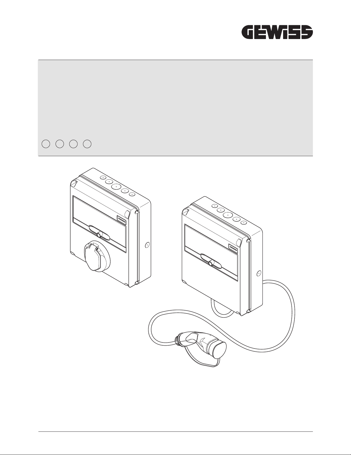
JOINON EASY electric vehicle recharging unit
26
This section describes the safety warnings and the personal protective equipment.
3.1. SAFETY CONDITIONS
General warnings
he operations described in this manual may only be performed by duly qualified personnel.
When this manual refers to qualified personnel, this means personnel complying with all the standards, directives and laws
concerning safety, as applicable to the installation and operation of this device.
he selection of qualified personnel is always the responsibility of the company that carries out the work, which is the only
party that can decide whether a worker is capable of doing a certain job, thereby ensuring their safety and respecting the
applicable law with regards safety in the workplace.
hese companies must provide suitable training regarding the electrical devices for their personnel, and make sure they
become familiar with the content of this manual.
It is mandatory to comply with the applicable safety laws relating to electrical work. here is the risk of possible electrical
shock.
Risk of electric shock.
Compliance with the safety instructions provided in this manual or by the legislation indicated does not imply exemption
from compliance with other specific standards regarding the installation, location, country or other circumstances that
concern the device.
he opening of the casing does not imply the absence of voltage inside.
Interventions must only be carried out once the voltage supply to the system has been cut o using a device that can
guarantee insulation.
It may only be opened by qualified personnel, following the instructions given in this manual.
It is mandatory to read and understand all parts of this manual before starting to handle, install or use the unit.
Gewiss declines all liability for any damage caused by inappropriate use of the charging stations. Any operation carried
out on these charging stations that involves a change to the original electrical settings must be authorised by Gewiss
beforehand. All such proposals must be examined and approved by Gewiss.
Before carrying out any interventions, cut o the voltage supply to the system using a device that can guarantee insulation.
As the minimum safety measure for this operation, observe the following rules:
1. Cut o the voltage supply.
2. Prevent the reactivation of the power supply.
3. Check that there is no voltage.
4. Protect yourself against energised elements nearby and place safety signals to mark o the work area if
necessary.
Until these steps have been applied, the product must be considered powered; no interventions are therefore authorised.
otential hazards for people
In order to protect your own safety, observe the following warnings.
HAZARD: crushing and injury of limbs.
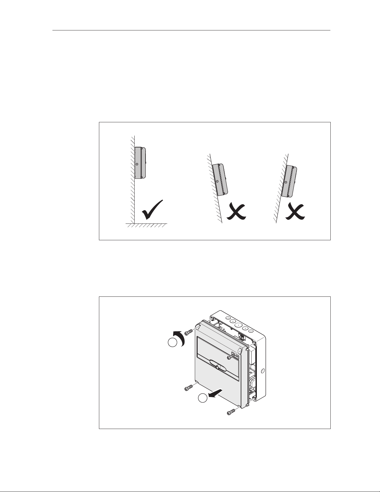
Always follow the instructions supplied in the manual for device handling and positioning.
he weight of the device can cause injuries if not handled correctly.
SAFETY
3.