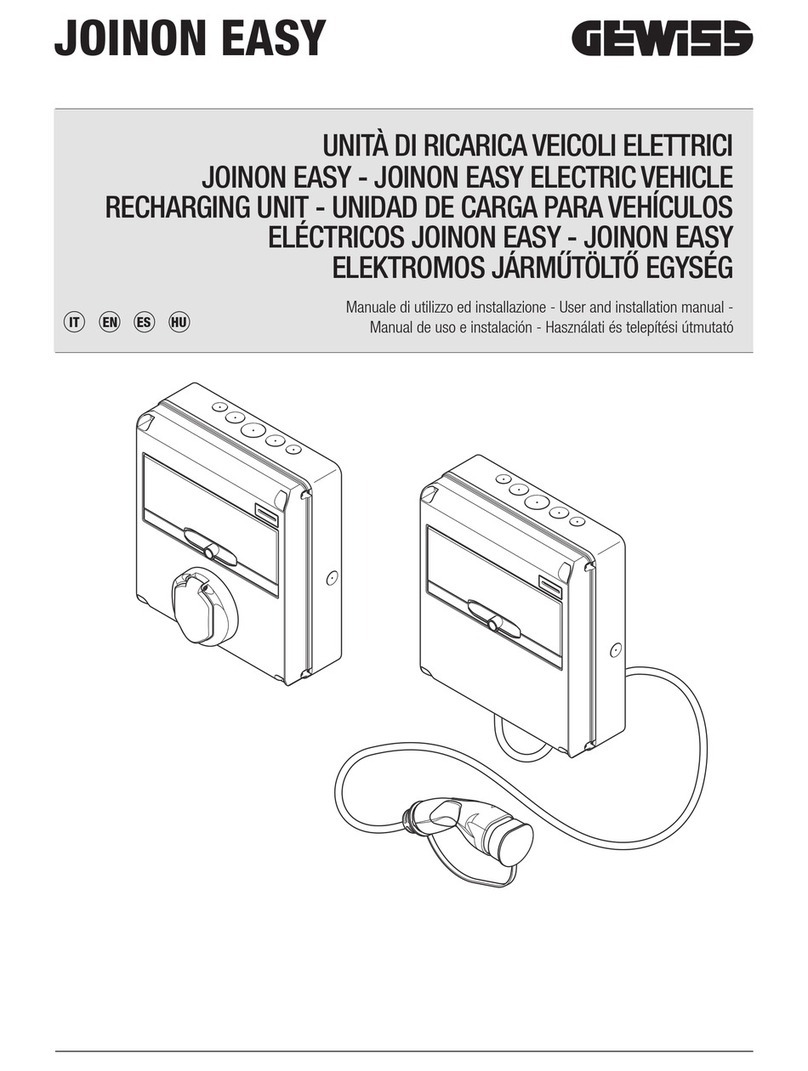
Gewiss JOINON I-CON Operating manual

JOINON EICHRECHT
I-CON AND I-ON
User and installation manual
JOINON ELECTRIC VEHICLE RECHARGING UNIT
EN

JOINON Electric vehicle recharging unit
2
CONTENTS
1. INFORMATION ABOUT THIS MANUAL 4
1.1 Field of application 4
1.2 Intended users 4
1.3 Symbols 4
2. DESCRIPTION OF THE DEVICE 5
2.1 Models 5
2.2 Description of the device 5
2.3. Fulfilment of regulations 8
2.4 Degree of protection 8
2.5 Degree of pollution 8
2.6 Current socket-outlets 9
3. SAFETY FUNCTION 10
3.1. Safety conditions 10
3.2. Personal protective equipment (PPE) 11
4. DEVICE DELIVERY AND STORAGE 12
4.1. Delivery 12
4.2. Device identification 12
4.3. Damage during transportation 12
4.4. Storage 12
5. DEVICE HANDLING 13
5.1. Transport 13
5.2. Packaging removal 13
6. PREPARATION FOR DEVICE INSTALLATION 14
6.1. Environment 14
6.2. Environmental conditions 14
6.3. Support and fixing surface (I-ON floor-mounting version) 14
7. INSTALLING AND CONNECTING THE DEVICE 16
7.1. General installation requisites 16
7.2. Device installation (I-ON floor-mounting version) 17
7.2.1. Mechanical installation 17
7.2.2. Connecting the device power supply 18
7.3. Device installation (I-ON surface-mounting version) 19
7.3.1. Mechanical installation 19
7.3.2. Connecting the device power supply 22
7.4. Device installation (I-CON basic surface-mounting version) 24
7.4.1. Opening the casing 24
7.4.2. Closing the casing 25
7.4.3. Opening the casing 26
7.4.4. Connecting the device power supply 29

3
8. CONFIGURATION OF THE CHARGING STATION
8.1. COMMISSIONING 31
8.2. Preliminary tests 31
8.2.1. Material needed to carry out the tests 31
8.2.2. Quality control 31
8.2.3. Operating tests 35
8.2.4 Retrieving the event logger 36
9. CHARGING STATION OPERATION 37
10 STATUS INDICATORS 37
10.1. RGB LEDs 37
10.2. Alphanumerical displays 37
11 ENERGY METER DISPLAY 38
11.1. Display of the energy meter info 38
11.2. Welcome screen of the energy meter 39
11.3. LCD display information of the energy meter 39
11.4 LCD Errors of the energy meter 44
12 CHARGING PROCESS 45
13 FAULTS AND TROUBLESHOOTING 45
14 DEVICE DIMENSIONS 48
14.1. I-ON COLUMN 48
14.2. I-ON WALLBOX 48
14.3. I-CON WALLBOX 49
15 REQUIREMENTS TO BE ADOPTED FOR USERS OF THE CHARGING DEVICES AND USERS OF THE
MEASURED VALUES 50
15.1. Requirements for users of the charging devices 50
15.2. Requirements for the user of the measurement values 51

JOINON Electric vehicle recharging unit
4
1.1. FIELD OF APPLICATION
This manual applies for the following charging stations:
I-ON JOINON – Column: OCPP cloud version
I-ON JOINON – Wallbox: OCPP cloud version
I-CON Basic JOINON – Wallbox: OCPP cloud version
1.2. INTENDED USERS
This document is intended for qualified personnel.
When this manual refers to qualified personnel, this means personnel complying with all the standards, directives
and laws concerning safety, as applicable to the installation and operation of this device.
The selection of the qualified personnel is always the responsibility of the company that performs the work, as it
is the sole party responsible for deciding if a worker is suitable for performing a certain job, thereby ensuring their
safety and respecting the applicable law on safety at work.
These companies must provide suitable training regarding the electrical devices for their personnel, and make
sure they become familiar with the content of this manual.
1.3. SYMBOLS
This manual uses various symbols to stress and highlight certain information.
Their general meaning is indicated below.
General caution
Electric risk
Prohibition
General information
Refer to the indicated section
INFORMATION ABOUT THIS MANUAL
1.

5
2.1. MODELS
I-ON JOINON – Column: OCPP cloud version
I-ON JOINON – Wallbox: OCPP cloud version
I-CON Basic JOINON – Wallbox: OCPP cloud version
2.2. DESCRIPTION OF THE DEVICE
I-ON COLUMN
Key:
DESCRIPTION OF THE DEVICE
2.
∗
Top
RGB LED socket-outlet status
Side instructions
Display
RFID reader
Type 2 charging socket-outlets
Lock with safety key*
Technical label
Base*
Electronic boards
Main switch*
Type B IDP*
MT*
MID energy counter
Contactor
Heater*
Router*
Windows for energy meters
* optional accessories

JOINON Electric vehicle recharging unit
6
I-ON WALLBOX
Key:
Top
RGB LED socket-outlet status
Side instructions
Display
RFID reader
Type 2 charging socket-outlets
Lock with safety key*
Technical label
Electronic boards
MID energy counter
Contactor
Router*
Windows for energy meters
* optional accessories

7
I-CON WALLBOX
Key:
Type 2 charging socket-outlets
RGB LED socket status
Window for energy meter
QRcode energy meter
Energy meter
Contactor
Electronic boards
DC leak
Supply terminal blocks

JOINON Electric vehicle recharging unit
8
2.3. FULFILMENT OF REGULATIONS
CE MARKING
CE marking is essential for marketing the products in question within the European Union and the European Eco-
nomic Area. The charging stations have CE marking as they comply with the following directives:
• Low Voltage Directive 2014/35/EU.
• Electromagnetic Compatibility directive 2014/30/EU.
• RED directive 2014/53/EU (version with RFID and/or GSM).
• ROHS directive 2011/65/UE + 2015/863
• Measuring Instruments Directive 2014/32/UE
• Mess- und Eichverordnung ( MessEV) and Mess- und Eichgesetzes (MessEG)
LOW VOLTAGE DIRECTIVE
The recharging stations comply with this directive as they fulfil the applicable parts of the harmonised standard EN
61851-1: Electric vehicle conductive charging system - Part 1: General requirements
EN IEC 61439-7:2020 Low-voltage switchgear and controlgear assemblies - Part 7: Assemblies for specific
applications such as marinas, camping sites, market squares, electric vehicle charging stations
ELECTROMAGNETIC COMPATIBILITY DIRECTIVE
The charging stations comply with this directive, as they fulfil the applicable parts of the harmonised standards:
• IEC 61851-21-2 Electric vehicle conductive charging system - Part 21-2: Electric vehicle requirements for
conductive connection to an AC/DC supply - EMC requirements for o board electric vehicle charging systems
RED DIRECTIVE
• ETSI EN 300 330 V2.1.1 (RFID)
Mess- und Eichverordnung ( MessEV) and Mess- und Eichgesetzes (MessEG)
• EN 50470-3:2006 Electricity metering equipment (a.c.) - Part 3: Particular requirements - Static meters for
active energy (class indexes A, B and C)
• VDE-AR-E 2418-3-100:2020-11
• WELMEC 7.2, 2020
• REA 6A
• PTB-A 50.7
2.4. DEGREE OF PROTECTION
These charging stations have an IP55 degree of protection against external agents.
This device is designed for indoor and outdoor use (column and WallBox version).
2.5. DEGREE OF POLLUTION
The5pollution degree that these stations are designed for is level 3 with reference to Standard IEC 60664-1.

9
2.6. CURRENT SOCKET-OUTLETS
The charging stations can be supplied with various connector configurations, depending on the customer's require-
ments.
The following connectors are available:
IEC 62196-2 Type 2 - cable + mobile connector
IEC 62196-2 Type2
Depending on the model, the column version of JOINON charging stations may have two socket-outlets that can be
used simultaneously.

JOINON Electric vehicle recharging unit
10
This section describes the safety warnings and the personal protective equipment.
3.1. SAFETY CONDITIONS
General warnings
Potential hazards for people
In order to protect your own safety, observe the following warnings.
SAFETY FUNCTION
3.
The operations described in this manual may only be performed by duly qualified personnel.
When this manual refers to qualified personnel, this means personnel complying with all the standards, directives and laws
concerning safety, as applicable to the installation and operation of this device.
The selection of qualified personnel is always the responsibility of the company that carries out the work, which is the only
party that can decide whether a worker is capable of doing a certain job, thereby ensuring their safety and respecting the
applicable law with regards safety in the workplace.
These companies must provide suitable training regarding the electrical devices for their personnel, and make sure they
become familiar with the content of this manual.
It is mandatory to comply with the applicable safety laws relating to electrical work. There is the risk of possible electrical
shock.
Risk of electric shock.
Compliance with the safety instructions provided in this manual or by the legislation indicated does not imply exemption
from compliance with other specific standards regarding the installation, location, country or other circumstances that
concern the device.
The opening of the casing does not imply the absence of voltage inside.
Interventions must only be carried out once the voltage supply to the system has been cut o using a device that can
guarantee insulation.
It may only be opened by qualified personnel, following the instructions given in this manual.
It is mandatory to read and understand all parts of this manual before starting to handle, install or use the unit.
Gewiss disclaims all liability for any damage caused by inappropriate use of the charging stations. Any operation carried
out on these charging stations that involves a change to the original electrical settings must be authorised by Gewiss
beforehand. All such proposals must be examined and approved by Gewiss.
Before carrying out any interventions, cut o the voltage supply to the system using a device that can guarantee insulation.
As the minimum safety measure for this operation, observe the following rules:
1. Cut o the voltage supply.
2. Prevent the reactivation of the power supply.
3. Check there is no voltage.
4. Protect yourself against energised elements nearby, and place safety signals to mark o the work area if
necessary.
Until these steps have been applied, the product must be considered powered; no interventions are therefore authorised.
HAZARD: crushing and injury of limbs.
Always follow the instructions supplied in the manual for device handling and positioning.
The weight of the device can cause injuries if not handled correctly.

11
Potential hazards for the device
In order to protect the device, observe the following warnings.
3.2. PERSONAL PROTECTIVE EQUIPMENT (PPE)
When working on the device, use at least the following items of safety equipment.
Name Explanation
Safety footwear In accordance with UNE-EN-ISO 20345:2012 or the latest edition published
Helmet In accordance with EN 397:1995 or the latest edition published
Helmet with a face mask In accordance with UNE-EN 166:2002 or the latest edition published, if there are live elements
that can be directly accessed.
Work garments Close-fitting and non-flammable, in 100% cotton
Dielectric gloves In accordance with EN 60903:2005 or the latest edition published
The equipment or devices used for operations with the system energised must have at least category III-1000 Volt insulation.
If the regulations in the location of installation require other types of personal protective equipment, the equipment must be
integrated in a suitable manner.
During operation, the device requires an air flow free of impurities.
It is vital to maintain the vertical position and keep the entrances free of obstacles, to allow the air flow to enter inside the
device.
Before reconnecting the voltage supply after any duly authorised operation, make sure the device is ready to start working.
Then, connect it following the instructions in the manual.
Do not touch the boards or the electronic components; the more sensitive components may get damaged or be destroyed
by static electricity.
Do not disconnect or connect any terminal while the device is operating. Disconnect and check for the absence of voltage
before performing any operation.

JOINON Electric vehicle recharging unit
12
4.1. DELIVERY
Keep the device packaged until installation.
4.2. DEVICE IDENTIFICATION
The serial number of the device identifies it in an unequivocal manner.
The device serial number is also shown on the technical data plate on the lower part of the front panel.
4.3. DAMAGE DURING TRANSPORTATION
The serial number of the device identifies it in an unequivocal manner. In any communication with Gewiss, refer-
ence must be made to this number.
The device serial number is indicated with a data matrix on the technical data label (on the side of the front panel).
If the device was damaged during transport:
• Do not install it.
• Notify your reseller of the damage within 5 days of receiving the device.
If it is necessary to return the device to the manufacturer, the original packaging must be used.
4.4. STORAGE
Failure to observe the instructions provided in this section could cause damage to the device.
If the device is not installed immediately upon delivery, to avoid its deterioration, proceed as indicated below:
• To ensure the charging station is correctly conserved, do not remove the original packaging until it is ready to
be installed.
• Deterioration of the packaging (cuts, holes, etc.) prevents the correct conservation of the charging stations prior
to installation.
• Keep the device clean (remove dust, wood shavings, grease, etc.), and keep rodents away from it.
• Protect it from water spray, welding sparks, etc.
• Cover the device with a protective breathable material to avoid condensation caused by environmental humidity.
• Charging stations kept in a warehouse must not be subjected to climatic conditions other than those indicated
below:
Ambient storage conditions
Minimum storage temperature -40°C
Maximum storage temperature 70°C
Maximum relative humidity without condensation 95%
• It is very important to protect the system against corrosive chemical products and saline environments.
• Do not store the device where it is exposed to bad weather conditions.
DEVICE DELIVERY AND STORAGE
4.

13
DEVICE HANDLING
5. During transportation, the device must be protected against mechanical shocks, vibrations, water spray (rain) and
any other product or situation that might damage it or alter its operation.
When moving the devices, keep them horizontal.
N
Do not move the devices by pressing on the recharging socket-outlets.
5.1. TRANSPORT
HANDLING WITH A PALLET TRUCK
At least the following provisions must be observed:
• Set the stations down (still packaged) in a central position in relation to the forks.
• Position them as close as possible to the point where the forks are joined to the upright.
• In any case, respect the instructions given in the pallet truck user manual.
HANDLING WITH A FORKLIFT
At least the following provisions must be observed:
• Set the stations down (still packaged) in a central position in relation to the forks.
• Position them as close as possible to the point where the forks are joined to the upright.
• Make sure the forks are perfectly levelled, to avoid any risk of the device tipping over.
• In any case, respect the instructions given in the forklift user manual.
Only unpack the charging station when you are ready to install it and have brought it to the place of installation. At
this point, it can be transported vertically and without its packaging, but only for a short distance.
HANDLING THE UNPACKAGED DEVICE
At least the following provisions must be observed:
• Follow the fundamental ergonomic recommendations to avoid injuries when lifting weights.
• Do not release the device until it is firmly fastened or supported.
• Follow the indications of another person who is guiding the movements.
5.2. PACKAGING REMOVAL
• The correct handling of the charging stations is very important to:
• Avoid damaging the packaging that maintains their optimum condition, from shipment to the moment they are
installed.
• Avoiding knocking or dropping the charging stations as this could jeopardise their mechanical properties.
• Avoid, as far as possible, the vibrations that could cause subsequent abnormal operation.
To allow the installer to prepare the column fixing area beforehand, the base is inserted in the packaging in such
a way that it can be taken out separately from the charging unit.
The base can therefore be removed from the packaging and installed on the ground, attached to the tie-rods
embedded in the cement or to the anchor plugs already fitted in the ground (as shown below):
DISPOSING OF THE PACKAGING
The packaging is 100% cardboard, and can be taken to an authorised sorted waste collection point.

JOINON Electric vehicle recharging unit
14
• It is prohibited to leave any object on the device.
• In the case of connected devices, avoid positioning them near metal fences or walls which could cause signal
disturbance problems.
6.2. ENVIRONMENTAL CONDITIONS
The following table shows the device operating conditions in the standard configurations and with the accessories
(fan and heater):
Environmental conditions Column and WallBox
Minimum storage temperature -25°C
Maximum storage temperature 50°C
Maximum relative humidity without condensation 95%
Remember that it could occasionally produce a small amount of condensation as a result of temperature changes.
Therefore, in addition to the protection it has, the charging stations must be monitored when they are used in
areas where it is probable that not all the previously indicated conditions will be satisfied.
Never connect the device to the voltage supply when there is condensation.
NB= If the ambient temperature is higher than 40°C, a cover must be installed to protect the device from
direct sunlight.
6.3. SUPPORT AND FIXING SURFACE (I-ON FLOOR-MOUNTING VERSION)
Ensure there is a firm, even surface for anchoring the device, which must be perfectly vertical.
The installation surface must be suitably prepared according to the type of ground, to guarantee that the device is
stable during use. You are therefore advised to use the base supplied (column version), fixing it to the ground by
means of tie-rods (not supplied) or plugs, or embedded in cement.
When deciding the location of the device and preparing for its installation, a series of instructions linked to its
properties must be followed.
6.1. ENVIRONMENT
• Position the charging station in a location that can be accessed for installation and maintenance, which permits
its use and the reading of the LED indicators.
• Do not position any material sensitive to high temperatures in the immediate vicinity of its air outlet.
• Avoid corrosive environments that could have an influence on the correct operation of the device.
PREPARATION FOR DEVICE INSTALLATION
6.

15
Install the charging station in the prepared area, maintaining the necessary distance between it and the surround-
ing area (as shown in the figure).
BACK
FRONT
50 cm50 cm
5 cm
30 cm
The charging column can be installed in back-to-back configuration with another column, to make the best use
of the space available. This particular configuration requires only one power supply line and a single plinth for the
installation of two devices, as shown below:
FRONT
FRONT
2 cm
There must be a minimum distance of 2cm between the back panels of the two charging units.
NB= The surface on which the charging station is to be installed must be designed and built in accord-
ance with the standards and the regulations in force, to ensure the safety of users regardless of the type
of surface.
BACK
FRONT
FRONT
FRONT

JOINON Electric vehicle recharging unit
16
Before proceeding with device installation, remove the packaging, paying particular attention to not damage the
casing.
Make sure there is no condensation inside the packaging. Otherwise, install the device only when it is completely
dry.
All the installation operations must be carried out in compliance with the directive in force.
All operations that involve moving large weights must be done by two people.
The connection must only be made by qualified personnel, when the system is disconnected from the
power supply.
Scrupulously check that the device is not energised when accessing it inside.
To measure the lack of voltage, use dielectric gloves and safety goggles that are type-approved for
electrical risks.
All the installation operations must be carried out respecting the safety regulations and laws in force,
and following the instruction manual
7.1. GENERAL INSTALLATION REQUISITES
• The device must be installed in a suitable environment that satisfies the information described in chapter “6.
Preparation for device installation”. Furthermore, the elements used in the rest of the installation must be com-
patible with the device and compliant with the applicable law.
• The ventilation and work space must be suitable for the maintenance operations according to the directive in
force.
• The external connection devices must be suitable and observe the distance established by the directive in force.
• The section of the connection cables must be suitable for the maximum current intensity set on the charging
unit.
• Keep external elements away from the air intakes and outlets, as these could prevent correct device ventilation.
INSTALLING AND CONNECTING THE DEVICE
7.

17
7.2. DEVICE INSTALLATION (I-ON FLOOR-MOUNTING VERSION)
7.2.1. MECHANICAL INSTALLATION
• Prepare the assembly area with four tie-rods embedded in the cement (if you are using the fixing plate - acces-
sory GWJ8021 - embed it in the ground). The figure below shows the position of the anchorage point on the
device. There are two options for fixing the device in the ground:
150 mm
150 mm
100 mm
196 mm
Ø14 mm
Ø14 mm
NB= The fixing points highlighted in blue allow this device to be installed in place of the old Parking+
devices.
• These charging stations have a front access door with key opening to facilitate installation and connections.
Open the door using the key supplied. The safety key can only be removed when the door is fully closed.
• Couple the fixing base (already fixed to the ground) with the charging station.
• Fix the column on the base, tightening the nuts on the pins indicated in the figure. The maximum tightening
torque is 20 Nm.
NB= It's important to complete the earth connection of the base. To do this, insert the eyelet of the
earth cable on a fixing pin, then tighten it with the relative nut as shown in the figure.
• Check the device is properly fixed.
• Remove the protective film from the front panel.

JOINON Electric vehicle recharging unit
18
7.2.2. CONNECTING THE DEVICE POWER SUPPLY
WIRING REQUISITES
The connection must satisfy certain requisites:
CONNECTION SPECIFICATIONS
Type of connection Three-phase
Number of wires 3P+N+E
Rated current Up to 64A
Maximum wire diameter 1 x 70mm2 (2 x 35mm²)
NB= The in-out connection can be made for a maximum of 2 columns connected in series.
CONNECTION PROCEDURE
• The charging station is wired by connecting a single-phase or three-phase cable inserted in the cable gland.
The appropriate cable glands are M50, M40, M32 for the power cables (highlighted in yellow), and M16 for the
data cables (highlighted in red).
Depending on the charging unit version, the cable glands and caps supplied are as follows:
VERSION CABLE GLANDS SUPPLIED CAPS SUPPLIED
Three-phase 2x 22 kW M40 M32, M50
• Connect the power supply cables L, N, PE.
PE
TN
RS
R, S, T: R, S, T phases
N: Neutral
PE: Earth

19
• Switch ON the residual current protection and circuit breaker protection, and power the column.
• Check the residual current protection is working properly, by pressing the relative test button key.
LINE REQUISITES
As the charging stations are equipped with type B residual current protection, or type A [EV] in the version with
Restart (as shown in the electrical diagram attached), if a residual current circuit breaker needs to be installed
upstream of the power supply line, it must be of the same type.
NOTE REGARDING THE INTERNAL WIRING
To obtain a better balance in the case of single-phase recharges, which can be made simultaneously on both
connectors, the internal wiring of the phases has been inverted on the two socket-outlets.
The internal wiring sequence is as follows:
7.3. DEVICE INSTALLATION (I-ON SURFACE-MOUNTING VERSION)
7.3.1. MECHANICAL INSTALLATION
If the product is to be installed on the wall (using the accessory supplied), the procedure is as follows:
MINIATURE CIRCUIT
BREAKER
1
MINIATURE CIRCUIT
BREAKER
2
RCCB
1
RCCB
2
SWITCH
DISCONNECTOR

JOINON Electric vehicle recharging unit
20
• Prepare the assembly area by fixing the support bracket to the wall, drilling holes with the centre distances
shown below:
189,5 mm
513 mm
94,75 mm 94,75 mm
Ø6,5 mm
Ø6,5 mm
• Assemble the brackets (supplied) on the back panel of the WallBox:
2,5 Nm
Other manuals for JOINON I-CON
2
This manual suits for next models
1
Table of contents
Other Gewiss Batteries Charger manuals

Gewiss
Gewiss JOINON User manual

Gewiss
Gewiss I-CON BASIC Operating manual

Gewiss
Gewiss JOINON WALLBOX I-CON DLM User manual

Gewiss
Gewiss GW68122 Operating manual

Gewiss
Gewiss GWJ3001A Operating manual

Gewiss
Gewiss JOINON I-CON PREMIUM GWJ3201A Operating manual

Gewiss
Gewiss JOINON EASY Series Operating manual
Popular Batteries Charger manuals by other brands

Fillauer
Fillauer Motion Control Internal Li-Ion Battery Set user guide

Lenmar
Lenmar Lenmar PRO9V2 instruction manual

Tronic
Tronic TLG 1000 C4 operating instructions

Weinmann
Weinmann FW7405M/14 Description and operating instructions

EVBox
EVBox Troniq installation manual

DSE
DSE DSE9462 installation instructions