GFA TS 971 Series Product guide
IMPORTANT
In accordance with EN12453 self-checking or self-testing safety edge or a device
certified as type ‘E’ according to EN12453 i.e. light curtain fitted directly in line
with the moving leaf of the door must be fitted to doors that close by impulse
remote or automatic activation.
In addition doors operated by untrained users in public areas activated by
impulse out of sight of the door or automatic control must be fitted with a photo
beam or photo beams to detect persons or obstacles standing on the floor to one
side of the door.
The photo beams do not need to be self-checking or self-testing but they should
be subject to periodic checks at intervals not exceeding six months.
Grilles and doors that have hand or foot holds that can be used to ride on the
door must be fitted with devices to protect against trapping i.e. Raytector
Entrapment Protection Barrier that when obstructed stops all movement of the
door.
Note
A Maintenance Cycle Counter is included in the TS 971. (See Control
Progra ing 8.5 and 8.6)
When co issioning the Shutter set the Counter according to the Shutter
Manufacturers reco endations.
08.2018
TS 971-
Industrial
Door Control
Connection Drawings
INSTRUCTIONS
The anufacturer’s instruction
booklet supplied with the TS 971
contains i portant directions
and warnings for the safe use of
this equip ent and should be
read before installation or
co issioning is undertaken.

TS 971 Industrial Door Control
2
Contents
TS 971 - Connection of the drive unit to the Control Panel 4
TS 971 - Main Supply – 3 Phase for 3 Phase Door Drives 5
TS 971 - Main Supply – 1 Phase for 1 Phase Door Drives 6
Safety Brake – Drive Connection 7
TS 971 - KSR4P – Optical Safety Edge 8
TS 971 - KSR6 – Wireless Optical Safety Edge 9
TS 971 – GF304528 Raytector High Level Entrapment Protection Barrier 10
TS 971 – ELC1930/OSE ELC2290/OSE ELC2650/OSE Light Curtain. 11
TS 971 – GF/RAY-LG2520/OSE GF/RAY-LG2524/OSE Light Curtain. 12
TS 971 – 2 x GF/RAY Light Curtains 13
TS 971 – Connecting an additional ‘OPEN / CLOSE’ Key Switch. 14
TS 971 - GE3 or GE3AN – Connecting an additional 3 Push Button Station. 15
TS 971 – Connecting an additional Key Switch with Stop Button. 16
TS 971 - PES/9R– Connecting a Reflective Photo Beam. 17
TS 971 - PES/30T– Connecting a Thru Beam Photo Beam. 18
TS 971 - Built-in Radio Receiver - memorising Radio Transmitters 19
TS 971 – Loop Detector PCB and Ground Loop 20
TS 971 – Latching Stop Button 21
TS 971 - IFALCONXL and IFALCON – Industrial Motion Sensor 22
TS 971 - ICONDORXL and ICONDOR – Industrial Motion & Presence Sensor 23
TS 971 - Power Supply for Control Accessories 24
TS 971 - 230VAC Warning Light 25
TS 971 - GE301955 - Red & Green Traffic Indicator 26
TS 971 – Interlocking 2 x TS971s Together 27

TS 971 Industrial Door Control
3
TS 971 - General Layout of Drive and Controls
SAFETY EDGE KIT KSR4P
PHOTO BEAM PES/9R OR PES/30T
DOOR CENTRE LINE
GE3A /
GE3AN
3 PUSH
BUTTON
STATION
SAFETY BRAKE (IF FITTED)
WIRELESS SAFETY EDGE KIT KSR6
I pulse
activation by
trained users
in full view of
the door.
Untrained
users,
activated by
i pulse out
of sight of
the door in
public areas
or auto atic
control

TS 971 Industrial Door Control
4
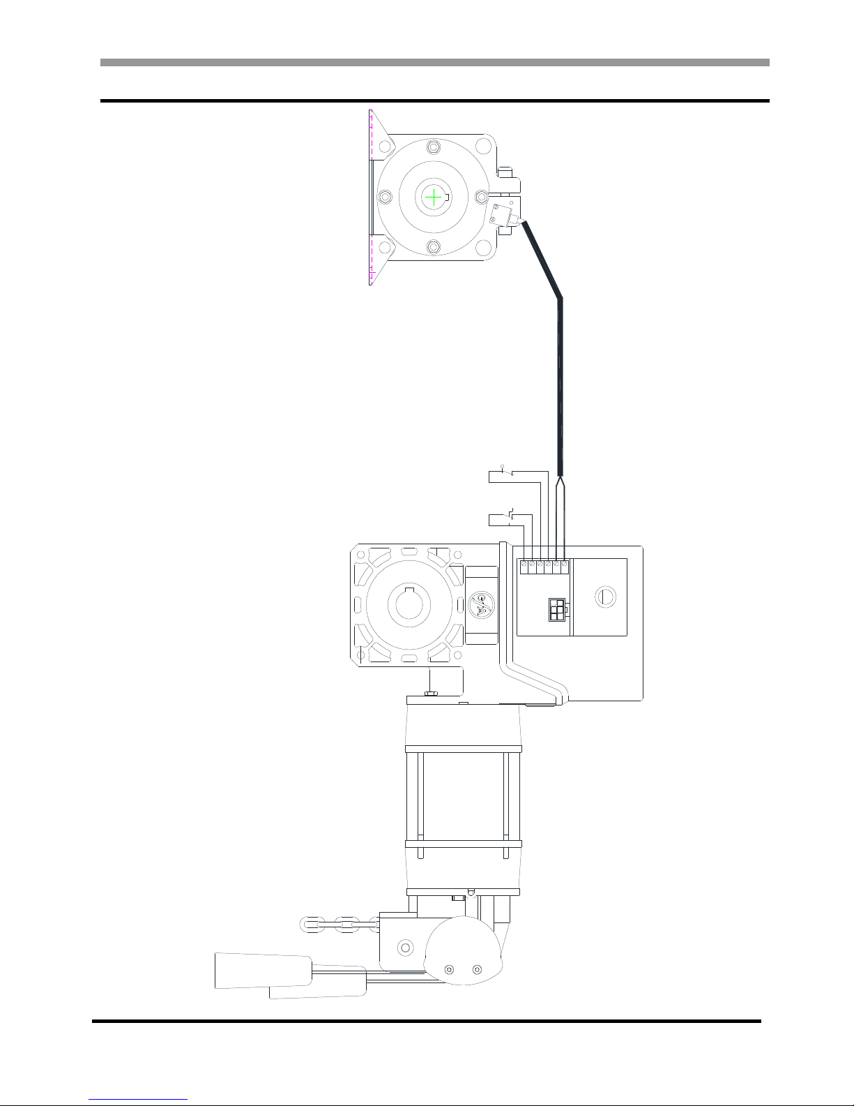
TS 971 - Connection of the drive unit to the Control Panel
The Motor / Limit protected cable is available in 3m 5m 7m 9m 13m and custom lengths up to
25m. The Motor / Limit cable must not exceed 25m.
Fig 2
F1 ,6A t
1.11.21.31.4
PIN Wire-No. Description
1 3 Phase W
2 2 Phase V
3 1 Phase U
4 4 Neutral
5PE Earth
PIN Wire-No. Description
1 5 Safety Chain 24V DC
26 RS485 B
3 7 GND
4 8 RS485 A
5 9 Safety Chain
6 10 8V DC
DIGITAL
LIMIT ASSEMBLY
26
25
24
23
22
21
PE
N
W
V
U
[4]
[3]
[E]
[2]
[1]
PE
N
W
V
U
MOTOR PLUG

TS 971 Industrial Door Control
5
TS 971 - Main Supply – 3 Phase for 3 Phase Door Drives
Fig 3a
The neutral is only required for FI drives or if 1~ 230VAC control accessories or indicator lamps are installed.
F1 = 1 6A t
1.11.21.31.4
L1L2L3 N E
L1 – Black
L2 – Brown
L3 – Grey
N – Blue
E – Green/Yellow

TS 971 Industrial Door Control
6
TS 971 - Main Supply – 1 Phase for 1 Phase Door Drives
There are two types of single-phase motors symmetric and asymmetric windings. To determine
how to connect the supply look at the motor connecting plug in the motor limit housing.
SYMMETRIC WINDING ASYMMETRIC WINDING
(Ranger Safedrive Mini and FI Drives) (Safedrive)
Fig 3b
UZ2
Z1
PE
U1
V
N
W
PE
U
C1
M
1 ~
Z1UZ2U1PE
Z2
U
V
PE
W
U1
Z1
PE
N U2
PE
1 ~
U1Z2 Z1
C1
M
NB.
NO CONNECTION
U2
NB.
CONNECTION
F1 = 1 6A t
1.11.2 1.3 1.4
L1 N E
F1 = 1 6A t
1.11.21.31.4
L1 N E
TS 971 Industrial Door Control
7
Safety Brake – Drive Connection
21
22
23
24
25
26
2
12
11
S10
1
MOTOR
THERMAL
EMERGENCY
OPERATOR
SAFETY BRAKE
INTERLOCK
GN/W (N/C)
SAFETY BRAKE
REMOVE LINK TO
CONNECT SAFETY BRAKE
10 9 8
765
DIGITAL LIMIT

TS 971 Industrial Door Control
8
TS 971 - KSR4P – Optical Safety Edge
Fig 4a
4 WH
3 GRN
2 YEL
1 BRN
SK/w
SK/g
SK/b
ST+
ST
2 x WHITE
2 x GREEN
2 x BROWN
1 BROWN
3 GREEN 2 YELLOW
4 WHITE
2.1
2.2
2.3
2.4
2.5
SHUTTER CENTRE LINE
SHOOT BOLT,
PASS DOOR OR
SLACK WIRE SWITCH
REMOVE LINK IF
CONNECTING SHOOT
BOLT, PASS DOOR OR
SLACK WIRE SWITCH
RECEIVEREMITTER
2.5
2.4
2.3
2.2
2.1
F1 1,6A t
TS 971 Industrial Door Control
9
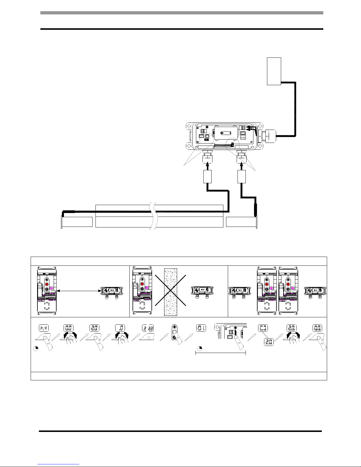
TS 971 - KSR6 – Wireless Optical Safety Edge
N.B. The TS 971 terminals 2.1 – 2.5 are disabled when the wireless safety edge used.
DO NOT CONNECT ANY DEVICE TO TS 971 TERMINALS 2.1 – 2.5
RECEIVEREMITTER
ST3 ST1
SET SWITCH
TO
POSITION'A'
ST3
ST2 ST1
P1
S1
B A IR
KL1
X1
X2
SHOOT BOLT,
PASS DOOR OR
SLACK WIRE SWITCH
REMOVE LINK FROM X1 IF CONNECTING SHOOT
BOLT, PASS DOOR OR SLACK WIRE SWITCH
N.B. IF NO SWITCHES ARE CONNECTED TO X1
REMOVE THE LINK AND REPLACE WITH THE 8K2
RESISTOR SUPPLIED WITH THE BATTERY
SET SWITCH
TO
POSITION'IR'
INSTALLATION AND PAIRING THE TS971 AND WIRELESS SAFETY EDGE
ST3
ST2 ST1
P1
S1
B A IR
KL1
X1
X2
10m
MAX
ST3
ST2 ST1
P1
S1
B A IR
KL1
X1
X2
OBSTRUCTIONS,
PARTICULARLY STEEL
OR REINFORCED
CONCRETE WILL REDUCE
THE RANGE OR BLOCK
THE SIGNAL ENTIRELY
ST3
ST2 ST1
P1
S1
B A IR
KL1
X1
X2
ST3
ST2 ST1
P1
S1
B A IR
KL1
X1
X2
SYSTEMS IN
THE SAME
AREA MUST BE
PROGRAMMED
TO DIFFERENT
CHANNELS.
3s
-
+
PRESS AND
HOLD FOR 3
SEC
TURN TO 2.0 PRESS ONCE
AND RELEASE
-
+
TURN TO SELECT
A CHANNEL.
-
PRESS STOP
ONCE AND
RELEASE
P1
X2
10s
WITHIN 10 SEC PRESS
WIRELESS SAFETY EDGE
BUTTON P1
*
*
-
+
*
THE ADDITIONAL DECIMAL
POINT INDICATES THAT
PAIRING IS SUCCESSFUL
*
TURN BACK TO 0.0
AND BREIFLY PRESS
TO EXIT
CONSULT THE TS971 INSTALLATION INSTRUCTIONS FOR FULL INSTRUCTIONS AND SAFETY INFORMATION
2 - 2.2
TS 971 Industrial Door Control
10
TS 971
–
GF304528
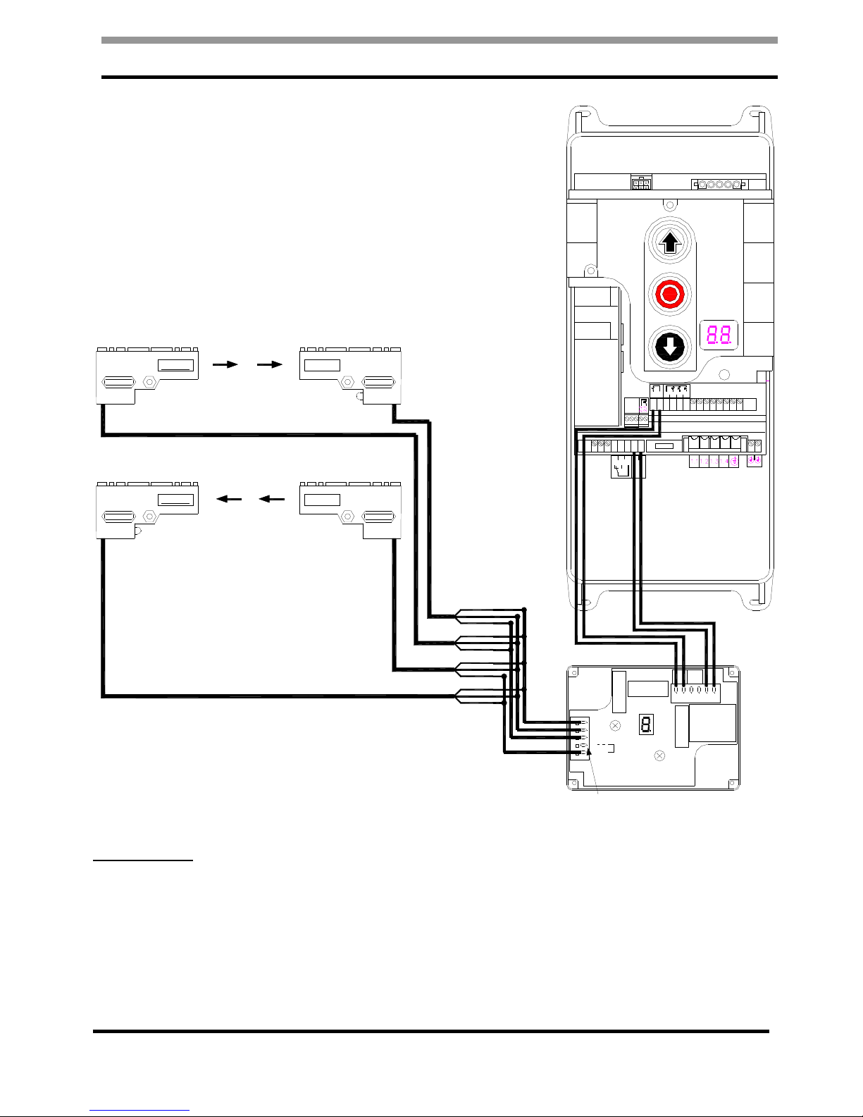
RAYTECTOR HIGH LEVEL ENTRAPMENT PROTECTION BARRIER
IMPORTANT!
READ THE RAYTECTOR INSTRUCTIONS FOR ESSENTIAL INSTALLATION AND TESTING
PROCEDURES.
5.1
5.2
5.3
5.4
3.1
3.2
20.3
20.2
20.1
1.8
1.9
F1 = 1 6A t
1 BN
2 WE
4 GN1
5
6 GN2
OSE-C 2300
2 x OSE
1 x OSE
RELAY 2
RELAY 1
RELAY 3
TRANSFORMER
34 33
OSE
24 23
REV
A1 A2
Power
VITECTOR RAYTECTOR
RAY - R 1000
Receiver
RAY - T 1000
Transmitter
light barrier
inside
VITECTOR RAYTECTOR
RAY - T 1000
Transmitter
RAY - R 1000
Receiver
light barrier
outside
BROWN
WHITE
GREEN
BROWN
WHITE
GREEN
BROWN
WHITE
GREEN
BROWN
WHITE
GREEN
4 x BROWN
4 x WHITE
2 x GREEN
2 x GREEN
REMOVE LINK
TERMINALS 5 - 6
RAYTECTOR HIGH LEVEL ENTRAPMENT
PROTECTION BARRIERS
Other manuals for TS 971 Series
2
Table of contents
Other GFA Controllers manuals


Popular Controllers manuals by other brands

Digiplex
Digiplex DGP-848 Programming guide

YASKAWA
YASKAWA SGM series user manual

Sinope
Sinope Calypso RM3500ZB installation guide

Isimet
Isimet DLA Series Style 2 Installation, Operations, Start-up and Maintenance Instructions

LSIS
LSIS sv-ip5a user manual

Rockwell Automation
Rockwell Automation 1769-L31 installation instructions


