manuals.online logo
Brands
  1. Home
  2. •
  3. Brands
  4. •
  5. Giacomini
  6. •
  7. Controllers
  8. •
  9. Giacomini Giacoklima Series Guide

Giacomini Giacoklima Series Guide

ActuAtor with integrAted regulAtor, K282
for r298 And r298n mixing vAlve
0262EN May 2013 047U31758
1
ISO
9001
0006/7
ISO
14001
0032A/2
OHSAS
18001
0064L/0
Description
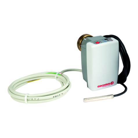
K282 actuator is an actuator that works both as motor and regulator, to
control the delivery temperature with three way mixing valve.
Thus, K282 actuator can be used on three way valves:
• it controls xed delivery temperature both heating and cooling, in“stand-
alone” functioning;
• it can carry out the regulation with climatic compensation when heating
and the xed regulation with calibration on internal thermohygrometric
conditions when cooling, in combination with KM203 network controller,
K365P external sensor, K481 or K483 thermostats and K485 ambient sensor.
Versions and product codes
Technical data
Main features
• M28x1,5 brass ring xing to valve body.
• Immersion probe for delivery water temperature with bulb, length 47 mm
and diameter 6 mm, connected to the actuator body.
• Proportional-integral (PI) digital electronic regulator inserted in the actuator
body.
• Motorized manual control (open ring) of the valve by selecting the opening
position (from 0% to 100%).
• Stand-alone functioning: manual selection by summer/winter mode
selector.
• Stand-alone functioning: manual selection of the working set by rotating
potentiometer with double adjustment scale. Winter mode from 20 °C to 60
°C; summer mode from 15 °C to 25 °C.
• Bus signal network functioning with KM203 network controller: climatic
compensation regulation during winter and calibration on internal
thermohygrometric conditions during summer.
Control elements
The summer/winter mode selector and the rotating potentiometer with
double adjustment scale to select the xed set for the delivery temperature
control are on the frontal side of K282 actuator.
Once summer/winter switching has been made through selector, position
the rotating potentiometer at the desired set according to the appropriate
graduated scale: the scale working during the winter is indicated with red
numbers (range from 20 °C to 60 °C ascending clockwise); the scale working
during the summer is indicated with blue numbers (range from 15 °C to 25 °C
ascending anticlockwise).
Both controls are used in stand-alone functioning of the actuator.
When K282 is used in combination with KM203 network controller, both
manual mode selector and rotating potentiometer are deactivated and their
use has no eect. In this application, the modication of delivery temperature
set or summer/winter switching is made by KD300 display.
K282
winter
20°C
25°C
20°C
40°C
60°C
15°C
summer
2
1
3
1 SUMMER/WINTER mode selector
2 RED/GREEN signalling led
3 Rotating potentiometer with double adjustment scale
Product code Supply Type
K282X002 24 Vac With integrated regulator
Product code K282X002
Type of actuator Three point oating
Type of regulation Giacoklima series (KPM20)
Supply tension 24 V; 50/60 Hz
Nominal thrust 120 N ±20 %
Max. stroke 6,5 mm
Opening time to max. stroke 85 sec.
Absorbed power 5 VA
Protection level IP40
Storage temperature range -34÷55 °C with U.R. non-condensing
Operating temperature range 0÷55 °C with U.R. non-condensing
Electrical connections cable lenght 1,5 m
(7x 0,14 mm2)
Delivery temperature probe
NTC sensor 30 kΩ at 25 °C,
sensor bulb 47 mm long, external Ø 6 mm,
2x0,22 mm2cable, 1,5 m long,
external Ø = 3 mm,
black external sheath,
self-extinguishing
Rotating potentiometer WINTER range: 20÷60 °C
SUMMER range: 15÷25 °C
34
1
2
1 Delivery temperature probe
2 Multipole cable for electric connections
3 Frontal side and frontal panel of the actuator
4 Ring xing to valve body
Caution!
In stand-alone functioning of K282 actuator, after summer/winter
switching through selector, position the rotating potentiometer at
the desired set according to the appropriate graduated scale.
ActuAtor with integrAted regulAtor, K282
for r298 And r298n mixing vAlve
0262EN May 2013 047U31758
2
ISO
9001
0006/7
ISO
14001
0032A/2
OHSAS
18001
0064L/0
Addressing
The addressing through microswitch with several ways is not relevant when
K282 actuator is used as single device (stand-alone conguration): it is not
necessary to make any conguration in this application.
The addressing through microswitch with several ways is vital for the correct
conguration of the device in those applications in which the actuator is used
in combination with KM20x network controller.
All microswitch sliders are positioned on “OFF” (side with 1-8 numbers)
on delivery. K282 actuator uses selectors from 1 to 6 to assign an address
between 0 and 31: check the address to assign on the design documentation
of the system.
Signalling elements
The led on the frontal side of K282 actuator provides two kinds of information:
the application type, stand-alone or with bus signal network connection to
KM203 network controller and summer/winter mode set to regulate the
delivery temperature.
Fixed red: indicates stand-alone functioning in WINTER mode.
Fixed green: indicates stand-alone functioning in SUMMER mode.
Flashing red: indicates the functioning in combination with KM203 network
controller in WINTER mode.
Flashing green: indicates the functioning in combination with KM203
network controller in SUMMER mode.
Flashing alternate red/green:indicatesthatK282actuator, used in combination
with KM203 network controller, is no more supervised by KM203 because of
an anomaly (deactivation of supply to network controller or communication
problems on bus network).
The operating set has become the one set on the rotating potentiometer and
the real mode, that is the one imposed by the supervisor, is not coherent with
the operating mode imposed by the manual selector on the frontal side. With
this signal, it is recommended to check the correct supply to the network
controller and the correct functionality of bus network.
When 24 V~ supply is activated to K282 actuator, the integrated electronic
regulator starts a cycle of adjustment in which the stem of the actuator is
led to complete by-pass position (the whole stem has gone back in the
actuator body).
Connection to bus
Data between K282 actuator and KM203 network controller are transfered
through the system bus (connection to primary bus) by using RT+, RT- and
Com terminals. In addition, the supply for the communication function is
carried through the system bus by using V and Com terminals. Max. 3 K282
actuators can be connected to KM203 network controller.
1
2
3
4
6
7
8
2
1
1
2
1 2 3 4 6 7 8
1 Jumper for manual control (open ring) of the actuator
2 8 way microswitch for actuator addressing
SHUTOFF
K282X002 24V
50/60 Hz
5VA
SENSOR
DELIVERY TEMP.
BLU
WHITE
GREEN
YELLOW
V
Com
RT-
RT+
GRAY
24V
BUS
BROWN
SHUTOFF PINK
Conductor color Function
BROW 24 V~ supply connection
GRAY 24 V~ supply connection
Conductor color Function
YELLOW RT+ Signal (RS485 standard)
GREEN RT- Signal (RS485 standard)
WHITE Com Common (signal + supply)
BLUE V SELV supply
Caution!
Before connecting K282 actuator, make sure that network tension IS
NOT CONNECTED and that it corresponds to the one written on the
back of the device (24 V~). The device must be installed by qualied
sta only.
Caution!
Before the connection to the system bus, make sure that
KM203 network controller is not supplied, not to damage the
communication module of K282 actuator. In case more than 3
actuators are connected to KM20x controller (through primary bus),
it is necessary to provide a separated supply of the devices. The bus
cable of K282 actuator must be placed in a canalization with an
electrical protective covering independent from canalizations that
carry network tension or that control actuators.
Position of microswitch ways
Ind. 123456
0OFF OFF OFF OFF OFF OFF
1ON OFF OFF OFF OFF OFF
2OFF ON OFF OFF OFF OFF
3ON ON OFF OFF OFF OFF
4OFF OFF ON OFF OFF OFF
5ON OFF ON OFF OFF OFF
6OFF ON ON OFF OFF OFF
7ON ON ON OFF OFF OFF
8OFF OFF OFF ON OFF OFF
9ON OFF OFF ON OFF OFF
10 OFF ON OFF ON OFF OFF
11 ON ON OFF ON OFF OFF
12 OFF OFF ON ON OFF OFF
13 ON OFF ON ON OFF OFF
14 OFF ON ON ON OFF OFF
15 ON ON ON ON OFF OFF
16 OFF OFF OFF OFF ON OFF
17 ON OFF OFF OFF ON OFF
18 OFF ON OFF OFF ON OFF
19 ON ON OFF OFF ON OFF
20 OFF OFF ON OFF ON OFF
21 ON OFF ON OFF ON OFF
22 OFF ON ON OFF ON OFF
23 ON ON ON OFF ON OFF
24 OFF OFF OFF ON ON OFF
25 ON OFF OFF ON ON OFF
26 OFF ON OFF ON ON OFF
27 ON ON OFF ON ON OFF
28 OFF OFF ON ON ON OFF
29 ON OFF ON ON ON OFF
30 OFF ON ON ON ON OFF
31 ON ON ON ON ON OFF
Caution!
Make sure that the assigned address is correct: it is not possible
to have two devices with the same address in the same system.
ActuAtor with integrAted regulAtor, K282
for r298 And r298n mixing vAlve
0262EN May 2013 047U31758
3
ISO
9001
0006/7
ISO
14001
0032A/2
OHSAS
18001
0064L/0
Installation
• Unscrew the hand-wheel protecting body before assembling and adjust
the shutter manually on R298 or R298N valve.
• Fix K282 actuator through its apposite brass xing ring: the ring must be
screwed to the valve body up to end stroke in order to ensure max. stroke
to the shutter.
• Insert the immersion probe in a R227 pit, downstream of the secondary
circulator, and block by means of the xing screw.
Positions of the linear stem of the actuator
The action of the digital regulator integrated in K282 actuator associates
the stem completely retracted to the position of complete closure (0%) as
shown in the picture; the stem completely protruding from the actuator
body is associated to the position of complete opening (100%).
Correct installation positions of K282 actuator
Dimensions
Compliance
- CE
- EMC 2004/108/CE
- Low voltage directive 2006/95/CE
Motorized manual control of the valve
The manual positioning (open ring) of the mixing valve is useful when
starting a system or in order to check the functioning. This operation can
be made with K282 actuator by extracting the apposite jumper on the
board, after removing the upper shell: the rotating potentiometer position
represents the required opening for the mixing valve in this manual state
of functioning. The opening of the direct way from the boiler of the valve
increases by rotating the potentiometer clockwise when Giacomini mixing
valves are used. The stem of the actuator is completely retracted (0%) and
the mixing valve closes the direct way completely (by-pass position), when
the rotating potentiometer is completely rotated anticlockwise; the stem
of the actuator is protruding (100%) and the mixing valve opens the direct
way completely, when potentiometer is completely rotated clockwise.
For the manual positioning:
• Remove 24 V~ supply to K282 actuator
• Loosen the actuator ring xing to valve body and unscrew the actuator
completely
• Remove the upper shell of the actuator by removing the 4 xing screws
• Extract the jumper placed on the electronic board as shown in the picture
• Position the upper shell of the actuator again through the 4 xing screws
• Assemble K282 actuator on the valve body again
• Activate 24 V~ supply
• The actuator resets completely until it closes the direct way completely
(0%)
• The actuator positions at the indicated opening through the rotating
potentiometer.
When the functioning test is nished, follow the instructions and insert the
jumper placed on the electronic board.
1
2
3
4
6
7
8
2
1
1
2
1 2 3 4 6 7 8
1 Jumper for manual control (open ring) of the actuator
2 8 way microswitch for actuator addressing
Caution!
Manual positioning tests of the valve must be carried out once
the jumper on the electronic board has been extracted and
after assembling again and xing with the 4 apposite screws the
upper shell of the actuator. Do not activate 24 V~ supply before
assembling the upper shell again. The manual positioning of the
valve must be carried out by qualied sta only.
Caution!
The reading of immersion delivery temperature probe is not taken
into account during the manual positioning test of the valve. Make
sure that the delivery temperature is not over or under the safety
limits according to the kind of system. The manual positioning of
the valve must be carried out by qualied sta only.
Retracted stem,
by-pass position of R298 valve
Protruding stem,
opening position of the
direct way of R298 valve
70
78 48
Dimensions in mm
ActuAtor with integrAted regulAtor, K282
for r298 And r298n mixing vAlve
0262EN May 2013 047U31758
4
ISO
9001
0006/7
ISO
14001
0032A/2
OHSAS
18001
0064L/0
Additional information
For additional information please check the Giacomini website at
the following address: www.giacomini.com
'+39 0322 923 372
6+39 0322 923 255
*[email protected]
This pamphlet is merely for information purposes. Giacomini S.p.A. retains the right
to make modications for technical or commercial reasons, without prior notice,
to the items described in this pamphlet. The information described in this technical
pamphlet does not exempt the user from following carefully the existing regulations
and norms on good workmanship.
Giacomini S.p.A. Via per Alzo 39, I-28017 San Maurizio d’Opaglio (NO) Italy

This manual suits for next models

2

Other Giacomini Controllers manuals

Giacomini K275Y011 User manual

Giacomini

Giacomini K275Y011 User manual

Giacomini R557RY045 User manual

Giacomini

Giacomini R557RY045 User manual

Giacomini K274Y082 User manual

Giacomini

Giacomini K274Y082 User manual

Giacomini PM100W User manual

Giacomini

Giacomini PM100W User manual

Giacomini K270Y101 User manual

Giacomini

Giacomini K270Y101 User manual

Giacomini K275-1 User manual

Giacomini

Giacomini K275-1 User manual

Giacomini KLIMAdomotic KPM45 Air User manual

Giacomini

Giacomini KLIMAdomotic KPM45 Air User manual

Giacomini R478 Guide

Giacomini

Giacomini R478 Guide

Giacomini K282X022 User manual

Giacomini

Giacomini K282X022 User manual

Giacomini R473 User manual

Giacomini

Giacomini R473 User manual

Giacomini R473 Series User manual

Giacomini

Giacomini R473 Series User manual

Giacomini K270Y101 User manual

Giacomini

Giacomini K270Y101 User manual

Giacomini K274-2 Series User manual

Giacomini

Giacomini K274-2 Series User manual

Giacomini K275Y013 User manual

Giacomini

Giacomini K275Y013 User manual

Popular Controllers manuals by other brands

Kohzu Precision SC-021 manual

Kohzu Precision

Kohzu Precision SC-021 manual

IAI RA3R First step guide

IAI

IAI RA3R First step guide

DecaLED 95312351 manual

DecaLED

DecaLED 95312351 manual

LYRIC LCP500-L Quick user guide

LYRIC

LYRIC LCP500-L Quick user guide

Kramer SL-1 user manual

Kramer

Kramer SL-1 user manual

ABB i-bus KNX FCL/S 1.6.1.1 product manual

ABB

ABB i-bus KNX FCL/S 1.6.1.1 product manual

Taconova NOVASTAT RF WEEK manual

Taconova

Taconova NOVASTAT RF WEEK manual

Desa SL-5326 user manual

Desa

Desa SL-5326 user manual

Lightronics AF5113 quick start guide

Lightronics

Lightronics AF5113 quick start guide

PATHFINDER TSC-20A operating manual

PATHFINDER

PATHFINDER TSC-20A operating manual

Pilz PNOZ m EF 8DI2DOT operating manual

Pilz

Pilz PNOZ m EF 8DI2DOT operating manual

Siemens 3VA9 Series operating instructions

Siemens

Siemens 3VA9 Series operating instructions

AMX AXB-VOL3 instruction manual

AMX

AMX AXB-VOL3 instruction manual

Villeroy & Boch L200 installation instructions

Villeroy & Boch

Villeroy & Boch L200 installation instructions

Bürkert 8690 quick start

Bürkert

Bürkert 8690 quick start

Okolab CO2-UNIT-BL manual

Okolab

Okolab CO2-UNIT-BL manual

CAME RKLT-50 manual

CAME

CAME RKLT-50 manual

Pixel VIS131.1 Operation manual

Pixel

Pixel VIS131.1 Operation manual

manuals.online logo
manuals.online logoBrands
  • About & Mission
  • Contact us
  • Privacy Policy
  • Terms and Conditions

Copyright 2025 Manuals.Online. All Rights Reserved.