manuals.online logo
Brands
  1. Home
  2. •
  3. Brands
  4. •
  5. Giacomini
  6. •
  7. Controllers
  8. •
  9. Giacomini R473 Series User manual

Giacomini R473 Series User manual

1
0813EN November 2016
Thermo-elecTric acTuaTors
Thermo-elecTric acTuaTors Normally closed
r473, r473m
Main characteristics
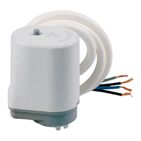
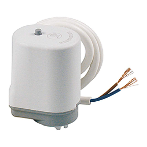
• R473 thermo-electric actuators are equipped with a 2-conductors wire to
connect them to ambient thermostats or control units.
• R473M thermo-electric actuators are equipped with a 4-conductors wire for
a stroke-end micro switch to control circulators or zone valves (brown: phase -
blue: neutral- black and grey: micro switch).
Position mechanical indicator
R473 and R473M thermo-electric actuators include a position mechanical
indicator (A) on the top which enables to visually identify the current position
of the actuator and the valve it serves.
The actuator opens the valve when electrically powered.
The position indicator (A) is lifted up when the valve is open.
The position indicator is particularly useful during testing to perform
operation verications without activating the system or disassembling the
actuator.
A
Lifted position indicator =
thermo-electric actuator and
valve it serves open
A
Lowered position indicator =
thermo-electric actuator and
valve it serves closed
Manual locking lever
For an easier installation on valves and/or manifolds, R473 and R473M
thermo-electric actuators feature a red manual locking lever.
Warning.
Once the actuators are installed on the valves and/or manifolds, the
manual locking lever must be pushed in.
B
Thermo-electric actuator with lever
(B) extending from the actuator.
B
After installation,
manually push the lever (B)
inside the actuator.
Description
Thermo-electric actuators installed on distribution manifolds, radiator
thermostatizable valves or fan coil units enable to adequately control the
ambient temperature by combining energy saving to high levels of comfort.
The R473 and R473M thermo-electric actuators feature absolute operational
quietness, a long life as they have no mechanical parts subject to wear and tear
and a proper slowed-down closing system to prevent water hammer eects.
The activation mechanism includes wax bulbs controlled by low-
consumption electrical PTCs.
Versions and product codes
Series Product code Voltage Characteristics
R473
R473X221 230 V
2-conductors wire
R473X222 24 V
R473M
R473MX221 230 V 4-conductors wire,
with stroke-end micro switch
R473MX222 24 V
Technical data
• Complies with EMC and B.T. directive provisions.
• Status without voltage: normally closed (N.C.)
• Rapid connection for Giacomini standard valves and/or manifolds
• Position mechanic indicator
• Linear movement
• Actuator useful stroke: 2,4 mm
• Pollution class: II
• Nominal pulse voltage: 4 kV
• Protection class: IP40
• Protection against direct contacts through double insulation (Class II)
• Power wire: H03 VV-F; useful length 1 m
• Opening and closing time at 20 °C: ~ 6 mins.
• Room temperature of use: -5÷50 °C
• Storage room temperature: -20÷65 °C
• Max. temperature for device installation surface: 90 °C
• PBT self-extinguishing case material V0-UL94
• Normally open micro switch with closed valve (only for versions with stroke-
end micro switch)
R473 R473M
This appliance should not be operated
by children younger than 8 years, people
with reduced physical, sensory or mental
capacities, or inexperienced people who are
not familiar with the product, unless they
are given close supervision or instructions
on how to use it safety and are made aware
by a responsible person of the dangers its
use might entail.
Children must not play with the appliance.
It is the user’s responsibility to clean and
mantain the appliance. Children should
never clean or mantain it unless they are
given supervision.
2
0813EN November 2016
Thermo-elecTric acTuaTors
Thermo-elecTric acTuaTors Normally closed
r473, r473m
Warning.
• The actuator case cannot be disassembled and should never be
opened.
• Tampering immediately voids the warranty.
• The power wire is not replaceable; if the cable is damaged, replace
the actuator.
• Electrical connections must be carried out by qualied personnel
and voltage-free after carefully verifying the voltage which must
comply with the one specied.
• Connection of power wires to the x distribution network must be
performed in a safe manner as provided for by the Technical Rules in
force in the Country of use.
• Giacomini S.p.A. will not be held responsible for damages suered
by individuals or objects for misuse of the product.
Dimensions
CD
A
B
A [mm] B [mm] C [mm] D [mm]
71 68 51 37
Installation
R473 and R473M thermo-electric actuators may be installed on
thermostatizable valves and/or manifolds with Giacomini standard
connections, using the special toothed ring provided with the actuators.
They can be installed horizontally or vertically, but not upside down with the
indicator pointing downwards.
To install the actuators on valves and/or manifolds, follow the steps below:
C
1Install the toothed ring
(C) on the Giacomini standard
connection valve and/or manifold
pushing down.
Connect the thermo-electric
actuator to the ring.
15° 2Turn the thermo-electric
actuator by 15° clockwise till you
hear a locking click (to remove
the actuator, turn by 15° in
anticlockwise direction).
3Push the red manual locking
lever in.
Important!
4Electrically connect the
actuator according to the
electrical diagrams.
3
0813EN November 2016
Thermo-elecTric acTuaTors
Thermo-elecTric acTuaTors Normally closed
r473, r473m
Electrical data
Product code Absorbed power Voltage Max. peak current (*) Current absorbed
after 12 mins. (*) Resistance (*) Power wire section Micro switch
R473X221 2,5 W 230 V 50Hz ≤ 0,25 A ≤ 0,015 A 6300 Ω ± 1800 Ω 2 x 0,50 mm2-
R473X222 2,5 W 24 V 50 Hz ≤ 0,35 A ≤ 0,125 A 115 Ω ± 28,75 Ω 2 x 0,50 mm2-
R473MX221 2,5 W 230 V 50Hz ≤ 0,25 A ≤ 0,015 A 6300 Ω ± 1800 Ω 4 x 0,50 mm25 A 125 Vac
3 A 250 Vac
R473MX222 2,5 W 24 V 50 Hz ≤ 0,35 A ≤ 0,125 A 115 Ω ± 28,75 Ω 4 x 0,50 mm25 A 125 Vac
3 A 250 Vac
(*) Values read at room temperature
Electrical connections
Avvertenza.
On the supply circuit, a fuse or a protection device external to the device, has to be installed to intervene in case of fault/short circuit conditions.
R473 thermo-electric actuators provide for various connection options able to satisfy a wide range of installation needs. The most frequent cases require simple
direct connections to ambient thermostats or interposition of relays to control the circulators or zone valves.
Termostati ambiente / Room thermostats
NC C NO NC C NO NC C NO
L1
L2
N2
N1
N1N1N1 R2 R3
R1
R2
R3
R1
R473X221
230 Vac
2,5W
R473X222
24 Vac
2,5W
R473M thermo-electric actuators equipped with a stroke-end micro switch enable to easily activate circulators or zone valves. They are generally connected to
ambient thermostats taking into consideration that the R473M is closed when there is no voltage (while the micro switch is electrically open in such status).
To control signicant power loads, we recommend installing a relay to prevent overloading of the actuator micro switches.
L1
L2
N1
N2
N3
L3
R1
R1
R473MX221
230 Vac
MAX 5A 125Vac
MAX 3A 250Vac
MAX 3A 250Vac
2,5W
R473MX222
24 Vac
MAX 5A 125Vac
2,5W
Termostati ambiente / Room thermostats
NC C NO NC C NO NC C NO
Product specications
R473
Thermo-electric actuator normally closed for thermostatizable valves and/or manifolds. 2-conductors wire, length 1 m. Protection class IP40. Rapid connection.
Position mechanic indicator. Room temperature range -5÷50 °C. Available with 230 V or 24 V power. Complies with Directives EMC and B.T.
R473M
Thermo-electric actuator normally closed for thermostatizable valves and/or manifolds. 4-conductors wire, length 1 m. Protection class IP40. Rapid connection.
Position mechanic indicator. Room temperature range -5÷50 °C. Available with 230 V or 24 V power. Complies with Directives EMC and B.T.
4
0813EN November 2016
Thermo-elecTric acTuaTors
Thermo-elecTric acTuaTors Normally closed
r473, r473m
Additional information
For additional information please check the website www.giacomini.com or contact the technical service: '+39 0322 923372 6+39 0322 923255 *[email protected]
This pamphlet is merely for information purposes. Giacomini S.p.A. retains the right to make modications for technical or commercial reasons, without prior notice, to the items described in
this pamphlet. The information described in this technical pamphlet does not exempt the user from following carefully the existing regulations and norms on good workmanship.
Giacomini S.p.A. Via per Alzo, 39 - 28017 San Maurizio d’Opaglio (NO) Italy

This manual suits for next models

5

Other Giacomini Controllers manuals

Giacomini R557RY045 User manual

Giacomini

Giacomini R557RY045 User manual

Giacomini R473 User manual

Giacomini

Giacomini R473 User manual

Giacomini K270Y101 User manual

Giacomini

Giacomini K270Y101 User manual

Giacomini KLIMAdomotic KPM45 Air User manual

Giacomini

Giacomini KLIMAdomotic KPM45 Air User manual

Giacomini K275Y013 User manual

Giacomini

Giacomini K275Y013 User manual

Giacomini K270Y101 User manual

Giacomini

Giacomini K270Y101 User manual

Giacomini Giacoklima Series Guide

Giacomini

Giacomini Giacoklima Series Guide

Giacomini K275-1 User manual

Giacomini

Giacomini K275-1 User manual

Giacomini K274Y082 User manual

Giacomini

Giacomini K274Y082 User manual

Giacomini K274-2 Series User manual

Giacomini

Giacomini K274-2 Series User manual

Giacomini R478 Guide

Giacomini

Giacomini R478 Guide

Giacomini PM100W User manual

Giacomini

Giacomini PM100W User manual

Giacomini K282X022 User manual

Giacomini

Giacomini K282X022 User manual

Giacomini K275Y011 User manual

Giacomini

Giacomini K275Y011 User manual

Popular Controllers manuals by other brands

YASKAWA MP2000 Series Technical note

YASKAWA

YASKAWA MP2000 Series Technical note

Panasonic SQ4-C11 instruction manual

Panasonic

Panasonic SQ4-C11 instruction manual

hager TX502 manual

hager

hager TX502 manual

Emerson CASH VALVE B Installation instruction

Emerson

Emerson CASH VALVE B Installation instruction

FUJI CONTROLS CP-2 instruction manual

FUJI CONTROLS

FUJI CONTROLS CP-2 instruction manual

Mitsubishi Electric MELSEC-A Series user manual

Mitsubishi Electric

Mitsubishi Electric MELSEC-A Series user manual

Primex PrimexEVENT Series installation guide

Primex

Primex PrimexEVENT Series installation guide

Siko AG24 installation instructions

Siko

Siko AG24 installation instructions

Salus THB23030 quick guide

Salus

Salus THB23030 quick guide

Taie FY series Operation manual

Taie

Taie FY series Operation manual

EWS OS 3030 instruction manual

EWS

EWS OS 3030 instruction manual

ABB PSTX Series user manual

ABB

ABB PSTX Series user manual

BIFFI HLA Installation, operation and maintenance manual

BIFFI

BIFFI HLA Installation, operation and maintenance manual

Fluidwell F131-P manual

Fluidwell

Fluidwell F131-P manual

Siemens SIDOOR AT40 System manual

Siemens

Siemens SIDOOR AT40 System manual

Aficio AP1015 operating instructions

Aficio

Aficio AP1015 operating instructions

SCHOTT VisiLED MC 1500 manual

SCHOTT

SCHOTT VisiLED MC 1500 manual

Norac CS02 installation manual

Norac

Norac CS02 installation manual

manuals.online logo
manuals.online logoBrands
  • About & Mission
  • Contact us
  • Privacy Policy
  • Terms and Conditions

Copyright 2025 Manuals.Online. All Rights Reserved.