manuals.online logo
Brands
  1. Home
  2. •
  3. Brands
  4. •
  5. Giacomini
  6. •
  7. Controllers
  8. •
  9. Giacomini K282X022 User manual

Giacomini K282X022 User manual

1
0825EN August 2018
ActuAtor for mixing vAlves
3-point floating actuator (connection M30 x1,5 mm)
with integrated regulator
for r298 and r298n Mixing valves - K281 series
047U54728
Description
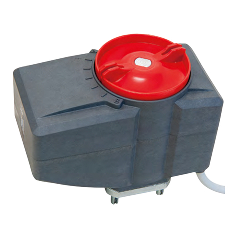
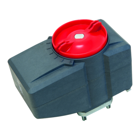
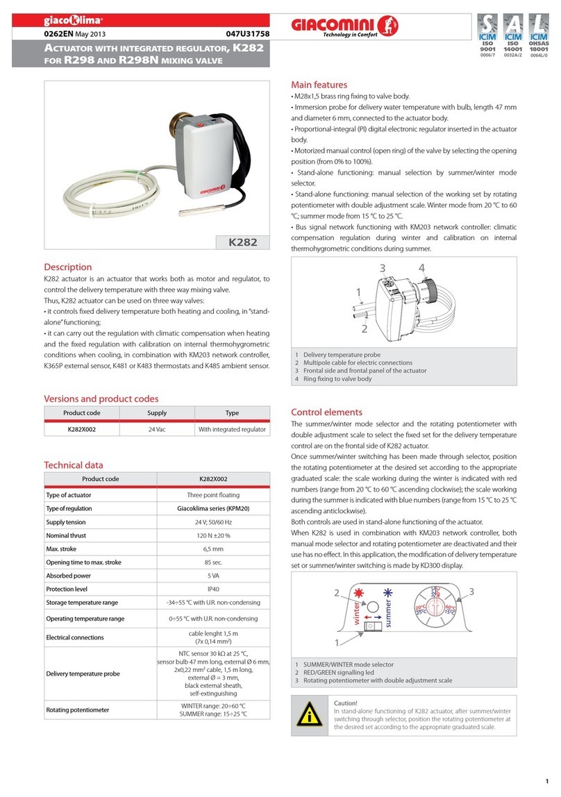
K282X022 is an actuator that works both as motor and regulator, to control
the delivery temperature with three way mixing valve.
The actuator can be used on three way valves: it controls xed delivery
temperature both heating and cooling, in“stand-alone”functioning;
Versions and product codes
Product code Supply Type Valve connection
K282X022 24 Vac 3-point oating
with integrated regulator M30 x 1,5 mm
Technical data
• Type of actuator: 3-point oating
• Power supply: 24 V 50/60 Hz
• Type of command: automatic only
• Propulsion force: 120 N ±20 %
• Maximum stroke: 6,5 mm
• Opening time at maximum speed: 85 sec
• Electricity absorption: 5 VA
• Protection class: IP40
• Storage temperature range: -34÷55 °C with R.H non-condensing
• Operating ambient temperature range: 0÷55 °C with R.H non-condensing
• Electric cable length: 1,5 m (7 x 0,14 mm2)
• Ring nut for xing to valve body: M30x1,5 mm, in brass
• Delivery temperature probe:
NTC sensor 30 kΩ at 25 °C,
sensor bulb 47 mm long, external Ø 6 mm
2x0,22 mm2cable, 1,5 m long, external Ø = 3 mm,
• Black external sheath, self-extinguishing
• Dual color LED (green/red), function status indicator
• Color: white/grey
Main features
• M30x1,5 mm brass ring xing to valve body.
• Immersion probe for delivery water temperature with bulb, length 47 mm
and Ø 6 mm, connected to the actuator body.
• Proportional-integral (PI) digital electronic regulator inserted in the actuator
body.
• Motorized manual control (open ring) of the valve by selecting the opening
position (from 0% to 100%).
• Stand-alone functioning: manual selection by summer/winter mode selector.
• Stand-alone functioning: manual selection of the working set by rotating
potentiometer with double adjustment scale. Winter mode from 20 °C to 60
°C; summer mode from 15 °C to 25 °C.
34
1
2
Legend
1Delivery temperature probe
2Multipole cable for electric connections
3Frontal side and frontal panel of the actuator
4Ring xing to valve body
Control elements
winter
20°C
25°C
20°C
40°C
60°C
15°C
summer
2
1
3
Legend
1SUMMER/WINTER mode selector
2RED/GREEN signalling led
3Rotating potentiometer with double adjustment scale
The summer/winter mode selector and the rotating potentiometer with
double adjustment scale to select the xed set for the delivery temperature
control are on the frontal side of K282 actuator.
Once summer/winter switching has been made through selector, position
the rotating potentiometer at the desired set according to the appropriate
graduated scale: the scale working during the winter is indicated with red
numbers (range from 20 °C to 60 °C ascending clockwise); the scale working
during the summer is indicated with blue numbers (range from 15 °C to 25 °C
ascending anticlockwise).
Warning.
In stand-alone functioning of K282 actuator, after summer/winter
switching through selector, position the rotating potentiometer at
the desired set according to the appropriate graduated scale.
K282X022
2
0825EN August 2018
ActuAtor for mixing vAlves
3-point floating actuator (connection M30 x1,5 mm)
with integrated regulator
for r298 and r298n Mixing valves - K281 series
047U54728
Addressing
1
2
3
4
6
7
8
2
1
1
2
1234678
Legend
1Jumper for manual control (open ring) of the actuator
28 way microswitch for actuator addressing
The addressing through microswitch with several ways is not relevant when
K282 actuator is used as single device (stand-alone conguration): it is not
necessary to make any conguration in this application.
All microswitch sliders are positioned on “OFF” (side with 1-8 numbers)
on delivery. K282 actuator uses selectors from 1 to 6 to assign an address
between 0 and 31: check the address to assign on the design documentation
of the system.
Position of microswitch ways
Addr. 1 2 3 4 5 6
0OFF OFF OFF OFF OFF OFF
1ON OFF OFF OFF OFF OFF
2OFF ON OFF OFF OFF OFF
3ON ON OFF OFF OFF OFF
4OFF OFF ON OFF OFF OFF
5ON OFF ON OFF OFF OFF
6OFF ON ON OFF OFF OFF
7ON ON ON OFF OFF OFF
8OFF OFF OFF ON OFF OFF
9ON OFF OFF ON OFF OFF
10 OFF ON OFF ON OFF OFF
11 ON ON OFF ON OFF OFF
12 OFF OFF ON ON OFF OFF
13 ON OFF ON ON OFF OFF
14 OFF ON ON ON OFF OFF
15 ON ON ON ON OFF OFF
16 OFF OFF OFF OFF ON OFF
17 ON OFF OFF OFF ON OFF
18 OFF ON OFF OFF ON OFF
19 ON ON OFF OFF ON OFF
20 OFF OFF ON OFF ON OFF
21 ON OFF ON OFF ON OFF
22 OFF ON ON OFF ON OFF
23 ON ON ON OFF ON OFF
24 OFF OFF OFF ON ON OFF
25 ON OFF OFF ON ON OFF
26 OFF ON OFF ON ON OFF
27 ON ON OFF ON ON OFF
28 OFF OFF ON ON ON OFF
29 ON OFF ON ON ON OFF
30 OFF ON ON ON ON OFF
31 ON ON ON ON ON OFF
Warning.
Make sure that the assigned address is correct: it is not possible to
have two devices with the same address in the same system.
Signalling elements
The led on the frontal side of actuator provides status information.
• Fixed red: indicates stand-alone functioning in WINTER mode.
• Fixed green: indicates stand-alone functioning in SUMMER mode.
Electrical connection
SHUTOFF
K282 24V
50/60 Hz
5VA
SENSOR
DELIVERY TEMP.
BLU
WHITE
GREEN
YELLOW
V
Com
RT-
RT+
GRAY
24V
BUS
BROWN
SHUTOFF PINK
Conductor colour Function
BROWN (marrone) 24 V~ supply connection
GRAY (grigio) 24 V~ supply connection
When 24 V supply is activated to K282 actuator, the integrated electronic
regulator starts a cycle of adjustment in which the stem of the actuator
is led to complete by-pass position (the whole stem has gone back in the
actuator body).
Connection to bus
Warning.
The connection to the Bus conductor is compatible only with the
Giacoklima thermoregulation (KPM20 regulator and accessories)
Warning.
Before connecting K282 actuator, make sure that network tension IS
NOT CONNECTED and that it corresponds to the one written on the
back of the device (24 V~). The device must be installed by qualied
sta only.
Conductor color Function
YELLOW (giallo) RT+ Signal (RS485 standard)
GREEN (verde) RT- Signal (RS485 standard)
WHITE (bianco) Com Common (signal + supply)
BLUE (blu) V SELV supply
3
0825EN August 2018
ActuAtor for mixing vAlves
3-point floating actuator (connection M30 x1,5 mm)
with integrated regulator
for r298 and r298n Mixing valves - K281 series
047U54728
Installation
1) Unscrew the handwheel protecting body before assembling and adjust
the shutter manually on R298 or R298N valve.
2) Fix K282X022 actuator through its apposite brass xing ring: the ring
must be screwed to the valve body up to end stroke in order to ensure max.
stroke to the shutter.
3) Insert the immersion probe in a R227 pit, downstream of the secondary
circulator, and block by means of the xing screw.
Positions of the linear stem of the actuator
The action of the digital regulator integrated in K282X022 actuator
associates the stem completely retracted to the position of complete
closure (0%) as shown in the picture; the stem completely protruding from
the actuator body is associated to the position of complete opening (100%).
Stelo ritratto,
posizione di by-pass
della valvola miscelatrice R298
Stelo sporgente,
posizione di apertura della via diretta
della valvola miscelatrice R298
Correct installation positions of K282 actuator
Dimensions
BC
A
M30x1,5 mm
Codice A [mm] B [mm] C [mm]
K282X022 70 78 48
Reference standards
• CE marked
• EMC 2004/108/CE
• Low voltage directive 2006/95/CE
Motorized manual control of the valve
1
2
3
4
6
7
8
2
1
1
2
1234678
Legend
1Jumper for manual control (open ring) of the actuator
28 way microswitch for actuator addressing
The manual positioning (open ring) of the mixing valve is useful when
starting a system or in order to check the functioning. This operation can
be made with K282 actuator by extracting the apposite jumper on the
board, after removing the upper shell: the rotating potentiometer position
represents the required opening for the mixing valve in this manual state
of functioning. The opening of the direct way from the boiler of the valve
increases by rotating the potentiometer clockwise when Giacomini mixing
valves are used. The stem of the actuator is completely retracted (0%) and
the mixing valve closes the direct way completely (by-pass position), when
the rotating potentiometer is completely rotated anticlockwise; the stem of
the actuator is protruding (100%) and the mixing valve opens the direct way
completely, when potentiometer is completely rotated clockwise.
For the manual positioning:
1) Remove 24 V~ supply to K282 actuator.
2) Loosen the actuator ring xing to valve body and unscrew the actuator
completely.
3) Remove the upper shell of the actuator by removing the 4 xing screws.
4) Extract the jumper placed on the electronic board as shown in the picture.
5) Position the upper shell of the actuator again through the 4 xing screws.
6) Assemble K282X022 actuator on the valve body again.
7) Activate 24 V~ supply. The actuator resets completely until it closes the
direct way completely (0%). The actuator positions at the indicated opening
through the rotating potentiometer.
When the functioning test is nished, follow the instructions and insert the
jumper placed on the electronic board.
Warining.
Manual positioning tests of the valve must be carried out once
the jumper on the electronic board has been extracted and after
assembling again and xing with the 4 apposite screws the upper
shell of the actuator. Do not activate 24 V~ supply before assembling
the upper shell again. The manual positioning of the valve must be
carried out by qualied sta only.
Warining.
The reading of immersion delivery temperature probe is not taken
into account during the manual positioning test of the valve. Make
sure that the delivery temperature is not over or under the safety
limits according to the kind of system. The manual positioning of the
valve must be carried out by qualied sta only.
4
0825EN August 2018
ActuAtor for mixing vAlves
3-point floating actuator (connection M30 x1,5 mm)
with integrated regulator
for r298 and r298n Mixing valves - K281 series
047U54728
IT AVVERTENZE PER IL CORRETTO SMALTIMENTO DEL PRODOTTO
Questoprodottorientranelcampo di applicazione dellaDirettiva2012/19/UEriguardantelagestione dei riutidiapparecchiatureelettricheedelettroniche(RAEE).
L’apparecchio non deve essere eliminato con gli scarti domestici in quanto composto da diversi materiali che possono essere riciclati presso le strutture adeguate.
Informarsi attraverso l’autorità comunale per quanto riguarda l’ubicazione delle piattaforme ecologiche atte a ricevere il prodotto per lo smaltimento ed il suo
successivocorrettoriciclaggio.Siricorda,inoltre,cheafrontediacquistodiapparecchioequivalente,ildistributoreètenutoalritiro gratuitodel prodottoda smaltire.
Il prodotto non è potenzialmente pericoloso per la salute umana e l’ambiente, ma se abbandonato nell’ambiente impatta negativamente sull’ecosistema.
Leggere attentamente le istruzioni prima di utilizzare l’apparecchio per la prima volta. Si raccomanda di non usare assolutamente il prodotto per un uso diverso
da quello a cui è stato destinato, essendoci pericolo di shock elettrico se usato impropriamente.
Il simbolo del bidone barrato, presente sull’etichetta posta sull’apparecchio, indica la rispondenza di tale prodotto alla normativa relativa ai riuti di
apparecchiature elettriche ed elettroniche.
L’abbandono nell’ambiente dell’apparecchiatura o lo smaltimento abusivo della stessa sono puniti dalla legge.
EN IMPORTANT INFORMATION FOR CORRECT DISPOSAL OF THE PRODUCT
This product falls into the scope of the Directive 2012/19/EU concerning the management of Waste Electrical and Electronic Equipment (WEEE).
This product shall not be dispose in to the domestic waste as it is made of dierent materials that have to be recycled at the appropriate facilities.
Inquire through the municipal authority regarding the location of the ecological platforms to receive the product for disposal and its subsequent correct recycling.
Furthermore, upon purchase of an equivalent appliance, the distributor is obliged to collect the product for disposal free of charge.
The product is not potentially dangerous for human health and the environment, but if abandoned in the environment can have negative impact on the
environment. Read carefully the instructions before using the product for the rst time. It is recommended that you do not use the product for any purpose
rather than those for which it was intended, there being a danger of electric shock if used improperly.
The crossed-out wheeled dustbin symbol, on the label on the product, indicates the compliance of this product with the regulations regarding Waste
Electrical and Electronic Equipment.
Abandonment in the environment or illegal disposal of the product is punishable by law.
FR AVERTISSEMENTS POUR L’ÉLIMINATION CORRECTE DU PRODUIT
Ce produit entre dans le champ d’application de la directive 2012/19 / UE relative à la gestion des déchets équipements électriques et électroniques (DEEE).
L’appareil ne doit pas être jeté avec les ordures ménagères car il est fait de diérents matériaux pouvant être recyclés dans des centres appropriés.
Renseignez-vous auprès de l’autorité locale concernant l’emplacement des plates-formes écologiques appropriées pour recevoir le produit pour sa destruction
et son recyclage correct ultérieur. Il convient également de rappeler que, en cas d’achat d’un appareil équivalent, le distributeur est tenu de collecter le produit
à détruire. Le produit n’est potentiellement pas dangereux pour la santé humaine et l’environnement, mais s’il est abandonné dans l’environnement, il a un
impact négatif sur l’écosystème. Lisez attentivement les instructions avant d’utiliser l’appareil pour la première fois.
Il est interdit d’utiliser le produit pour un usage diérent de celui auquel il était destiné, il y a risque de choc électrique si utilisé incorrectement.
Le symbole de la poubelle barrée sur l’étiquette de l’appareil indique sa correspondance produit à la législation relative aux déchets d’équipements
électriques et électroniques.
L’abandon dans l’environnement de l’équipement ou l’élimination illégale de l’équipement est punissable par la loi.
DE WICHTIGE HINWEISE ZUR KORREKTEN ENTSORGUNG DES PRODUKTS
Dieses Produkt fällt in den Anwendungsbereich der Richtlinie 2012/19/EU über die Entsorgung von Elektro- und Elektronik - Altgeräten (WEEE).
Dieses Produkt darf nicht in den Hausmüll entsorgt werden, da es aus verschiedenen Materialien besteht, die in entsprechenden Einrichtungen recycelt werden
müssen. Erkundigen sie sich bei ihrer Gemeinde nach dem Standort des nächsten Recyclinghofs bzw. der nächsten Annahmestelle, um das Produkt dem
Recycling zuzuführen bzw. fachgerecht zu entsorgen. Darüber hinaus ist der Händler verpichtet, das Produkt beim Kauf eines gleichwertigen Geräts kostenlos zu
entsorgen. Das Produkt ist für die menschliche Gesundheit und die Umwelt potenziell nicht gefährlich. Diese können sich aber, falls sie in der Umwelt gelangen,
negativ auf diese auswirken. Lesen Sie daher vor dem ersten Gebrauch des Produkts die Inbetriebnahme-, Bedienungs- und Entsorgungsanweisungen sorgfältig
durch. Es wird empfohlen, dass Sie das Produkt nur für den vorgesehenen Zweck verwenden.
Bei unsachgemäßer Verwendung bzw. Fehlgebrauch besteht die Gefahr eines elektrischen Schlags.
Das Symbol der durchgestrichenen Mülltonne auf dem Etikett des Produkts weist auf die Konformität dieses Produkts zu den Vorschriften für Elektro-
und Elektronik-Altgeräte hin. Das Ablagern in der Umwelt oder die illegale Entsorgung des Produkts ist strafbar.
Additional information
For more information, go to www.giacomini.com or contact our technical assistance service: '+39 0322 923372 6+39 0322 923255 *[email protected]
This document provides only general indications. Giacomini S.p.A. may change at any time, without notice and for technical or commercial reasons, the items included herewith.
The information included in this technical sheet do not exempt the user from strictly complying with the rules and good practice standards in force.
Giacomini S.p.A. Via per Alzo, 39 - 28017 San Maurizio d’Opaglio (NO) Italy

Other Giacomini Controllers manuals

Giacomini K274Y082 User manual

Giacomini

Giacomini K274Y082 User manual

Giacomini R478 Guide

Giacomini

Giacomini R478 Guide

Giacomini K270Y101 User manual

Giacomini

Giacomini K270Y101 User manual

Giacomini K270Y101 User manual

Giacomini

Giacomini K270Y101 User manual

Giacomini R473 User manual

Giacomini

Giacomini R473 User manual

Giacomini K275-1 User manual

Giacomini

Giacomini K275-1 User manual

Giacomini R557RY045 User manual

Giacomini

Giacomini R557RY045 User manual

Giacomini Giacoklima Series Guide

Giacomini

Giacomini Giacoklima Series Guide

Giacomini KLIMAdomotic KPM45 Air User manual

Giacomini

Giacomini KLIMAdomotic KPM45 Air User manual

Giacomini K275Y013 User manual

Giacomini

Giacomini K275Y013 User manual

Giacomini R473 Series User manual

Giacomini

Giacomini R473 Series User manual

Giacomini PM100W User manual

Giacomini

Giacomini PM100W User manual

Giacomini K275Y011 User manual

Giacomini

Giacomini K275Y011 User manual

Giacomini K274-2 Series User manual

Giacomini

Giacomini K274-2 Series User manual

Popular Controllers manuals by other brands

Vageo V-DCS3 manual

Vageo

Vageo V-DCS3 manual

Smartgen HGM9510 user manual

Smartgen

Smartgen HGM9510 user manual

Rockwell Automation Allen-Bradley MicroLogix 1400 Series user manual

Rockwell Automation

Rockwell Automation Allen-Bradley MicroLogix 1400 Series user manual

Moeller Marine EASY 600 Product information

Moeller Marine

Moeller Marine EASY 600 Product information

Crestron DM-RMC-4K-100-C-1G quick start

Crestron

Crestron DM-RMC-4K-100-C-1G quick start

Mitsubishi Electric MELSEC iQ-F FX5 user manual

Mitsubishi Electric

Mitsubishi Electric MELSEC iQ-F FX5 user manual

LINK-MI LM-TV04B user manual

LINK-MI

LINK-MI LM-TV04B user manual

Culligan GBE Installation, operating and service instructions

Culligan

Culligan GBE Installation, operating and service instructions

Innovate Motorsports LC-1 user manual

Innovate Motorsports

Innovate Motorsports LC-1 user manual

Johnson Controls DS-3153 Installation

Johnson Controls

Johnson Controls DS-3153 Installation

Numark NuVJ Quick start manual

Numark

Numark NuVJ Quick start manual

Voltech ISC3020 Installation and operating instructions

Voltech

Voltech ISC3020 Installation and operating instructions

MICRO-AIR EASYSTART installation instructions

MICRO-AIR

MICRO-AIR EASYSTART installation instructions

Lawler 804 SEA Basic manual

Lawler

Lawler 804 SEA Basic manual

Sherwood Scuba maximus SRB5600 Assembly & maintenance guide

Sherwood Scuba

Sherwood Scuba maximus SRB5600 Assembly & maintenance guide

Sentinel CO2-EXP instruction manual

Sentinel

Sentinel CO2-EXP instruction manual

Rohde TC 304 instruction manual

Rohde

Rohde TC 304 instruction manual

Panasonic AG-A850 Specifications

Panasonic

Panasonic AG-A850 Specifications

manuals.online logo
manuals.online logoBrands
  • About & Mission
  • Contact us
  • Privacy Policy
  • Terms and Conditions

Copyright 2025 Manuals.Online. All Rights Reserved.