0548-991-01---10i_2022.05.indd
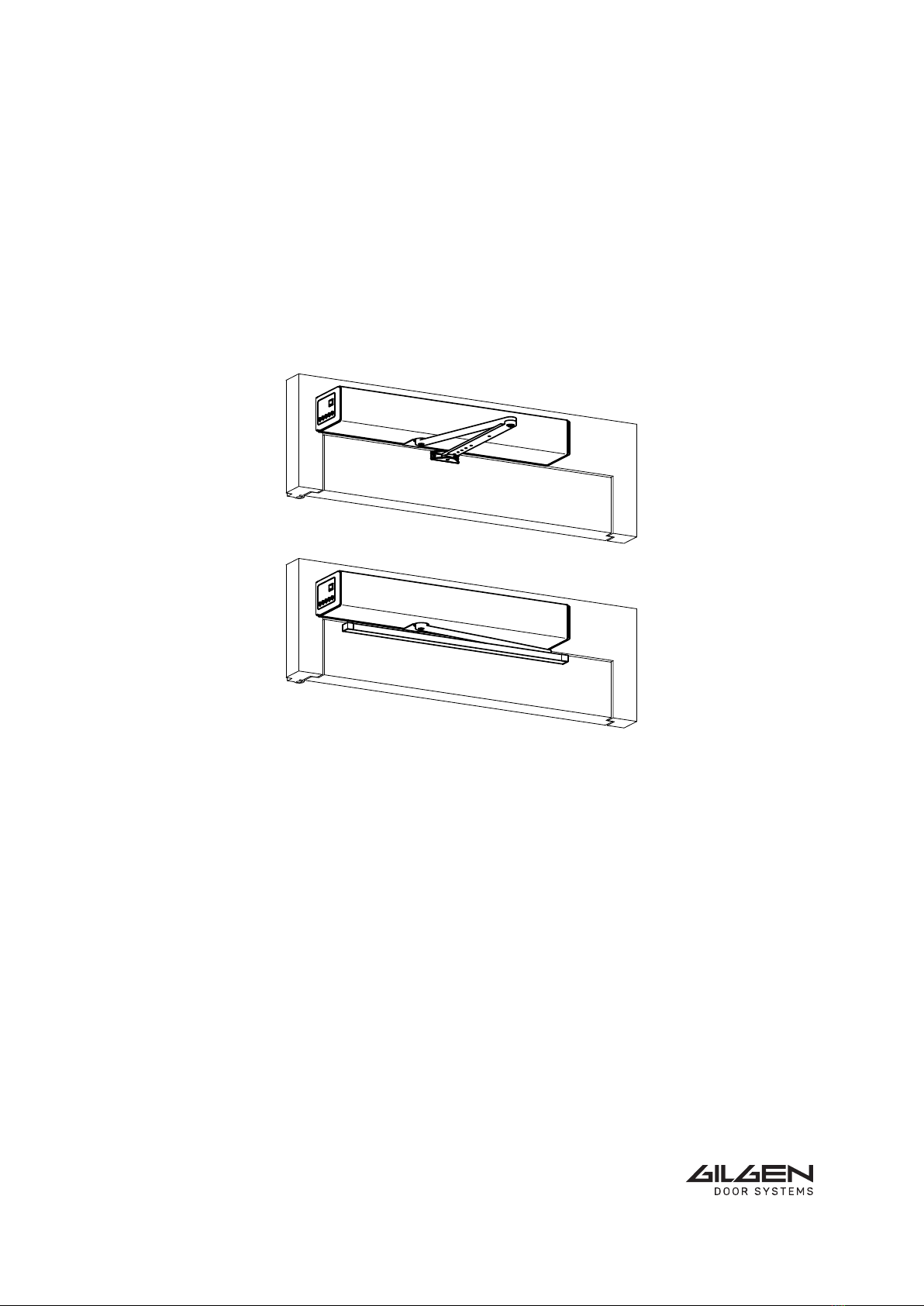
FD 20
0548-991/02i
Page 2 of 26
Operator manual
TABLE OF CONTENTS
1 GENERAL REMARKS ................................................................................................................ 4
1.1 Target group................................................................................................................... 4
1.2 Where to keep the operator manual ............................................................................. 4
1.3 Adresses......................................................................................................................... 4
2 SAFETY...................................................................................................................................... 5
2.1 Appropriate use ............................................................................................................. 5
................................................................................................................. 5
.......................................................................................................... 5
2.3.1 Principles......................................................................................................... 5
2.3.2 Service............................................................................................................. 6
.................................................................................................. 6
................................................................................................... 6
2.3.5 Accessories/Spare parts .................................................................................. 6
................................................................... 6
3 PRODUCT DESCRIPTION ......................................................................................................... 7
3.1 General remarks ............................................................................................................ 7
3.2 ...................................................................................................... 8
......................................................................................................... 8
.............................................................................. 9
3.5 Control elements ........................................................................................................... 9
............................................................................................................. 9
3.7 Technical data .............................................................................................................. 10
4 CONTROL................................................................................................................................ 11
4.1 Main switch.................................................................................................................. 11
4.2 Program selector.......................................................................................................... 11
......................................................................................................... 12
.......................................................................................................... 13
............................................................................................................... 13
......................................................................................................... 13
........................................................................................... 14
.......................................................................... 14
4.4.5 Menu level .................................................................................................... 15
........................................................................................... 16
.................................................................................................. 17
.............................................................................................. 18
5 SERVICE .................................................................................................................................. 19
........................................................ 19
.................................................................................................. 19
5.1.2 Care ............................................................................................................... 19
5.1.3 Checking........................................................................................................ 20
..................................... 20