0630-999-22b_2004.12.p65 0630-999/22b
SLM
3-8
DE
15 14 13 16 17
11
12
1
8/9
7
10
8
8. Seitenteile (1) unten auf vorgegebene Lichte Weite LW ein-
stellen und Lagerwinkel (7) mittels Senkschraube (8) und
Senk-Unterlagsscheibe(9)aufBodenführung(10)festschrau-
ben.
9. Zylinderschraube (11) mit U-Scheibe und Distanzrohr (12)
entfernen (Transportsicherung).
10. KontrollierenobSeitenteil(1)obenimLotundaufvorgegebe-
nerLichtenWeiteLWist. Falls notwendig, wiefolgteinstellen:
· Zylinderschrauben In-6kt (13) sowie Gegenmutter (14) lö-
sen.
· Mittels Gewindestift (15) Seitenteil oben einstellen.
· Gegenmutter(14)undZylinderschrauben(13)wiederfest-
ziehen.
11. AbstandSeitenteil(1)zu Bodenführung(10)auf8mmeinstel-
len:
· Gegenmutter (16) lösen und mittels 6kt-Mutter (17)
Abstand einstellen.
· Gegenmutter (16) wieder festziehen.
Kontrolle: Seitenteil (1) darf beim Ausschwenken nicht am
Trägerprofil streifen!
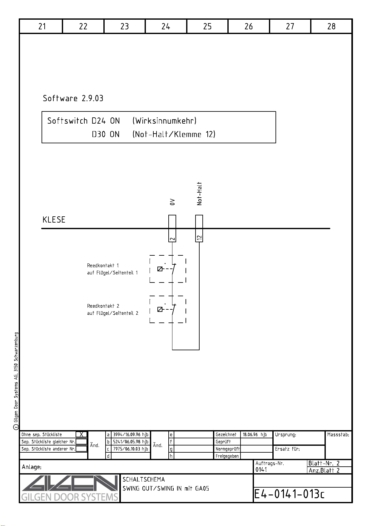
12. Alle elektrischen Kabel in Antriebskasten ziehen und an
Steuerung gemäss Schema anschliessen.
Zusätzlich die Ausschwenküberwachung (Reedkontakt)
gemäss Schema E4-0141-013 im Anhang anschliessen.
13. Öffnungskraft zum Ausschwenken der Seitenteile prüfen und
einstellen. Vorgehen: siehe Kapitel 5.
14. Abdeckbleche über Swing-Out-Beschlag und Tragprofilstück
montieren.
8. Adjust the bottom of the side panels (1) with regard to the
existingclearancewidth(LW)and screw the supportingangle
(7) down to the floor guideway (10), using the flat head screw
(8) and the conical washer (9).
9. Remove the cheese-head screw (11)with thewasher andthe
distance tube (12) (transport protection).
10. Check if the upper part of the side panel (1) is perpendicular
and adjusted to the existing clearance width LW. If required
adjust as follows:
· Unscrewthe hexagon socket cheese-head screws(13) as
well as the counter-nut (14).
· Bymeans of the set screw (15) adjust the upperpart of the
side panel.
· Retighten counter-nut (14) and the cheese-head screws (13).
11. Adjust a distance of 8 mm between the side panel (1) and the
floor guideway (10).
· Loosen the counter-nut (16) and adjust the distance by
means of the hexagon nut (17).
· Retighten the counter-nut (16).
Checking:During the swing-out motion, the side panel (1)
must not brush against the supporting profile!
12. Lay out all the electric cables in the drive case and connect
them to the control according to the diagram.
In addition, connect the swing-out monitoring (Reed contact)
according to diagram E4-0141-013 in the appendix.
13. Check and adjust the opening force for swinging out the side
panels. Procedure: see chapter 5.
14. Mountthesheetmetalcoveringsontopofthe swing-out fitting
and of the supporting profile section.