0552-999-03_05.98.p65 4-4
33
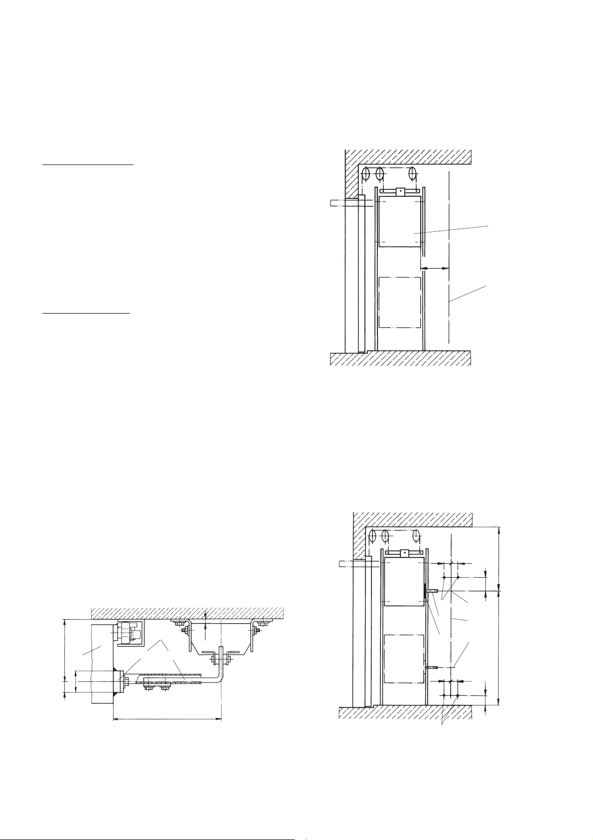
90°
max. 150 N
Fig. 10
Kontrolle der Schliesskraft
Nach der EKAS-Richtlinie 1511 muss die Kraft an der Schliesskante
des Tores auf 150 N begrenzt werden.
- Tor über Impulsgeber schliessen und während des Schliessvor-
gangs manuell anhalten. Bei einer aufzuwendenden Kraft von
max. 150 N muss der Antrieb wieder öffnen. Schematische
Anordnung zur Messung dieser Kraft mittels Federwaage (33)
gemäss Fig. 10.
- Sollte die erforderliche Anhaltekraft 150 N überschreiten, muss
eine Nachjustierung mit Hilfe des BEDIS erfolgen.
Zustandsanzeigen auf der DBL-Steuerung
Auf der Steuerung LED D31 bis D34
• D31 (grün) Öffnungs- oder Schliessbefehl steht an.
• D32 (grün) Halt-Befehl steht an.
• D33 (grün) Reversierbefehl steht an.
• D34 (rot) Systemfehler. Eine detailierte Fehleranalyse kann
durch Fachpersonal mit dem BEDIS vorgenommen
werden.
Funktions- und Bedienungsanleitung
Der Gilgen-Kipptorantrieb kann durch Impulsgeber wie Funkfern-
steuerung, Schlüsselschalter, externe Drucktaster betätigt werden. Es
ist nur eine kurze Impulsgabe erforderlich.
Schrittschaltfunktion AUF-HALT-ZU:
Tor ist geschlossen:
Einmalige Impulsgabe öffnet das Tor.
Tor ist geöffnet:
Einmalige Impulsgabe schliesst das Tor.
Tor in Bewegung:
Einmalige Impulsgabe stoppt das Tor.
Erneuter Impuls bewirkt ein Anlaufen des Tores in die entgegenge-
setzte Richtung.
Sicherheitsautomatik:
Im Schwenkbereich des Tores dürfen sich keine Personen oder Ge-
genstände befinden. Sollte dies durch Unachtsamkeit doch einmal der
Fall sein, bewirkt die Steuerung des Antriebes beim Auflaufen auf ein
Hindernis während des Schliessvorganges ein Reversieren (Um-
schaltbar mit dem BEDIS auf Halt mit Selbstbefreiung). Läuft das Tor
beim Öffnungsvorgang auf ein Hindernis, stoppt der Antrieb sofort und
läuft etwas zu. Beim nächsten Impuls schliesst das Tor wieder.
Bei Überwachung des Torschwenkbereiches durch externe Sicher-
heitselemente (z. B. Lichtschranke, Kontaktleiste) reversiert ein sich
schliessendes Tor sofort wenn sich eine Person oder ein Gegenstand
im Überwachungsbereich des Sicherheitselementes befindet.
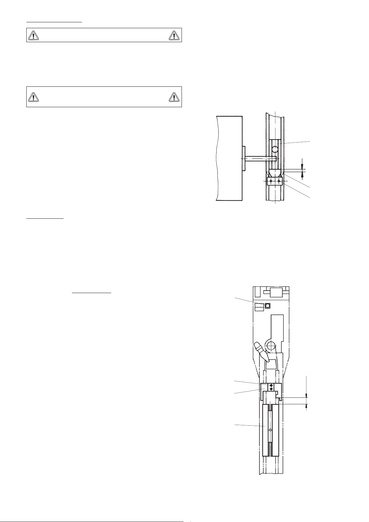
Notentriegelung:
Bei Stromausfall oder sonstigen Störungen kann das Tor durch Dre-
hen des Torgriffes von aussen oder durch Ziehen des roten Knopfes
von innen, entriegelt werden. Der Laufschlitten wird dabei von der
Antriebskette getrennt. Das Tor ist leicht von Hand zu öffnen. Ist die
Störung beseitigt oder der Strom wieder eingeschaltet, läuft die Kette
nach Impulsgabe automatisch in den Laufschlitten ein und das Tor
wird geöffnet.
Beleuchtung:
Werkseitig ist der Antrieb mit einer Fassung E14-230 V und Kerzen-
glühlampe 25 W ausgerüstet.
Die Beleuchtung schaltet sich beim Öffnungsimpuls ein und nach ca.
180 Sek. wieder aus.
Änderungen vorbehalten
Masse in mm
Anhang
Schema .............................................................................. E4-0141-199
Tor schliesst/öffnet nicht vollständig. *
Antrieb lässt sich durch Sendeimpuls nicht aktivieren, kann jedoch
durch Drucktaster oder andere Impulsgeber betätigt werden.
Antrieb lässt sich weder durch Sendeimpuls noch durch andere
Bedienungselemente aktivieren.
Geringe Reichweite der Fernsteuerung.
* Diese Störung kann möglicherweise durch drücken der Reset-Taste behoben werden.
- Leere Batterie auswechseln.
- Standort-Korrektur des Empfängers vornehmen.
- Leere Batterie auswechseln.
- Kabelanschlüsse und Steckverbindungen des Empfängers kon-
trollieren.
- Codierung des Senders und Empfängers gemäss F7000-Anlei-
tung angleichen.
- Prüfen, ob Spannung 230 V an Steckdose anliegt.
- Eventuell Hauptsicherung wieder einschalten.
- Bei losen Kabelanschlüssen bzw. defekten Gerätesicherungen
Netzstecker ziehen und Anschlüsse wieder herstellen, defekte
Gerätesicherungen 2 AT auswechseln.
- Mit BEDIS Motorstromgrenzen neu justieren.
- Tor auskuppeln und Leichtgängigkeit prüfen.
- Läuft Antrieb mit ausgekuppeltem Tor den ganzen Fahrweg?
Tor steuert nicht um, wenn es während des Schliessvorganges auf
Widerstand läuft.
Tor bleibt nicht stehen (Motor schaltet nicht ab), wenn es während
der Öffnungsbewegung auf Widerstand stösst.
Abhilfe (nur durch Sachkundige)Störung
Fehlersuchanleitung