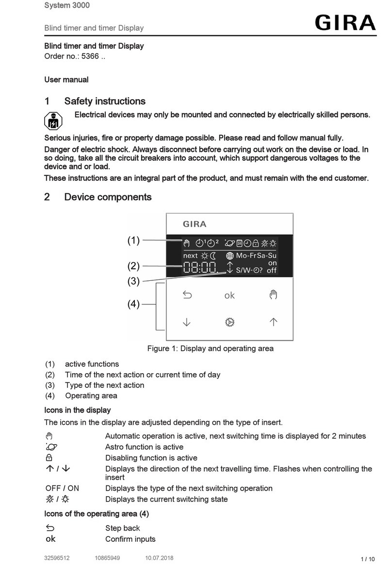
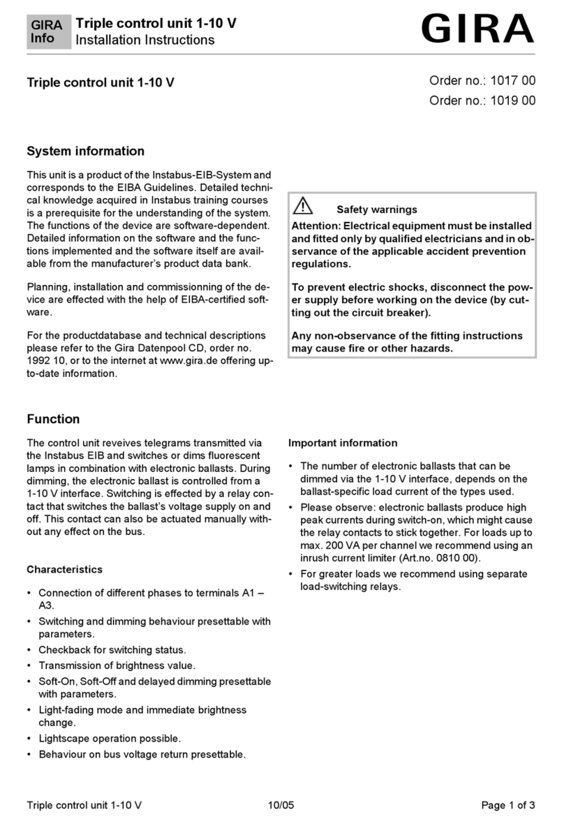
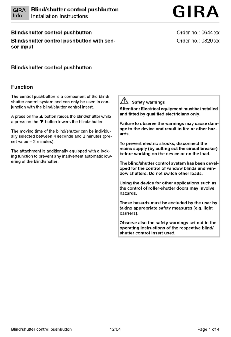
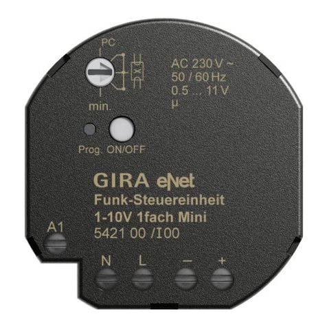
Gira System 3000 User manual

System 3000
Flush-mounted DALI Power control unit insert
Order no.: 5406 00
Operating instructions
1 Safety instructions
Electrical devices may only be mounted and connected by electrically skilled persons.
Serious injuries, fire or property damage possible. Please read and follow manual fully.
Danger of electric shock. Always disconnect before carrying out work on the device or load. In
so doing, take all the circuit breakers into account, which support dangerous voltages to the
device and or load.
These instructions are an integral part of the product, and must remain with the end customer.
2 Intended use
– Switching and brightness setting for luminaires with DALI interface
– Setting the colour temperature for luminaires with DALI Device Type 8 for Tunable White
in accordance with IEC 62386-209
– Mounting in appliance box according to DIN 49073
– Operation with suitable cover
Since error-free interaction cannot be guaranteed in combination with other DALI controls,
it is thus not recommend.
Product characteristics
– DALI supply for a maximum of 18 DALI subscribers
– Parallel switching of up to 4 DALI control units with the option of supplying up to 72 DALI
subscribers
– Storing of minimum brightness, coldest and warmest colour temperature
– Switching on with the last set brightness/colour temperature or saved brightness/colour
temperature
– With 2-channel button cover: Adjustment of the colour temperature via right rocker
3 Operation
These instructions describe operation with a 1-channel button cover. Operation with different
covers is described in the instructions for the cover in question. Operation using 2-wire or 3-wire
extension essentially corresponds to operation on the main device.
With a 2-channel button cover, the left rocker works like the 1-channel button cover. The
right rocker is used to directly set the colour temperature.
Switching the light
■ Brief press on the button cover: Light is switched on or off at the last set brightness/colour
temperature or a saved brightness/colour temperature.
■ Long press on the button cover at the bottom: Light is switched on at minimum brightness.
Adjusting the brightness
■ Long press the button cover at the top or bottom.
Setting the colour temperature
■ Press the button cover in the switched-on state at the top, bottom or over the entire sur-
face twice within 0.4 seconds (double-click). The light switches off and on again.
■ Long press the button cover at the top or bottom.
1 / 6
82598922 19.03.2020

System 3000
Flush-mounted DALI Power control unit insert
After a further double click, the insert switches back to normal operation and signals this
with a short switching off and on again. After one minute without operation, the insert also
returns to normal operation.
With a 2-channel button cover the right rocker is used to directly set the colour temperat-
ure.
Saving the switch-on brightness/colour temperature
■ Set the brightness and colour temperature.
■ Press the button cover over entire surface for longer than 4 seconds.
The light switches off and on again. The brightness and the colour temperature are
stored.
Delete switch-on brightness
■ Press the button cover briefly: Light switches on at the saved switch-on brightness and
colour temperature.
■ Press the button cover for longer than 4 seconds: Switch-on brightness and colour tem-
perature are deleted.
When switching on, the brightness and colour temperature present prior to switching off
are set now.
Operating differences with push-button extension
■ Long press on the push-button: Adjust the brightness. The dimming direction is changed
with each new long actuation.
■ Double-click the push-button: The mode for changing the colour temperature is called up.
The direction in which the colour temperature changes with each new long actuation.
Saving a switch-on brightness is not possible.
4 Information for electrically skilled persons
DANGER!
Mortal danger of electric shock.
Before carrying out work on the device or load, disengage all the corresponding cir-
cuit breakers. Cover up live parts!
2 / 6
82598922 19.03.2020

System 3000
Flush-mounted DALI Power control unit insert
Connecting and fitting the device
Figure1: Connection diagram with optional extensions
(1) DALI insert
(2) Cover interface with LED
(3) Button Test
(4) DALI subscriber
(5) 3-wire extension
(6) 2-wire extension
(7) Push-button, NO contact
DALI cable: type, cross-section and routing according to the specifications for 250 V cables.
DALI and mains voltage wires can be run together in a cable, e.g. NYM 5x1.5 mm².
■ Connect the DALI insert (1) and the DALI subscriber (4) according to the connection dia-
gram (Figure 1).
■ If multiple circuit breakers supply dangerous voltages to the device or load, couple the
miniature circuit breakers or label them with a warning, to ensure disconnection is guaran-
teed.
A 3-wire extension can only control one DALI insert. Central control is not possible on
several DALI inserts.
To increase the detection field of motion or presence detectors, up to 10 devices can be
connected to the DALI insert via 3-wire extensions.
The connected DALI subscribers may be operated on different phases.
The connected lighting can also be switched without a cover by briefly pressing the Test
button (3).
3 / 6
82598922 19.03.2020
System 3000
Flush-mounted DALI Power control unit insert
Figure2: Terminal-specific cable cross-section:
■ When switching multiple DALI inserts in parallel, ensure correct polarity (Figure 3).
Figure3: Switching DALI inserts in parallel
Parallel switched DALI inserts cannot be operated with motion or presence detector cov-
ers.
Adjusting the minimum brightness and colour temperature limits to the luminaire
Precondition: Light is switched on.
■ Press the button Test (3) for longer than 4 seconds, until the LED (2) turns green.
The connected luminaire switches to the currently set minimum brightness.
If the button Test is not pressed for more than 30 seconds, the setting mode is automatic-
ally exited, the settings are applied and the LED goes out.
■ To change the minimum brightness, press and hold the button Test for longer than one
second.
The LED flashes green and the luminaire starts to become brighter with minimum bright-
ness.
■ Once the desired minimum brightness is reached, release the button Test.
4 / 6
82598922 19.03.2020
System 3000
Flush-mounted DALI Power control unit insert
The LED lights up green. The minimum brightness is stored.
■ To set the coldest colour temperature, press the button Test for less than one second.
The LED lights up blue and the luminaire switches to the coldest colour temperature.
■ To change the coldest colour temperature, press and hold the button Test for longer than
one second.
The LED flashes blue and the luminaire slowly starts to warm up at the coldest colour
temperature (10,000 K).
■ Release the button Test as soon as a change in the colour temperature is visible on the
luminaire.
The LED lights blue, the coldest colour temperature is stored.
■ To change the warmest colour temperature, press and hold the button Test for longer
than one second.
The LED flashes red and the luminaire slowly starts to cool down at the warmest colour
temperature (2,000 K).
■ Release the button Test as soon as a change in the colour temperature is visible on the
luminaire.
The LED lights red, the warmest colour temperature is stored.
■ To exit the setting mode, briefly press the button Test again.
Resetting the insert to factory settings
Precondition: Load is switched off.
■ Press the Test button for at least 20 seconds.
The red LED lights up.
■ Release the button and press it briefly once again within 10 seconds.
The red LED flashes three times.
The insert is reset to default setting.
5 Technical data
Rated voltage AC 230 V~
Mains frequency 50 / 60 Hz
Power consumption max. 2.8 W
Rated voltage DALI DC 16 V (typ.)
Output current max. 36 mA
Short-circuit current max. 60 mA
Ambient temperature -5 ... +45 °C
Colour temperature setting 2,000 ... 10,000 K
Number of DALI subscribers max. 18
Number of parallel control units max. 4
Number of extension units
2-wire, push-button unlimited
3-wire, rotary dimmer extension 10
Total length of extension unit cable max. 100 m
6 Warranty
The warranty is provided in accordance with statutory requirements via the specialist trade.
5 / 6
82598922 19.03.2020
System 3000
Flush-mounted DALI Power control unit insert
Please submit or send faulty devices postage paid together with an error description to your re-
sponsible salesperson (specialist trade/installation company/electrical specialist trade). They will
forward the devices to the Gira Service Center.
Gira
Giersiepen GmbH & Co. KG
Elektro-Installations-
Systeme
Industriegebiet Mermbach
Dahlienstraße
42477 Radevormwald
Postfach 12 20
42461 Radevormwald
Deutschland
Tel +49(0)21 95 - 602-0
Fax +49(0)21 95 - 602-191
www.gira.de
6 / 6
82598922 19.03.2020
Other manuals for System 3000
12
Table of contents
Other Gira Control Unit manuals

Gira
Gira System 3000 User manual

Gira
Gira LEDOTRON User manual

Gira
Gira System 106 Fingerprint Module 5551 User manual

Gira
Gira 1345 26 User manual

Gira
Gira 5204 00 User manual

Gira
Gira Dual 2347 00 User manual

Gira
Gira System 3000 User manual

Gira
Gira 5201 00 User manual

Gira
Gira 1019 00 User manual

Gira
Gira 1283 00 User manual
Popular Control Unit manuals by other brands

Logic Controls
Logic Controls LM3000 Specifications

M-system
M-system R7 Series instruction manual

Et
Et ET-M672BH GL Series installation manual

Mitsubishi Electric
Mitsubishi Electric Q66DA-G user manual

FireClass
FireClass FC410LI quick start guide

Allen-Bradley
Allen-Bradley Micro800 2080-MEMBAK-RTC2 user manual