General safety instructions
These instructions are part of the product
and must remain with the end customer.
Functional description
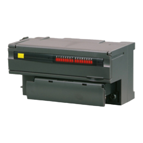
The DIN 18040 display module adds the
functions of visual displays for "Speak" and
"Open door" to the Gira door
communication system 106. The display
module meets the criteria for "barrier-free
construction" according to DIN 18040.
Scope of supply
1 x System 106 display module
1 x operating instructions
Check that the package contents are
complete and undamaged. When filing
complaints, see "Warranty".
Necessary accessories
• System 106 intercom module (Item no.
5563 ..) with call-button module (555. ..)
or door station module (Item no.
5565 9..).
• Audio control device (item no. 1287 00).
• Gira home station.
• System 106 surface-mounted housing,
1-gang to 5-gang (Item no. 5501 ...,
5502 ..., 5503 ..., 5504 ..., 5505 ...).
Device description
Front view
Electrical devices may only be
installed and connected by a
qualified electrician!
1 Glass front
2 Display: Voice connection active
3 Display: Door opener active
1
2
3
Rear view
Installing the module
Display symbols
Voice communication active
The symbol lights up when voice
communication is activated.
Door opener active
The symbol lights up when the door opener
is activated.
Starting up the module
The display module can only be started up
via the control device when connected to a
1 Turn-type lock (4 x)
2 Slot (2 x): System cable
3 Glass front mounting (4 x)
Installing the module
The installation instructions for the
System 106 surface-mounted 1-gang to 5-
gang housing describes the following
working steps:
• Lock the module on the mounting
frame.
• Plug in the connection cable.
• Place terminating resistors.
Terminating resistor
From the 2-gang surface-mounted housing
up, there are always two terminating
resistors included.
The terminating resistors are always
connected to the first and last module on
the system cable.
Delayed display "door opener ac-
tive"
After a call button has been taught in and
the display module is connected to the
System 106 door station, the display
signals "door opener active" in sync with
the activated door opener.
Changing the door opener interval via the
control device leads to display delays on
the module. Therefore, after changing the
door opener interval, the programming
mode must be activated and then
immediately deactivated again on the
control device for the display module to
adopt the new door opener interval.
Brightness of the display symbols
When active, the brightness of the display
symbols is automatically adjusted via the
door station or intercom module
depending on the ambient brightness.
2
1
3
intercom and call-button module or a door
station module (see installation and
operating instructions of the control device).
For a successful start-up, all components
(System 106 modules, home stations, audio
or video control device, etc.) must have
been previously installed.
Changing the glass front
1. Open the housing and remove the
mounting frame.
2. Unlock the display module and remove it
from the mounting frame.
3. Remove mounting screws and then
remove the glass front including seals.
4. Position new glass front with a new seal
and assemble in reverse order.
Technical data
Warranty
The warranty is provided in accordance with
statutory requirements via the retailer.
Please submit or send faulty devices
postage paid and with an error description
to your sales representative (retailer/
installation company).
The salesperson will forward the devices to
the Gira Service Center.
1 Glass front
2 Seal
3 System 106 DIN 18040 display module
4 Mounting screws (4 x)
Power
supply: Via system (flat
ribbon cable, 10-pin)
Power consumption
Per lit symbol:
250 mW
Stand-by mode: 14 mW
Connections: 2 x system
Ambient
temperature: -25 °C to +70 °C
Protection IP54
Dimensions (W x H): 106.5 x 106.5 mm
1 32 4
10864531 40/16
System 106
DIN 18040 display
module
5567 000
Operating instructions
en
55671110_Anzeigenmodul_en.fm Seite 1 Freitag, 11. November 2016 11:47 11
