Gira 1345 26 User manual

Installation/Mounting Instructions
Energy profile with three empty units,
height: 491 mm
1345 26/28
Energy profile with lighting element and three empty units,
height: 769 mm
1349 26/28
Energy profile with six empty units,
height: 769 mm
1351 26/28
2
Table of contents
Device description ............................................ 2
Device presentation .......................................... 2
Setting up energy profile .................................. 3
Outfitting available device units........................ 4
Connecting up energy profile ........................... 5
Installing/replacing light.................................... 5
Inserting slats ................................................... 6
Technical data................................................... 6
Warranty........................................................... 7
Device description
Energy profile for outdoors, made of powder-
coated aluminium.
The available empty units can be outfitted as
desired with all the functions from the TX_44 and
System 55 switch design ranges, e.g. an
automatic switch, a telephone jack or a
loudspeaker connection.
The lighting element provides area and guiding
illumination, e.g. in an entrance area.
The Gira energy profile is available in different
versions in the colours anthracite and aluminium.
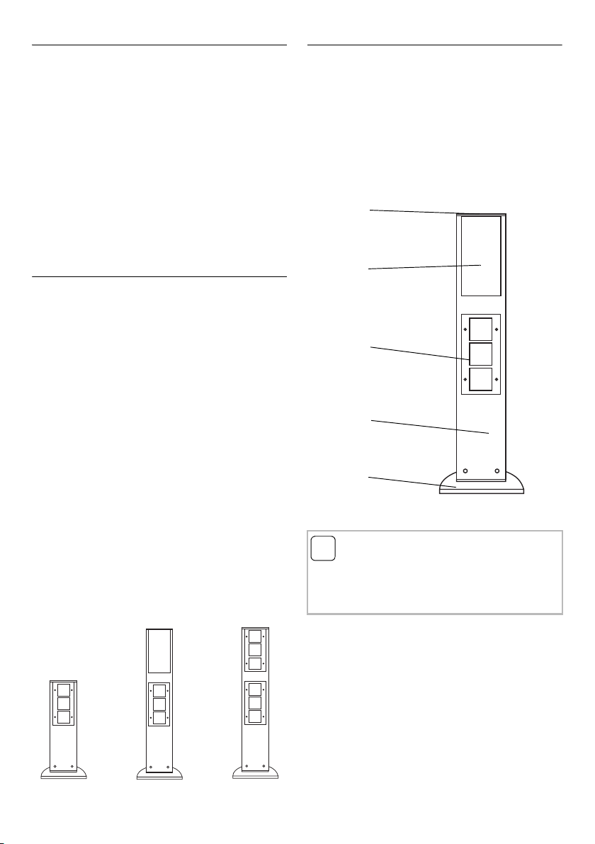
Examples:
• Energy profile with three empty units,
height: 491 mm
Order No. 1345 26/28
• Energy profile with lighting element and three
empty units, height 769 mm
Order No. 1349 26/28
• Energy profile with six empty units,
height: 769 mm
Order No. 1351 26/28
Device presentation
Here, the energy profile with a lighting element is
used as an example for presentation of the basic
energy profile design:
(1) Cover
(2) Lighting element with diffusing plate
(3) Available device unit with TX_44 frame
(4) Aluminium profile
(5) Aluminium profile base
i
Notes on care
Please use only soap suds or a solvent-free, non-
abrasive cleaning agent to clean the energy
profile.
1
2
3
4
5

3
Setting up energy profile
Condensation water opening
Before mounting the energy profile, open the
condensation water drain on the bottom of the
profile base. For this purpose, knock out the
opening (see arrow) and remove the burr with a
file.
The energy profile is fastened with only one bolt.
Depending on the conditions of the foundation,
there are two options for anchoring the energy
profile to the ground.
With an underground tube
The energy profile is set up using the
underground tube on loose or soft ground, e.g. in
flowerbeds or on grass.
1. Dig a hole approx. 50 cm deep at the
intended mounting site.
2. Guide the cables through the underground
tube and cement the tube in vertically and
flush with the surface.
3. Guide the cables through the profile base.
4. Mount the profile base to the underground
tube with the accompanying hexagon bolt.
5. Guide the cables into the accompanying
conduit boxes and connect the plastic-
sheathed cables which reach the device
units.
6. Connect the lighting element (if present)
(see Page 5).
7. Connect the earth cable of the energy profile
to the earth terminal of the profile base.
8. Place the energy profile on the profile base
and fasten it with the three Allen bolts
(M6 x 14).
9. For energy profiles with a lighting element,
insert the light and close the profile with the
cover.
Attention
The installation and assembly of electrical
equipment may only be performed by a qualified
electrician.
Position of the underground tube
Note the position of the energy column when
cementing in the underground tube It can be
aligned by max. 20° on the underground tube.
i
Profile with no lighting element
For profiles with no lighting element, all devices
and TX_44 cover frames must be mounted
before the profile cover is set in place. To keep
the profile splash-resistant, the top edge of the
TX_44 cover frame must be flush with the top
edge of the profile.

4
Screwing down directly
The energy profile can be set up directly on the
ground on a solid base, e.g. a cement or asphalt
surface.
.
1. Drill a hole at the intended mounting location
and insert the accompanying plug.
2. Guide the cables through the profile base and
mount the base to the ground with the
accompanying hexagon bolt.
3. Guide the cables into the accompanying
conduit boxes and connect the plastic-
sheathed cables which reach the device
units.
4. Connect the lighting element (if present) (see
Page 5).
5. Connect the earth cable of the energy profile
to the earth terminal of the profile base.
6. Place the energy profile on the profile base
and fasten it with the three Allen bolts
(M6 x 14).
7. For energy profiles with a lighting element,
insert the light and close the profile with the
cover.
Outfitting available device units
The empty units of the energy profiles can be
outfitted with components from the TX_44 or
System 55 switch design ranges.
Please install the flush-mounted inserts as
follows:
1. Connect the device inserts.
2. Lay the connection lines in the conduit boxes.
3. Fit the inserts with the accompanying sealing
pans. The profile has markings to which the
supporting rings of the device can be aligned.
This ensures that the frames are inserted later
on in such a way which ensures splash
resistance.
4. Set down the bottom section of the TX_44
frame and fasten it with the accompanying
Phillips-head screws (B 3.5 x 16).
5. Fit the central inserts and screw them down if
necessary.
6. Attach the adapter plates with a hinged cover
if necessary.
7. Clip on the cover plate of the frame and press
in the Torx screws.
i
Profile with no lighting element
For profiles with no lighting element, all devices
and TX_44 cover frames must be mounted
before the profile cover is set in place. To keep
the profile splash-resistant, the top edge of the
TX_44 cover frame must be flush with the top
edge of the profile.
i
Installation suggestion
Prepare the energy profile in your workshop:
Install the devices and lay the corresponding
plastic-sheathed cables in the conduit boxes.
Then only the conduit boxes need be wired up
on site.
i
Integration of System 55 inserts
Inserts from System 55 must be installed via a
TX_44 adapter plate with a hinged cover. An
overview of the inserts which can be combined
with each adapter plate is found in the current
Gira catalogue.
5
Connecting up energy profile
Earth connection
Energy profiles with lighting elements and
energy profiles which contain devices powered
by 230 V must be earthed. The energy profiles
have the following earth terminals:
• The lighting element is earthed via the terminal
in the conduit box. The lighting element is also
connected to the profile.
• An earth cable extends down to the profile
base. Connect this cable to the profile base.
• If devices powered by 230 V are inserted into
the empty units, the power profile must also be
earthed. An additional earth terminal is
available for this near the device unit. Connect
this to the earth cable of the 230 V device.
Device connection
Due to the variability of the energy profile, all
flush-mounted devices from the TX_44 or
System 55 switch design range can be
integrated. For this reason, please refer to the
respective operating instructions accompanying
each device for information on how each device
is connected.
Lighting element connection
The lighting element of the energy profile is
already pre-wired up to the connection terminal.
Proceed as follows to connect the lighting
element:
1. Remove the connection box from the lower
opening of the energy profile and open it.
2. Connect the lighting element via the /N/
terminals.
The available terminals can be used for the
wiring of the empty units.
3. Close the connection box and push it back
into the energy profile.
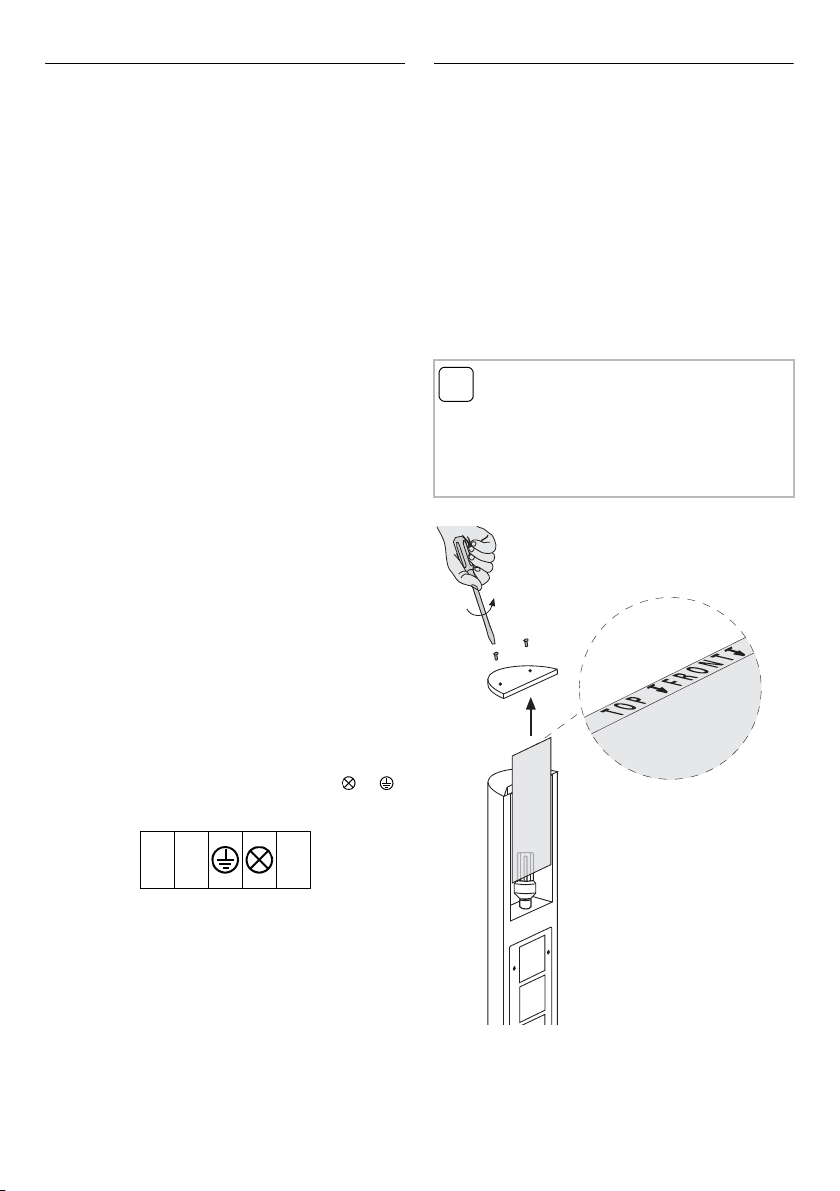
Installing/replacing light
Light sources with E27 treading of the energy
efficiency classes A++ to E can be used.
To install or replace the light, proceed as follows:
1. Loosen both cover screws and remove the
profile cover.
2. Pull the diffusing plate upward from the
guide.
3. Insert the light.
4. Reinsert the diffusing plate from above
(please note the "TOP FRONT" labelling).
5. Set the profile cover in place and fasten it
with both cover screws.
LN
i
Light diameter
Lamps with a base diameter of up to 52 mm can
be used in the Energy Profile.
If a slats element is used, the maximum base
diameter is reduced to 48 mm!

6
Inserting slats
Using the optionally available slats, the lighting
element of the energy profile can be used for
targeted object or path illumination.
To use the slat element and the accompanying
transparent plate, proceed as follows:
1. Loosen both cover screws and remove the
profile cover.
2. Pull the diffusing plate upward from the
guide.
3. Insert the transparent plate from above
(please note the "TOP FRONT" labelling).
4. Insert the slat element:
Slats directed upward,
e.g. for object illumination.
Slats directed downward,
e.g. for path illumination.
5. Set the profile cover in place and fasten it
with both cover screws.
Technical data
Dimensions (W x H x D)
Profile base: 229 x 10 x 155 mm
Profile: 142 x 491 x 75 mm or
142 x 769 x 75 mm
Protection type: IP 44 with closed
device covers
Connections: terminal screws 1 x 4 mm2
or 2 x 2.5 mm2
Lamp: Light sources with E27
treading of the energy
efficiency classes A++ to E
Power: 21 W max.
Diameter: 52 mm max.
48 mm max.
(if slats element is used)
Lit area
Energy profile with lighting element, height
769 mm, frosted diffusing plate, 20 W
Hight of point of light above ground: 0,65 m
i
Transparent plate/diffusing plate
The slat element can be used with either the
transparent plate or the frosted diffusing plate.

7
Warranty
The warranty is provided in accordance with
statutory requirements via the specialist trade.
Please submit or send faulty devices postage
paid together with an error description to your
responsible salesperson (specialist trade/
installation company/electrical specialist trade).
They will forward the devices to the
Gira Service Center.

Gira
Giersiepen GmbH & Co. KG
Electrical installation
systems
Industriegebiet Mermbach
Dahlienstraße
42477 Radevormwald
P.O. Box 12 20
42461 Radevormwald
Germany
Phone+49 (0) 2195 602 - 0
Fax +49 (0) 2195 602 - 191
www.gira.com
info@gira.com
10866543 49/19
This manual suits for next models
5
Table of contents
Other Gira Control Unit manuals

Gira
Gira System 3000 User manual

Gira
Gira LEDOTRON User manual

Gira
Gira 0644 Series User manual

Gira
Gira 1019 00 User manual

Gira
Gira 5567 000 User manual

Gira
Gira System 106 Fingerprint Module 5551 User manual

Gira
Gira 1283 00 User manual

Gira
Gira System 3000 User manual

Gira
Gira DALI 5422 00 User manual

Gira
Gira eNet User manual


