GME TX3120SPNP User manual

Super compact 5 watt UHF CB radio
ScanSuite
™
5 YEAR WARRANTY
INSTRUCTION MANUAL

PAGE 2 INSTRUCTION MANUAL TX3120S
SUPPLIED WITH
TX3120S Radio DC Lead
Mounting Cradle Screw pack and Adaptor
Microphone Instruction Manual
Microphone clip
CONTENTS
SUPPLIED WITH...................................................2
INTRODUCTION ..................................................3
IMPORTANT INFORMATION CONCERNING UHF
CB RADIO ...........................................................3
POSSIBLE ISSUES.................................................3
EMERGENCY CHANNELS ....................................4
TELEMETRY CHANNELS.......................................4
SAFETY MOUNTING GUIDELINES - P’N’P.............4
FEATURES...........................................................5
GENERAL OPERATION.........................................7
Front Panel Controls............................................7
Rear Panel ..........................................................7
LCD Panel...........................................................8
Microphone ........................................................8
ON/OFF Switch....................................................9
Volume...............................................................9
Minimum Volume Setting (VMIN) ........................9
Receive Audio Mute ............................................9
Selecting Channels..............................................9
Configuration Menu ..........................................10
Flipping the Display...........................................12
Squelch.............................................................12
Signal Meter .....................................................13
Transmitting......................................................13
Time-out Timer..................................................13
Backlighting......................................................13
Dynamic Volume Control (DVC) .........................15
Voice Scrambler ................................................15
Beep Tone Volume ............................................16
Silent Squelch Tail .............................................16
Disabling the Internal Speaker ...........................17
Repeaters and Duplex .......................................17
Priority Channel ................................................19
Scanning...........................................................19
OPEN SCAN......................................................20
Group Scan.......................................................22
Network Scan (Net-Scan)...................................23
CTCSS & DCS....................................................25
INSTALLATION ..................................................27
Fitting the Radio ...............................................28
Flipping the Display...........................................30
Antenna Connection .........................................30
Microphone Connection ....................................31
WIRING ............................................................31
DC Power Connection .......................................31
Noise Suppression.............................................32
High Voltage Detection .....................................32
CTCSS TONE FREQUENCY CHART .....................33
DSC CODE CHART.............................................34
UHF CB OPERATING FREQUENCIES...................35
SPECIFICATIONS ...............................................36
SC WARRANTY AGAINST DEFECTS....................38

TX3120S INSTRUCTION MANUAL PAGE 3
INTRODUCTION
The TX3120S is Australian designed and
engineered combining the latest in electronic
hardware with up-to-date computer aided design
and manufacturing techniques to produce an
extremely compact mobile radio with outstanding
specifications and performance.
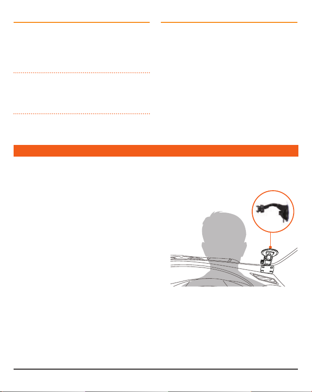
Your radio is designed for unobtrusive mounting
in modern vehicles. With its built-in loud speaker,
speaker microphone and extremely small size, it
can be mounted in almost any convenient location.
IMPORTANT INFORMATION
CONCERNING UHF CB RADIO
The use of the Citizen Band radio service is licensed
in Australia by the ACMA Radio communications
(Citizens Band Radio Stations) Class Licence and
in New Zealand by the Ministry of Economic
Development New Zealand (MED).
A General User Radio Licence for Citizens Band
radio and operation is subject to conditions
contained in those licences.
The class licence for users and equipment operating
in the CB/PRS 477 MHz band has been amended.
This radio meets the new 80 channel standard.
In simple terms the same amount of spectrum is
available; however, radio transceivers can now
operate in a narrower bandwidth and hence use
less spectrum. These radios are generally referred
to as narrowband or 12.5 kHz radios. By using
12.5 kHz channel spacing instead of 25 kHz,
the 40 channels originally allocated can now be
expanded to 80 channels thereby doubling the
channel capacity and relieving congestion in the
UHF CB/PRS band.
Original 40 channel wideband Radios will continue
to operate on the original 40 channels, however
they will not be able to converse on the newer
channels 41 – 80. The newer narrowband radios
will be able to converse with all older 40 channel
wideband radios on all channels 1 to 40 as well as
the newer channels allocated from 41 to 80.
The mixing of narrowband and wideband radios
in the same spectrum can cause some possible
operating issues of interference and varying levels
of received volume.
POSSIBLE ISSUES
When a new narrowband radio receives a
transmission from an older wideband radio the
speech may sound loud and distorted – simply
adjust your radio volume for best performance.
When an older wideband radio receives a signal
from a new narrowband radio, the speech may
sound quiet – simply adjust your radio volume for
best performance.
Depending on how close your receiving radio
is to another transmitting radio, there can be
interference from the transmitting radio if it is
using a channel adjacent to the channel you are
listening to. Simply try going up or down a few
channels from the currently selected channel.
The above situations are not a fault of the radio
but a symptom of operating wideband and
narrowband radios in the same bandwidth. This
possible interference will decrease over time as the
population of wideband radios ages and decreases.
Further information and updates are available
from the Australian Communications and Media
Authority (ACMA) at www.acma.gov.au and the
Ministry of Economic Development (MED), Radio
Spectrum Management at: www.rsm.govt.nz

PAGE 4 INSTRUCTION MANUAL TX3120S
EMERGENCY CHANNELS
The ACMA has allocated channels 5/35 for
emergency use only. Channel 5 is the primary
Simplex Emergency Channel. Where a Channel 5
repeater is available, you should select Duplex on
CH 5.
NOTE: Channel 35 is the input channel for
the Channel 5 repeater therefore Channel 35
should also not be used for anything other than
emergency transmissions.
TELEMETRY CHANNELS
ACMA regulations have allocated channels 22
and 23 for telemetry only applications and have
prohibited the transmission of speech on these
channels. Consequently your radio has a transmit
inhibit applied to channels 22 and 23.
In the event additional telemetry/telecommand
channels are approved by the ACMA, these
channels shall be added to those currently listed
where voice transmission is inhibited. Currently
transmissions on channels 61, 62 and 63 are also
inhibited and these channels are reserved for future
allocation.
SAFETY MOUNTING GUIDELINES FOR PLUG ‘N’ PLAY
The TX3120S Plug ‘n’ Play (TX3120SPNP) is
supplied with a suction mount bracket - Part No:
MB043, designed to hold the TX3120S UHF CB
radio so that it can be remotely mounted onto the
windscreen within the vehicle or alternatively on a
flat surface where the suction base can take hold.
In order to ensure driver safety when using the
TX3120S Plug ‘n’ Play, GME provides the following
recommendations and guidelines;
• The product should not be mounted in a way
that blocks the driver’s field of vision of the
road.
• When mounting on the driver’s side of the front
windscreen, it is recommended the suction be
placed as close as possible to the corner of
the windscreen to minimise interruption to the
driver’s field of vision.
• If fitted elsewhere on the windscreen it should
be low down to ensure the driver’s field of
vision is not blocked.
•If it is not possible or practical due to the design
of the dash or the driver’s seating position, the
unit may be placed low down in the centre of
the windscreen.
• The unit must not be located in a position
that could potentially cause injury during a
crash – such as a head strike to the unit. Airbag
deployment should also be considered when
mounting the unit.
• Mounting the unit high up on any part of the
windscreen is not recommended as it may cause
an interruption to the driver’s field of vision or

TX3120S INSTRUCTION MANUAL PAGE 5
FEATURES
TRANSMIT (TX)
Individually Programmable DUPLEX Function: User selectable for only those individual channels
in your area that have repeaters, leaving the others free for use as extra simplex channels.
RECEIVE (RX)
Silent Squelch Tail:Eliminates the Squelch noise burst normally audible when the Squelch closes
Signal Receive Indicator: Confirms that an incoming signal is being received
SCANNING AND MEMORY FUNCTIONS
Microprocessor Controlled Frequency Synthesiser: Allows user programmable control of
scanning, channel memories and selected feature options.
Programmable Scan Function
:Scans the selected UHF CB channels with Group, Open and Network
scan functions available.
Priority Channel: A user programmable Priority channel feature allows your working channel to be
instantly recalled at the press of a key
SIGNAL PROCESSING
Digital Signal Processing: Measures filters and compresses standard analogue audio signals and
converts them into digital format. Allows advanced RF and audio processing techniques to be applied
to maximise the radio’s performance.
Advanced Signal Management: Identifies interference caused by strong local signals on adjacent
channels and prevents these from opening your Squelch. ASM also minimises distortion on reception by
fine tuning the receiver frequency to match that of the incoming signal.
Dynamic Volume Control: Automatically compensates for variations in received audio level to
provide a constant audio output level to the speaker.
interfere with rear view mirrors and sun visors.
It may also result in the DC power lead trailing
in the field of vision.
• Deciding on the location of the unit should also
factor where power leads may need to run to
avoid the possibility of them interfering with or
becoming entangled in vehicle controls.
• Covering or restricting access to dash
instruments and controls is not recommended.
The responsibility of deciding the location of where
the unit is mounted rests entirely with the end-user
and should be carefully considered to ensure
compliance with any state or federal laws.

PAGE 6 INSTRUCTION MANUAL TX3120S
PRIVACY FUNCTIONS
Voice Inversion Scrambler: When activated, scrambles your voice so that communications are only
intelligible to others using the same scrambler technology.
Inbuilt CTCSS & DCS: User selectable Continuous Tone Coded Squelch System and Digital Coded
Squelch system provides silent operation on individual channels.
PHYSICAL PROPERTIES
Over Voltage Protection: Special overvoltage detection circuitry protects the radio and warns of
excessive voltage conditions by flashing the display.
Rugged Construction: With die-cast chassis
Speaker Microphone: Improves receiver audio clarity in noisy environments by bringing the sound
closer to you.
USER CONTROLS AND INTERFACE
Full Spectrum Backlighting: User adjustable, totally customisable backlight settings to match the
vehicle’s dashboard lighting or driver’s preference.
Flip Feature: Unit can be mounted with the speaker facing upwards or downwards and the display
‘flipped over’ using a simple menu selection to allow viewing of the display from either mounting
orientation. Keys use symbols to provide readability in all installations.
High Contrast Liquid Crystal Display: Fully detailed LCD provides a visual indication of the selected
channel and all selected functions at a glance.
Rear Microphone Input: Facilitates ease of installation and operation across a wider range of
vehicles.
Digital Signal Strength Meter: Provides a numeric signal strength indication in numbers from
0 to 9+

TX3120S INSTRUCTION MANUAL PAGE 7
REAR PANEL
FRONT PANEL CONTROLS
GENERAL OPERATION
Volume Control
On/Off
LCDChannel Control
Squelch
Scan
DC Socket
Speaker
Antenna
Microphone

PAGE 8 INSTRUCTION MANUAL TX3120S
MICROPHONE
LCD PANEL
Channel DownChannel Up
Push To Talk
Scan
Priority Channel
Priority
Busy
Transmit
DuplexScan
Channel
Information
CTCSS/DCS
Signal
Meter

TX3120S INSTRUCTION MANUAL PAGE 9
ON/OFF SWITCH
Press the Volume control to turn the radio on. Press
and hold the Volume control to turn the radio off.
VOLUME
Rotate the Volume control left or right to adjust
the volume. During volume adjustment the
Volume level is displayed on the LCD as ‘VOL01’
(minimum) to ‘VOL31’ (maximum).
MINIMUM VOLUME SETTING (VMIN)
By default, when the Volume control is set to
minimum (VOL01) there is still a sufficient level
of residual audio from an incoming signal to be
heard in a quiet cabin environment. If required, the
minimum volume level can be adjusted through the
‘VMIN’ option in the Menu.
To adjust the minimum volume level
1. Press and hold the Channel control to enter
the menu. The display will show the current
Squelch level setting.
2. Rotate the Channel control until ‘VMINx’ is
displayed (where ‘x’ is a value from 1 – 9),
then press the Channel control to select it. The
VMIN value will be flashing.
3. Rotate the Channel control to make the
desired selection from 1 – 9. For the lowest
minimum volume level select 1.
When finished briefly press the Channel Control
to return to the menu or press and hold the
Channel Control to exit the menu.
RECEIVE AUDIO MUTE
There may be times when it is desirable to
temporarily override the minimum volume setting
and completely mute the receiver audio.
To mute the receiver audio, briefly press the
Volume control. ‘MUTE’ will flash on the display
and the receiver audio will be muted. During this
time you may see the icon appear but no sound
will be heard in the speaker.
To unmute the receiver audio, briefly press (or
rotate) the Volume control again. ‘MUTE’ will be
removed from the display and the receiver audio
will be restored to its previous volume setting.
SELECTING CHANNELS
To select the required channel, rotate the
Channel control (or press the or keys on
the microphone). Rotate the Channel control
clockwise (or press the key ) to select a higher
channel or counter clockwise (or press the key)
to select lower channels. The selected channel is
displayed on the LCD.

PAGE 10 I NSTRUCTION MANUAL TX3120S
CONFIGURATION MENU
The configuration menu provides access to all the
radio’s preset settings.
To use the menu
1. Press and hold the Channel control until a
beep is heard. The radio will enter the menu
and the first menu item (Squelch level) will be
displayed.
2. Rotate the Channel Control left or right to
select the required menu item then press the
Channel control to edit it. The selected item
will flash.
3. Rotate the Channel control to adjust the
selected item.
a. To save the current setting and return to the
menu, briefly press the Channel control.
b. To exit without saving and return to the
menu, briefly press the Volume control.
c. To save the current setting, exit the menu and
return to normal operation, press and hold
the Channel control or simply wait a few
seconds for the menu to time-out.
The following Menu items (page 10) are available:
SQL
WHITE
COLOR
BKLGT
FLIP
SST
BCL
VMIN
S-MET
DVC
CTCSS
NETSCAN
SCAN
PRIORITY
DUP
SPK
BEEP
ENC
Volume Control
On/Off
Channel Control
Selected Menu Item

TX3120S INSTRUCTION MANUAL PAGE 11
DESCRIPTION DISPLAYED OPTIONS
Squelch Level SQL-1-> SQL-9
CTCSS/DCS Tones CTCOF (CTCSS/DCS Off)
CTC01 -> CTC50 (CTCSS Tones)
DT001 -> DT104 (DCS Codes)
Network Scan NS-OF (Off)
NS-01 -> NS-50 (Using CTCSS)
NS001 -> NS104 (Using DCS)
Scan Group OPEN (Open Scan)
GROUP (Group Scan)
NETWK (Network Scan)
Priority Channel PRI01 -> PRI80
Duplex DUPOF (Duplex Off)
DUPON (Duplex On)
Speaker (Internal) SPKOF (Off)
SPKON (On)
Beep Level BEEP0-> BEEP9
Scrambler Encoder ENCOF (Off)
ENCON (On)
Dynamic Volume Control DVCOF (Off)
DVCON (On)
S-Meter S-MET (Normal Signal Meter)
S-LIN (Linear Signal Meter)
BATT (Battery Voltage)
VMIN (Minimum Volume Preset) VMIN1-> VMIN9
Busy Channel Lockout BCLOF (Off)
BCLON (On)
Silent Squelch tail SSTOF (Off)
SSTON (On)
Flip the Display FLIP
Backlight Brightness BKLGT
Backlight Colour COLOR
Backlight Saturation WHITE

PAGE 12 I NSTRUCTION MANUAL TX3120S
FLIPPING THE DISPLAY
The TX3120S’s small size allows it to be mounted
in almost any convenient location. However the
most suitable location may sometimes require the
unit to be installed upside-down when referenced
to your driving position.
The TX3120S is designed to overcome this
situation by allowing the display to be ‘flipped’ so
that it can be read in either orientation. In addition
the keys have symbols that can also be read in
either orientation.
To flip the display
1. Press and hold the Channel control to enter
the menu. The display will show the present
Squelch level.
2. Rotate the Channel control until ‘FLIP’ is
displayed then briefly press the Channel
control to select it. ‘FLIP’ will flash.
3. Rotate the Channel control left or right to
flip the display. When the display is correctly
orientated, press and hold the Channel
control to exit the menu and return to normal
operation.
Front Panel Upright (Speaker Above)
Front Panel Fipped (Speaker Below)
SQUELCH
The Squelch is used to eliminate any annoying
background noise when there are no signals
present. The Squelch can be opened or closed by
pressing the key. When the Squelch is open
the receiver’s background noise can be heard and
the icon is displayed on the LCD. When the
Squelch is closed the receiver remains quiet while
there are no signals present but any incoming
signals will override the Squelch and be heard in
the speaker.
Adjusting the Squelch level
The Squelch sensitivity level has been factory set
to provide optimum performance under most
operating conditions. If required, the sensitivity
level can be adjusted via the menu to suit changing
conditions.
To adjust the Squelch sensitivity,
1. Press and hold the Channel control to enter
the menu. The display will show the current
Squelch level setting in values from SQL-1 to
SQL-9.
2. Briefly press the Channel control. The Squelch
level will flash.
3. Rotate the Channel control to change the
Squelch setting. A Squelch setting of SQL-1
allows the Squelch to open on very weak
signals whereas a setting of SQL-9 requires
much stronger signals to overcome the Squelch.
When finished briefly press the Channel control to
return to the menu or press and hold the Channel
control to exit the menu.

TX3120S INSTRUCTION MANUAL PAGE 13
NOTE: The Squelch level can be actively adjusted
while the radio is scanning. This allows you to
tighten the Squelch in cases where an undesired
weak or noisy signal is interrupting the scan.
SIGNAL METER
The signal meter indicates the relative strength of
the incoming signal in numerical format. A digital
signal strength level is displayed on the lower
left of the Channel Display in values from 0 to 9.
Signals above strength 9 are displayed as 9+.
The signal strength is also displayed on a bar graph
in the upper left of the display with a longer bar
indicating a stronger signal.
By default the digital signal strength meter displays
signal strengths in the standard logarithmic format
however it can be set to display signal strengths in
linear format or the location can be used to display
the battery voltage instead.
To change the digital signal strength options;
1. Press and hold the Channel control to enter
the menu. The display will show the current
Squelch level setting.
2. Rotate the Channel control until ‘S-MET’,
‘S-LIN’ or ‘BATT’ is displayed then press the
Channel control to select it. The selected
option will be flashing.
3. Rotate the Channel control to make the
desired selection.
• Select ‘S-MET’ to display the logarithmic signal
meter.
• Select ‘S-LIN’ to display the linear signal meter.
• Select ‘BATT’ to display the battery voltage
instead of signal strength.
When finished briefly press the Channel control to
return to the menu or press and hold the Channel
control to exit the menu.
TRANSMITTING
Prior to transmitting, always check the channel
is not being used. This can be done by listening
to the channel or by visually checking that the
icon is not visible or the signal meter is not
indicating a signal.
To transmit, press the PTT on the microphone. The
icon will appear. Hold the microphone about
5-8 cm from your face and speak at a normal voice
level. The microphone is quite sensitive so it is not
necessary to raise your voice or shout. Release the
PTT when you have finished talking. The icon
will disappear.
IMPORTANT:Always listen to ensure the channel
is free before transmitting.
TIME-OUT TIMER
The radio has a built-in time-out timer that
automatically limits transmissions to a maximum
of 3 minutes of continuous operation. This feature
is required by the ACMA to prevent accidental
blocking of the frequency should your PTT become
jammed or be otherwise pressed accidentally.
Ten seconds before time-out occurs, ‘TOT’ will
flash on the display. Once time-out has occurred an
alert beep will be heard and the radio will return
to receive mode. If the PTT remains pressed, ‘TOT’
will continue flashing on the display until the PTT
is released. Normal operation will then be restored.
BACKLIGHTING
The Liquid Crystal Display and keys are backlit for
easier viewing at night. The backlight remains on
whenever the radio is switched on.

PAGE 14 I NSTRUCTION MANUAL TX3120S
Adjusting the Backlighting
The backlight brightness and colour can be
adjusted via the menu for personal preference.
There are three backlight settings available.
BKLGT (Brightness setting): Provides a
continuously variable brightness adjustment from
very dim to full brightness.
COLOR (Colour setting): Provides a continuously
variable adjustment through the full colour
spectrum.
White (Whiteness setting): Controls the colour
saturation of the selected colour from deep colour
to white (no colour).
To adjust the backlighting;
Press and hold the Channel control to enter the
menu. The display will show the current Squelch
level setting.
Brightness
1. Rotate the Channel control left or right until
‘BKLGT’ is displayed then briefly press the
Channel control to select it. ‘BKLGT’ will flash.
2. Rotate the Channel control left or right to
adjust the display brightness. Rotate right to
increase the brightness or left to decrease the
brightness.
3. Briefly press the Channel control to return to
the menu.
Colour
1. Rotate the Channel control to the right until
‘COLOR’ is displayed then briefly press the
Channel control to select it. ‘COLOR’ will flash.
2. Rotate the Channel control left or right to
adjust the colour.
3. Briefly press the Channel control to return to
the menu.
Whiteness
1. Rotate the Channel control to the right until
‘WHITE’ is displayed then briefly press the
Channel control to select it. ‘WHITE’ will flash.
2. Rotate the Channel control left or right to
adjust the colour saturation (whiteness). Rotate
right to reduce the colour intensity or left to
increase it.
3. Briefly press the Channel control to return
to the menu or press and hold the Channel
control to exit the menu and return to normal
operation.
Auto-colour Mode
The radio has an automatic colour-change option
that, when activated, will cause the display colour
to automatically cycle through the available
colour spectrum. The colour-change option can be
enabled temporarily as an aid to choosing a display
colour or can be set to cycle continuously as the
preferred display colour setting.
To enable the auto-colour option,
1. Press and hold the Channel control to enter
the menu. The display will show the current
Squelch level setting.
2. Rotate the Channel control left or right until
‘COLOR’ is displayed.
3. While ‘COLOR’ is displayed, briefly press the
key to enable or disable the auto-colour
option. When enabled, the display lighting will
continuously cycle through the available colour
spectrum. When disabled the display will hold
the last selected colour.

TX3120S INSTRUCTION MANUAL PAGE 15
When finished briefly press the Channel control to
return to the menu or press and hold the Channel
control to exit the menu. If auto-colour is still
enabled, the display lighting will continue to cycle
through the colour spectrum until disabled using
the steps above.
DYNAMIC VOLUME CONTROL (DVC)
The modulation level of signals heard on the
UHF CB band can vary considerably resulting in
noticeable differences in received audio volume.
Often users compensate for this by adjusting
the Volume control for each incoming signal.
With the introduction of 80 channel narrowband
transmissions using lower levels of modulation, the
diversity in received audio volume has increased
further. Your TX3120S is fitted with a Dynamic
Volume Control feature which, when activated,
automatically compensates for these variations in
audio level resulting in a constant audio output
level to the speaker.
To activate the Dynamic Volume Control
1. Press and hold the Channel control to enter the
menu. The display will show the current Squelch
level setting.
2. Rotate the Channel control until ‘DVCOF’ or
‘DVCON’ is displayed then press the Channel
control to select it. ‘ON’ or ‘OF’ will be flashing.
3. Rotate the Channel control to make the
desired selection. Select ‘DVCON’ to switch the
Dynamic Volume Control ON or ‘DVCOF’ to
switch it OFF.
When finished briefly press the Channel control to
return to the menu or press and hold the Channel
control to exit the menu.
Dynamic Volume Control ON
Dynamic Volume Control OFF
VOICE SCRAMBLER
Your radio incorporates a simple voice scrambler
using band inversion. The scrambler is compatible
with the majority of scramblers used by other
manufacturers, allowing you to enjoy scrambled
communications with owners of non-GME radios.
Once the scrambler has been activated your
transmission and reception will only be intelligible
to others using the same scrambler technology.
To enable or disable the voice scrambler
1. Press and hold the Channel control to enter the
menu. The display will show the current Squelch
level setting.
2. Rotate the Channel control until ‘ENCOF’ or
‘ENCON’ is displayed then press the Channel
control to select it. ‘ON’ or ‘OF’ will be flashing.
3. Rotate the Channel control to the right to
enable the scrambler encoder. ‘ENCON’ will be
displayed.
4. Rotate the Channel control to the left to
disable the Scrambler encoder. ‘ENCOF’ will be
displayed.
When finished briefly press the Channel control to
return to the menu or press and hold the Channel
control to exit the menu.

PAGE 16 I NSTRUCTION MANUAL TX3120S
Scrambler Encoder ON
Scrambler Encoder OFF
BEEP TONE VOLUME
The Beep Tone provides audible feedback
whenever the keys are pressed. You can adjust the
volume of the key beeps as follows.
1. Press and hold the Channel control to enter
the menu. The display will show the current
Squelch level setting.
2. Rotate the Channel control until ‘BEEPx’ is
displayed (where x is a beep volume level from
0 – 9) then press the Channel control to select
it. The beep volume level will be flashing
3. Rotate the Channel control to adjust the Beep
volume from 0 – 9. To switch the Beep Tone
OFF select 0.
When finished briefly press the Channel control to
return to the menu or press and hold the Channel
control to exit the menu.
Beep level = 2
SILENT SQUELCH TAIL
The Squelch tail is the short burst of noise that is
heard in the speaker at the end of a transmission
just before the Squelch closes. To some it is a
reassuring confirmation that it is their turn to
transmit but in some applications it may be an
annoyance especially when listening through an
earpiece or headphones.
The Silent Squelch Tail function removes this noise,
reducing it to a faint click as the Squelch closes.
To enable or disable the Silent Squelch Tail
1. Press and hold the Channel control to enter
the menu. The display will show the current
Squelch level setting.
2. Rotate the Channel control until ‘SSTxx’ is
displayed (where xx = ON or OF), then press
the Channel control to select it. ‘ON’ or ‘OF’
will be flashing.
3. Rotate the Channel control to the right to
enable the Silent Squelch Tail. ‘SSTON’ will be
displayed and the Squelch Tail will become silent.
4. Rotate the Channel control to the left to
disable the Silent Squelch Tail. ‘SSTOF’ will be
displayed and the Squelch Tail will be restored.
When finished briefly press the Channel control to
return to the menu or press and hold the Channel
control to exit the menu.
Silent Squelch Tail On
Silent Squelch Tail OFF

TX3120S INSTRUCTION MANUAL PAGE 17
DISABLING THE INTERNAL SPEAKER
The TX3120S has two speakers – one mounted
inside the radio and the other mounted inside the
microphone. By default, sound is reproduced by
both speakers; however if you prefer, the radio’s
internal speaker can be switched off leaving just
the speaker/microphone to reproduce sound.
To switch off the radio’s internal speaker
1. Press and hold the Channel control to enter the
menu. The display will show the current Squelch
level setting.
2. Rotate the Channel control until ‘SPKxx’ is
displayed (where xx = ON or OF), then press
the Channel control to select it. ‘ON’ or ‘OF’
will be flashing.
3. Rotate the Channel control to the right to
switch the internal speaker ON. ‘SPKON’
will be displayed.
4. Rotate the Channel control to the left to
switch the internal speaker OFF. ‘SPKOF’
will be displayed.
When finished briefly press the Channel control
to return to the menu or press and hold the
Channel control to exit the menu.
REPEATERS AND DUPLEX
Duplex operation allows the radio to transmit on
a different frequency to that which it receives. This
allows operation through repeater stations.
A repeater station consists of a linked transmitter/
receiver combination installed in a prominent
location. The repeater is designed to receive signals
on a designated channel and retransmit them on
another channel. Repeaters are usually mounted on
hills or tall buildings. The increase elevation greatly
improves both the receiving and transmitting range
of the repeater allowing it to receive and retransmit
signals to radios that would otherwise be out of
range of each other.
Normally, UHF radios transmit and receive on the
same frequency – known as Simplex operation.
However to communicate through repeaters, your
radio must be able to transmit and receive on
different channels – otherwise known as Duplex
operation. Your radio has a Duplex function to
allow you to operate through repeaters.
The Duplex function can only be selected on
channels 1 – 8 and 41 – 48 as these are the
channels that have been allocated for repeater use.
When Duplex is selected, your radio receives on
the selected channel (e.g. CH 1) but transmits 30
channels higher (CH 31). The repeater hears your
signal on CH 31 and retransmits it on CH 1 for
others to hear.
CHANNEL 31
CHANNEL 1
CHANNEL 1
CHANNEL 31
VEHICLE
SIMPLEX
REPEATER
OPERATION
VEHICLE
REPEATER
STATION

PAGE 18 I NSTRUCTION MANUAL TX3120S
Your radio allows you to enable or disable Duplex
mode on individual repeater channels. In this way
any repeater channels that are not being used with
repeaters in your area can be used in Simplex mode
for normal direct radio-to-radio communications.
To enable or disable Duplex on a Repeater Channel
1. Select the required repeater channel (1 – 8,
41 – 48).
2. Press and hold the Channel control to enter the
menu. The display will show the current Squelch
level setting.
3. Rotate the Channel control until ‘DUPxx’ is
displayed (where xx = ON or OF), then press the
Channel control to select it.
NOTE: If ‘DUP- -‘ is displayed, the selected
channel is not a repeater channel. Please exit the
menu and select a repeater channel.
4. Rotate the Channel control to the right
to enable Duplex on the selected channel.
‘DUPON’ will be displayed and the icon
will appear.
5. Rotate the Channel control to the left to
disable Duplex on the selected channel.
‘DUPOF’ will be displayed and the icon
will disappear.
When finished press and hold the Channel
control to exit the menu.
Repeater channel not selected
Duplex On
Duplex Off
Channel
Selected
Receive
Channel
Transmit
Channel
1 1 31
2 2 32
3 3 33
4 4 34
5* 5* 35*
6 6 36
7 7 37
8 8 38
41 41 71
42 42 72
43 43 73
44 44 74
45 45 75
46 46 76
47 47 77
48 48 78
*Emergency channel only

TX3120S INSTRUCTION MANUAL PAGE 19
IMPORTANT: Channels 1 – 8, 31 – 38, 41 – 48
and 71 – 78 should only be used in Simplex mode
if there are no repeaters in or near your location
that operate on the selected channel. In particular,
avoid operating in Simplex mode on any of the
repeater input channels 31 – 38 and 71 – 78
unless you are absolutely sure that there are no
repeaters in range using that channel. Inadvertently
transmitting on an active repeater input frequency
in simplex mode could cause interference to other
users on that repeater that would not be audible
to your radio.
PRIORITY CHANNEL
The Priority channel feature allows you to instantly
recall any one of the 80 channels in your radio.
This feature can be used to provide instant access
to your working channel or your local repeater
channel at the press of key. It is also used in
conjunction with the Group Scan mode.
To store a Priority Channel;
1. Press and hold the Channel control to enter the
menu. The display will show the current Squelch
level setting.
2. Rotate the Channel control until ‘PRIxx’ is
displayed (where xx is a number from 01 - 80),
then press the Channel control to select it.
3. Rotate the Channel control to select your
required priority channel number.
When finished press and hold the Channel control
to exit the menu.
Priority channel = 80
To recall a Priority Channel;
Briefly press the Channel control. The radio will
immediately switch to the Priority channel. The
priority channel is identified by the * icon.
Priority
Channel
Icon
NOTE: If the radio was scanning when the Priority
channel was recalled, the scan will be cancelled.
SCANNING
Your radio incorporates a scan function allowing
selected groups of channels to be scanned for
signals. Channels can be scanned at a rate of
45 channels per second. When a signal is found,
scanning will pause to allow the signal to be heard
then resume scanning when the channel is clear
again.
Scan Groups
Your radio supports three scan groups - Open Scan,
Group Scan and Network Scan. Each scan group
has separate channel memories allowing you to
program your choice of channels into each group
for scanning.
Selecting a Scan Group
To select Open Scan, Group Scan or Network Scan;
1. Press and hold the Channel control to enter the
menu. The display will show the current Squelch
level setting.
2. Rotate the Channel control until ‘OPEN’,
‘GROUP’ or NETWK’ is displayed, then press the
Channel control to select it.

PAGE 20 I NSTRUCTION MANUAL TX3120S
3. Rotate the Channel control to select your
required Scan Group. Select ‘OPEN’ for Open
Scan, ‘GROUP’ for Group Scan or ‘NETWK’ for
Network Scan.
When finished press and hold the Channel control
to exit the menu.
Open Scan
Group Scan
Network Scan
NOTE: Network scan is disabled by default and
will not appear in the scan group list unless it has
been enabled. See Network Scan further below for
details on how to enable and use Network Scan.
Auto Skip
While scanning, if an active channel in your
scan group becomes a nuisance by constantly
interrupting the scan, briefly rotate the Channel
control (or press the or keys) while the radio
is paused on that channel. The busy channel will
be temporarily removed from the scan group to
allow time for the channel to become clear again
and scanning will continue from the next channel
in the sequence. After 30 seconds the skipped
channel will be reinstated in the scan sequence.
If the unwanted active channel continues to
interrupt the scan after the 30 second skip period
has elapsed, hold the key while the radio is
paused on that channel to completely remove that
channel from the scan group for the duration of
the scan session. To restore the channel, simply
stop and restart the scan session using the
key (or switch the radio Off then On again).
NOTE: You can skip as many busy channels
from the scan group as you wish, however if you
attempt to skip the last remaining channel, all the
previously skipped channels will be restored to the
scan group.
OPEN SCAN
Open Scan allows a group of channels to be
scanned in an ascending sequence. If a signal is
found, the scan will pause on that channel. During
this time you can press the PTT on the microphone
and talk on the channel. Once the channel has
been clear for 5 seconds the scan will resume.
e.g: Scanning channels 1 – 8 in Open Scan
1 - 2 - 3 - 4 - 5 - 6 - 7 - 8
Selecting Open Scan
To select Open Scan;
1. Press and hold the Channel control to enter
the menu. The display will show the current
Squelch level setting.
2. Rotate the Channel control until ‘OPEN’,
‘GROUP’ or ‘NETWK’ is displayed then press
the Channel control to select it.
3. Rotate the Channel control to ‘OPEN’ for
Open Scan.
This manual suits for next models
1
Table of contents
Other GME Radio manuals