iJanuary 26, 2019
“1530-ED” Parts and Service Manual
TABLE OF CONTENTS
Introduction I PAGE
Machine Specifications .................................................................................................II
GMG Operator Policy ......................................................................................................III
Safety Symbols ................................................................................................................ V
General Safety Tips.......................................................................................................... V
Maintenance Lock ........................................................................................................... V
Hydraulic System ............................................................................................................ VI
Electrical System............................................................................................................. VI
Total System ......................................................................................................................I
Primary Machine Components...................................................................................... VII
Emergency Systems and Procedures................................................................................X
Emergency Lowering ........................................................................................................X
Free-Wheel Conguraon For Winching.........................................................................XI
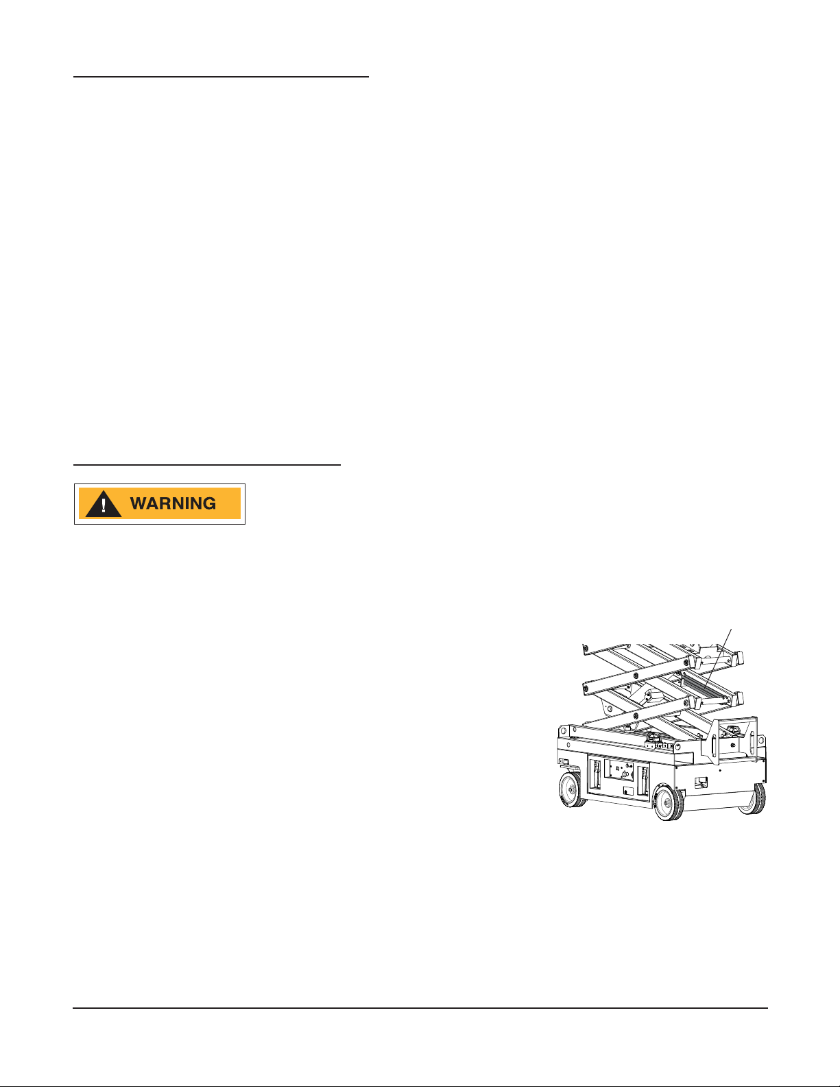
Li and Support the Machine.........................................................................................XII
Section 1: Maintenance PAGE
Machine Maintenance – General ............................................................................. 1-2
Pre-Start Inspecon Checklist ...................................................................................... 1-3
30-Day Service.............................................................................................................. 1-3
Frequent Inspecon Checklist ...................................................................................... 1-3
Hydraulic Fluid.............................................................................................................. 1-3
Baeries ....................................................................................................................... 1-4
Electrical Wiring ........................................................................................................... 1-5
Tires & Wheels ............................................................................................................. 1-6
Emergency Stop............................................................................................................ 1-6
Key Switch .................................................................................................................... 1-7
Horn.............................................................................................................................. 1-7
Drive Brakes.................................................................................................................. 1-7
Drive Speed - Stowed ................................................................................................... 1-8
Drive Speed - Raised..................................................................................................... 1-8
Drive Speed - Slow........................................................................................................ 1-9
Hydraulic Oil Analysis ................................................................................................... 1-9
Tank Venng System..................................................................................................... 1-9
Annual Inspecon Checklist ....................................................................................... 1-10
Scissor Slide Blocks.........................................................................................1-10
Hydraulic Tank Breather Cap...........................................................................1-11
Hydraulic Oil Inspection .................................................................................1-11
Section 2: Error Codes & Troubleshooting PAGE
Control Component Locations .................................................................................. 2-2
Fault Code Display ........................................................................................................ 2-3
Fault Codes Overview................................................................................................... 2-4
Troubleshoong Table .................................................................................................. 2-5