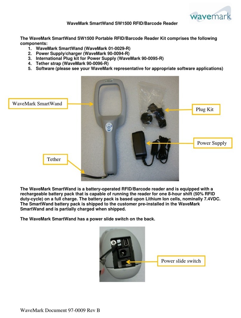
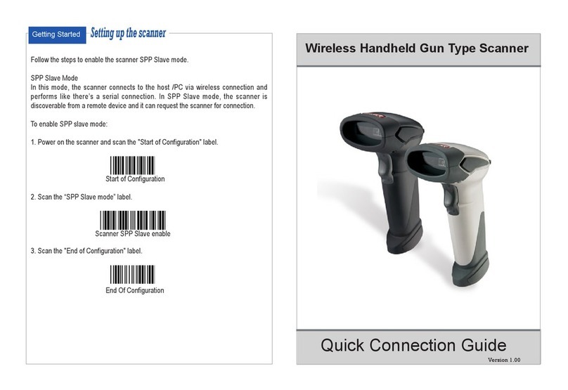
Godex AP16-F User manual

USER MANUAL AP16-F
AP16-F SEMI-AUTOMATIC BOTTLE APPLICATOR
User Manual Version: 1.2
Issued: July 2022

AP16-F User Manual V1.2
Page 2of 20
Content
Content...................................................................................................................................................... 2
1. Introduction ........................................................................................................................................... 3
2. Proper usage ......................................................................................................................................... 3
3. Safety...................................................................................................................................................... 3
3.1 Applied harmonized standards and the safe use of electrical appliances................................... 3
3.2 The possible risk of electric shocks whilst working with the AP16-F ............................................... 4
3.3 Precautions to ensure a safe operation ......................................................................................... 4
4. Specifications......................................................................................................................................... 5
4.1 Labels................................................................................................................................................ 5
4.2 Products............................................................................................................................................ 5
4.3 Electrical and physical specifications ............................................................................................ 5
5. Scope of delivery .................................................................................................................................. 5
6. AP16-F Configuration ............................................................................................................................ 6
7. Preparation of the device .................................................................................................................... 8
7.1 Installation......................................................................................................................................... 8
7.2 Media loading.................................................................................................................................. 8
8. Operation of the device....................................................................................................................... 9
8.1 General information ........................................................................................................................ 9
8.2 Sensor calibration ............................................................................................................................ 9
8.3 Label settings (1-Label Mode) ...................................................................................................... 11
8.4 Label settings (2-Label Mode) ...................................................................................................... 13
8.5 Product loading ............................................................................................................................. 18
8.6 Test Cycle ....................................................................................................................................... 18
8.7 Saving settings for later usage ...................................................................................................... 19
8.8 Display brightness and contrast.................................................................................................... 19
8.9 Service menu.................................................................................................................................. 19
9. Maintenance and service ................................................................................................................ 19
10. Warranty............................................................................................................................................. 20
11. Disposal of the device and its packaging....................................................................................... 20
12. Contact.............................................................................................................................................. 20

AP16-F User Manual V1.2
Page 3of 20
1. Introduction
You must inform yourself regarding the safe operation of electrical appliances in general and regarding the
characteristics and functions of the AP16-F in particular, before you operate the device. It is necessary to read
and follow the safety and operating instructions in this manual. In case the operator will be a third party, the
latter should be made acquainted with the content of this manual before operating the device as well.
2. Proper usage
The machine is designed to apply one or two self-adhesive labels at once to cylindric objects of different
diameter and length. The label application surface must be smooth. In case of applying front and back labels
simultaneously, the distances between the labels on the liner must be constant. Make sure you load the media
acc ording to this manual and calibrate the device for each different label type and size. You can then place
the target product underneath the pressure arm onto the product rollers. Make sure that the product will not
interfere with the applicator body when rotating, and that no part of the product will cause eccentric rotation.
Once you push the start-button or activate the foot pedal, the device will peel off the label(s) and apply them
to the rotating product. After the label has been fully applied, the AP16-F will stop rotating. You can then
remove the product and repeat the procedure. Any other use than the one described here is considered
improper and may generate significant risk of accident as well as void the warranty. The manufacturer accepts
no responsibility for faults, harm or damages caused by such improper usage.
3. Safety
3.1 Applied harmonized standards and the safe use of electrical
appliances
• AP16-F are class I electrical devices in terms of the necessary protection against electric shock in
accordance with harmonized standard EN 61140, ed. 2 and hence also meet generally acknowledged
standards such as, but non only CE, meaning that all non-live conductive parts are mutually conductively
connected and are further connected to the protective earth conductor of the device’s power supply.
Other harmonized standards that have been applied, are EN 60439-3, applicable to low-voltage switch
gear and EN ISO 12100 regarding the safety of machinery.
• Connection to the power network supply must be made in compliance with the requirements
specified in regulations and technical standards valid and applicable in the country of operation.
• Any work on the device may only be performed by persons who are duly qualified according to the
legislative code of the country where the device is installed and who, in addition, has been acquainted to
the necessary extent with the device.
•The keeper of the device is obliged to secure the performance of inspections of the electrical device in
accordance with the legislation regarding such inspections applicable in the country of operation.
•Disconnect from the main power source before removing stuck labels, cleaning or any other
maintenance.
• Do not use the appliance in humid conditions.
AP16-F User Manual V1.2
Page 4of 20
•Do not use the appliance in places where there is a risk of fire or explosion.
•Do not use the appliance with a damaged or dysfunctional power switch.
•If you do not use the appliance, remove the plug from the mains power socket.
3.2 The possible risk of electric shocks whilst working with the AP16-F
Despite the appliance being manufactured in accordance with relevant technical regulations pertaining to
safety, its technical design cannot preclude all risks that may occur, especially in the event of careless or
negligent behavior during use of the device. The device must be used with full awareness of the following
risks of electric shock:
• Resulting from direct or indirect contact with parts designed to conduct electric current (live parts) during
the removal of electric equipment covers.
•In the event of damage caused to insulating parts such as movable power cords.
• Caused by damaged parts of electrical components.
•In the event of spilling liquids onto the device.
•Insertion of objects into the housing of the device.
3.3 Precautions to ensure a safe operation
• Do not apply labels to damaged and/or irregularly shaped items.
• Do not apply labels to damaged items of any kind.
• The device must be switched off during media loading.
•Switch off the device before doing any cleaning or maintenance.
• Do not touch the product rollers unless the device is switched off.
•Do not insert products while the de product rollers are rotating.
• Do not start the device with a product placed incorrectly.
•Do not remove the product before the rollers stopped rotating.
• Do not use labels which are not in accordance with the specifications of the AP16-F.
• Do not apply labels to items which are not in accordance with the specifications of the AP16-F.
•Keep your workplace in order. Clutter in the work area can lead to accidents.
•Ensure good lighting at your workplace.

AP16-F User Manual V1.2
Page 5of 20
•Keep bystanders, especially children, away from the appliance when operating it.
•Take a secure posture, keep balance.
•Carefully maintain your appliances.
•Treat your work with caution. Do not use the device if you are not concentrated enough.
Any lack of compliance with these precautions may cause injury as well as damage to your equipment and
products.
4. Specifications
4.1 Labels
• Length: 25mm –500mm
• Width: 25mm –150mm
• Cores: 46mm –76mm
• Outside diameter: up to 200mm
• Gap width: minimum 2,5mm
4.2 Products
• Length of cylindric surface: 25mm –240mm / minimum 0.5 x diameter
• Total product length: depending on shape and diameter
• Diameter: 25mm –160mm
4.3 Electrical and physical specifications
• Supply voltage: 220V –240V AC, 50Hz
• Consumption: <100W (operation) / <35W (standby)
• Noise level: <70dB.
• Environmental temperature (operation): 10°C - 30 °C
• Storage temperature: 0°C - 60 °C
• Operational air humidity: 0% - 60 %
• Dimensions (LxWxD): 365mm x 330mm x 245mm
• Weight: 12Kg
5. Scope of delivery
Check whether the delivery is complete:
1x AP16-F Applicator: 1x 240V power cable: 1x Food pedal with cable: 1x Quick guide:

AP16-F User Manual V1.2
Page 6of 20
6. AP16-F Configuration
Picture 1.0
1. Product support roller.
2. Product drive roller.
3. Product positioners.
4. Liner drive roller.
5. Liner pressure roller.
6. Product pressure arm.
7. Label roll positioners.
8. Label roll holder.
9. Label roll brake.
10. Control panel.
11. Start button.

AP16-F User Manual V1.2
Page 7of 20
Picture 2.0
6. Product pressure arm.
7. Label roll positioners.
12. Label sensor.
13. Power switch.
14. Power connector.
15. Label guide rod.
16. Label guides.
17. Foot pedal connector.

AP16-F User Manual V1.2
Page 8of 20
7. Preparation of the device
7.1 Installation
The AP16-F should be placed on a flat, horizontal surface larger than its base. There must be sufficient space
around the device for normal operation and maintenance. Insert the included power cord into the connector
on the back panel (Pic. 2, no. 14), and connect it with a 220V-240V AC mains socket. In case you wish to use
the foot pedal, plug its connector into the socket on the back side of the AP16-F as well (Pic. 2, no. 17). Then
install the media. For safety reasons we highly recommend switching on the device AFTER installing the media.
7.2 Media loading
Picture 3.0
Hint: measure the label lengths and gap lengths and calculate the required stop positions before you load the
media. See paragraph 8.3 and 8.4 how to calculate the correct stop positions.
Remove the label roll holder (Pic. 1, no. 8) from the device, insert it into your label roll and place it back. Use
the label roll positioners (Pic. 1, no. 7) to align the media according to the desired position on the product.
Lead the media through the AP16-F according to picture 3.0. The labels must face the bottom side of the
applicator, go underneath the label guide rod, through the sensor and around the peeling edge. To lead the
media between the liner drive roller and pressure roller, you disengage the latter by pulling it towards you. You
then pull the liner over the label roll and let the liner pressure roller engage again.
Now switch on the device.

AP16-F User Manual V1.2
Page 9of 20
8. Operation of the device
8.1 General information
Hint: position the front edge of the label near the peeling edge. In case of applying 2 labels to each product
this must be the longest label of the two.
At first start-up the display will show the following screen:
You now select the language, the application mode (one or two labels), and you enter the label settings
according to the instructions in chapter 8.
The AP16-F automatically stores the settings you have applied in so-called “programs”. When you start the
AP16-F again, the display will automatically show the last “program”you have used.
Apart from creating programs in the menu, you will calibrate the ultrasonic sensor for each new label material
which you will use.
-calibrate the sensor according to parapgraph 8.2.
-for label and product settings in 1-label mode: see paragraph 8.3.
-for label and product settings in 2-label mode: see paragraph 8.4.
8.2 Sensor calibration
Gap sensor values:
Picture 4.0
First place the sensor over the gap as shown in
picture 4.0. Make sure that line “B” is in the middle of
the gap and that line “A” crosses the narrowest gap
section. Also ensure that no label cut outs, other than
the gaps, will interfere with line “A” during operation.
Do not move the labels or sensor during calibration.
Press and hold the “TEACH” button for >3 seconds.
The LED “T” will shine, which indicates the sensor is in
calibration mode. Once you release the key, LED “T”
will start blinking. The sensor is now teaching itself the
gap value. The LED-bar will indicate the signal
strength. After the process is completed, LED “T” will
go off.
In case the signal strength is insufficient the LED-bar
will start blinking. Repeat the procedure in that case.
You may need to restart the device.

AP16-F User Manual V1.2
Page 10 of 20
Label sensor values:
Picture 5.0
Calibration check: Picture 6.0
After measuring the gap, you must measure the
labels.
Place the sensor over the label as shown in picture
5.0. Make sure that line “B” is in the middle of the
label and that line “A” crosses the narrowest gap
section. Also ensure that no label cut outs, other
than the gaps, will interfere with line “A” during
operation. Do not move the labels or sensor during
calibration.
Press and hold the “TEACH” button for >3 seconds.
The LED “T” will shine, which indicates the sensor is
in calibration mode. Once you release the key, LED
“T” will start blinking. The sensor is now teaching
itself the label value. The LED bar will indicate the
signal strength. After the process is completed, LED
“T” will go off.
In case the signal strength itself or the difference
with the gap signal is insufficient, the LED-bar will
start blinking. Repeat the procedure in that case.
You may need to restart the device.
After calibrating the sensor, you check whether
the sensor detects the gaps correctly.
See picture 6.0. Move the labels back and forward
over line “A”. If the calibration has been successful,
LED “o” will shine each time when a gap is
underneath the sensor.

AP16-F User Manual V1.2
Page 11 of 20
8.3 Label settings (1-Label Mode)
I. Selecting 1-Label mode:
-Hold the “ ” button to enter the AP16-F menu
-Select the program you want to use or edit with the and buttons
-hold the “M” button to open the settings
-Select your language with the and buttons and confirm with the “M” button:
-Select 1-Label Mode and confirm:
II. Calculating the stop position:
The label sensor is located exactly 100mm from the peeling edge and its position is fixed. It is position “S” in
below pictures. Because labels have different lengths, we need to calculate the correct stop position, which
we enter in the display menu. The value depends on the length of the labels and the distance between them.
The most comfortable and fastest way to calculate both the stop position and rotation time is with our online
parameter calculator: https://godex.si/AP16-F/AP16_Calculator.html If not at your disposal, you must proceed
as follows:
There are 4 scenarios:
Picture 7.1: in scenario A the correct stop position is 100mm.

AP16-F User Manual V1.2
Page 12 of 20
Picture 7.2: in scenario B the correct stop position is 100mm.
Picture 7.3: in scenario C the correct stop position is 100mm minus the label length minus ½ gap length
Picture 7.4: in scenario D the correct stop position is 100mm minus the combined length of all the labels and
all the gaps, plus ½ gap length.
You now enter the calculated value in the display menu and confirm with button “M”:

AP16-F User Manual V1.2
Page 13 of 20
III. Setting the rotation time:
After confirming the correct stop position in the menu, you enter the rotation time in seconds and confirm. The
rotation time is the time the product rotates after the label sensor has detected the end of the label. Two
seconds is a convenient value for most labels. You may decrease the rotation time to speed up each
application cycle as long as you ensure each label is transferred and firmly attached to the product before
rotation stops.
You are now ready to do a test cycle (paragraph 8.6).
Note: the calculated stop positions are a good start. Tuning might be required once you start operating the
device.
8.4 Label settings (2-Label Mode)
I. Selecting 2-Label mode:
-Hold the “ ”button to enter the AP16-F menu
-Select the program you want to use or edit with the the and buttons
-hold the “M” button to open the settings
-Select your language with the and buttons and confirm with the “M” button:
-Select 2-Label Mode and confirm:

AP16-F User Manual V1.2
Page 14 of 20
II. Calculating the stop positions:
The label sensor is located exactly 100mm from the peeling edge and its position is fixed. It is position “S” in
below pictures. Because labels have different lengths, we need to calculate the correct stop position, which
we enter in the display menu. The value depends on the length of the labels and the distance between them.
The most comfortable and fastest way to define the stop positions, the label distancing and rotation time is
with our online parameter calculator: www.xxxxxxxxxx.yyy If not at your disposal, you must proceed as follows:
Stop position 1
You first determine the stop position of the “back label”. Hence, stop position 1 relates to the back label on
your product:
= back label position
There are 4 scenarios:
Picture 8.1: in scenario A the correct stop position of the back label is 100mm.
Picture 8.2: in n scenario B the correct stop position of the back label is 100mm.

AP16-F User Manual V1.2
Page 15 of 20
Picture 8.3: in n scenario C the correct stop position of the back label is 100mm minus the label length minus
½ gap length
Picture 8.4: in n scenario D the correct stop position of the back label is 100mm minus the combined length of
all the labels and all the gaps, plus ½ gap length.
Stop position 2
Now you calculate stop position 2. Stop position 2 relates to the front label on your product.
= front label position
The procedure is the same, but now you start measuring from the front end of a front label:
Picture 9.1: in scenario A the correct stop position of the front label is 100mm.

AP16-F User Manual V1.2
Page 16 of 20
Picture 9.2: in scenario B the correct stop position of the front label is 100mm.
Picture 9.3: in scenario C the correct stop position of the front label is 100mm minus the label length minus ½
gap length
Picture 9.4: in scenario D the correct stop position of the back label is 100mm minus the combined length of
all the labels and all the gaps, plus ½ gap length.
You now enter the calculated value in the display menu and confirm with button “M”:

AP16-F User Manual V1.2
Page 17 of 20
III. Setting the distance between front and back label on the product:
1. Go to “label spacing” in the display menu:
2. Calculate the circumference of the product by multiplying its diameter D with 3,14
3. Deduct the the front label length (L1) and the back label length (L2) from the circumference
4. Divide the result of step 3 by 2 and then once more by 10. The outcome L3 is the value you must enter.
Example: bottle diameter 90mm, front label 70mm, back label 50mm.
3,14 x 90mm = 282,6mm (circumference)
282,6mm –70mm –50mm = 162,6mm
162,6mm : 2 = 81,3mm
81,3mm : 10 = 8,13cm
Illustration:
This procedure will pace the front and back labels perfectly opposite to each other.

AP16-F User Manual V1.2
Page 18 of 20
IV. Setting the rotation time:
After confirming the correct stop positions 1 and 2 in the menu, you enter the rotation time in seconds and
confirm. The rotation time is the time the product rotates after the label sensor has detected the end of the
label. Two seconds is a convenient value for most labels. You may decrease the rotation time to speed up
each application cycle if you ensure each label is transferred and firmly attached to the product before
rotation stops.
You are now ready to do a test cycle (paragraph 8.6). Do so before loading a product.
Note: the calculated stop positions are a good start. Tuning might be required once you start operating.
8.5 Product loading
8.6 Test Cycle
Note: in “two label mode” the longest label must be applied first, regardless whether it is the front or back
label! Place the front end of the longest label near the peeling edge before you start.
Carry out the first cycle without a product loaded. After this first run, the front end of the next label-to-be-
applied should be within a few mm from the peeling edge. You may need to fine-tune the stop position. For
example polypropylene (pp) labels tend to be applied better when the front end projects over the peeling
edge. You might need to adjust both stop positions when in 2-label mode.
See picture 10.0. Lift the product pressure arm
and place the cylindric product on the
product drive and product support rollers. You
tune the distance between the driver and the
support roller to the product diameter in such
way it lays steady. The product pressure arm
height should also be adjusted to the product
diameter for easy loading. You do this by
pivoting the aluminum U-block which connects
the arm with the main frame.
During operation you will just pull the pressure
arm slightly up to remove and insert products.
The coil springs will push it back onto the
products.
The orientation and exact position of the
product on the rollers depend on the desired
label position and direction.
We recommend to first do a test cycle before
you start serial production.
Picture 10.0

AP16-F User Manual V1.2
Page 19 of 20
The application cycle is initiated by either pressing the red start button on the device housing or activating the
foot pedal. The number of labels which has been applied appears on the display. You reset the counter by
pressing the “C”button during 3 seconds.
Once you have verified the correct start position of the label(s), you can start the serial application of labels,
although still some fine-tuning might be required once the product has been loaded.
8.7 Saving settings for later usage
By entering settings for a particular label and product, you automatically create a “program” which is saved
in the memory. When you use the AP16-F the next time the device will take you to the program used the last.
To add more programs or edit them, you scroll up and down the list with the and buttons and select the
number of your choice. You can store 30 different programs.
Simply note the program number for a particular product, select it the next time and start labeling!
8.8 Display brightness and contrast
Pressing and holding the -key for 3 seconds will open the contrast adjustment mode. The contrast level is
indicated by a row of arrows (>>>> ...). You adjust it with the “C” and buttons:
By pressing the M-key, the desired value is saved and the display switches to the brightness settings.
You can now also adjust the brightness with the “C” and buttons.

By pressing the M-key, you leave this menu.
8.9 Service menu
The AP16-F has also a password protected service menu, only accessible for authorized service technicians.
9. Maintenance and service
Attention: Risk of injury! Always switch off the device and disconnect it from the mains power network before
performing any work on the machine.
The AP16-F does not require any technical maintenance within its specified service life.
Use a dry brush or cloth to remove dust and other dirt after each usage. Do not use solvents to clean any of
the surfaces. Alcohol may be used to clean the shafts. Keep liquids from entering the housing. Make sure that
the vents are always clear.
The device should be serviced by qualified personnel only and only using original spare parts.
If the power cord is damaged, replace it with a new one to avoid electric shock and possible defects to the
Device.

AP16-F User Manual V1.2
Page 20 of 20
10. Warranty
The AP16-F must be used for its intended purpose only, under the specified climatic conditions, in an
environment without aggressive liquids and gases that might damage paint or parts. In case you need to
announce a warranty claim, contact your certified GoDEX supplier.
The warranty period is 36 months from the date of purchase by the end-user / parts only. The warranty applies
to manufacturing defects and related premature wear only. Damage caused by transportation, normal wear
and tear and the damage to fragile parts are not covered by the manufacturer’s warranty. Damage caused
by abuse and service interventions by uncertified GoDEX or GoDEX partners personnel will void the warranty.
Spare parts come with 12 months warranty.
The device should always be transported in its original packaging to avoid damage.
11. Disposal of the device and its packaging
The packaging is made from environmentally friendly materials, suitable for recycling.
Do not dispose of electrical appliances with household and other general waste. According to European Union
Directive 2002/96 / EU (WEEE), end-of-life electrical appliances must be collected separately and prepared for
recycling in accordance with environmental protection requirements.
12. Contact
GoDEX Europe GmbH, Industriestraße 19, 42477 Radevormwald, Germany, tel. +49 2195 595 990,
e-mail: [email protected],
Table of contents
Other Godex Barcode Reader manuals

Godex
Godex EZ-1000 Plus User manual

Godex
Godex EZ-1100Plus User manual

Godex
Godex GS220 User manual

Godex
Godex RT700i User manual

Godex
Godex BP300 User manual

Godex
Godex EZPi1000 Series User manual

Godex
Godex HD90 User manual

Godex
Godex G300 User manual

Godex
Godex RT200i User manual

Godex
Godex RT700 SERIES User manual

Godex
Godex ZX1200i User manual

Godex
Godex RT700i User manual

Godex
Godex GS550 User manual

Godex
Godex G525 User manual

Godex
Godex GS220 User manual

Godex
Godex GS550 User manual

Godex
Godex GS500 Operating and maintenance instructions

Godex
Godex G500 User manual

Godex
Godex GS200 User manual

Godex
Godex GS520 User manual