Gomax MX-1003A User manual

MX-1003A
Dual-View Video Processor
User Manual
Made in Taiwan

Safety and Notice
The MX-1003A Dual-View Video Processor has been tested for conformity to safety regulations and
requirements, and has been certified for international use. However, like all electronic equipments, the MX-1003A
should be used with care. Please read and follow the safety instructions to protect yourself from possible injury
and to minimize the risk of damage to the unit.
Follow all instructions and warnings marked on this unit.
Do not attempt to service this unit yourself, except where explained in this manual.
Provide proper ventilation and air circulation and do not use near water.
Keep objects that might damage the device and assure that the placement of this unit is on a stable surface.
Use only the power adapter and power cords and connection cables designed for this unit.
Do not use liquid or aerosol cleaners to clean this unit. Always unplug the power to the device before
cleaning.

~ 1 ~
General
The MX-1003A Dual-View Video Processor is an advanced video processor for multimedia presentations. It
is an ideal solution for applications where two video signals must be displayed on a single display. It supports up
to four video inputs, of which two can be outputted simultaneously in Picture-In-Picture (PIP) or
Picture-Aside-Picture (PAP) modes. The MX-1003A allows you to manipulate output images, wherever position
and whatever sizes you want for viewing two computers or two video signals or a combination.
The embedded scaler converts signals from input sources to match the native resolution of monitors, flat
panel displays, projectors as well as user-selectable output settings up to WUXGA (1920x1200). Dual outputs are
provided in both analog (VGA) and digital (DVI) format, one is connected to remote display and the other is
connected to on-site display for real time monitoring.
Figure 1: Configuration Diagram
Introduction

~ 2 ~
Features
Four graphic (DVI / VGA) and two video (Component / Composite) Inputs, from 640x480 to 1920x1200,
interlaced or progressive.
Dual outputs (DVI / VGA), 640x480 to 1920x1200.
PIP, PAB, Full screen modes and adjustable size& position through software.
Titles, borders and colored backgrounds.
Resize, position, flip, zoom& pan and blend output video.
Can be cascaded to obtain more images.
Image parameters and layouts are automatically saved in flash memory and can be recalled for later use.
Several Image parameters and layouts can be saved in flash memory and can be recalled for later use.
Video parameters adjustable (brightness, contrast, color temperature, etc.).
User-selectable output settings, up to 1920x1200.
Perfectly as a video screen splitter, a video converter and a video switcher.
Firmware upgradable for support of new features and technology enhancements.
IR control and software control through RS-232.
Portable size.
Automatically power-saving mode.

~ 3 ~
Specifications
Model Name
MX-1003A
MX-1003A
Technical
Role of usage
Multiplexer / video processor
Dual output support
Yes [DVI + VGA]
HDCP compliance
No
Video bandwidth
DVI [Single-link 4.95Gbps] VGA [165MHz]
Component [30MHz] Composite [13.5MHz]
Video support
480i / 480p / 720p / 1080i / 1080p60 / 1920x1200@75 / 1600x1200@60
Audio support
No
Control
RS-232 and IR
PIP / PAP
Yes
Cascadable
Yes
Input TMDS signal
1.2 Volts [peak-to-peak]
ESD protection
Human body model —±15kV [air-gap discharge] & ±8kV [contact discharge]
PCB stack-up
6-layer board [impedance control —differential 100; single 50]
Input
2x VGA + 2x DVI + 1x component +
1x composite + 1x RS-232
2x VGA + 1x DVI + 1x component +
1x composite + 1x RS-232
Output
1x DVI + 1x VGA
IR remote control
Electro-optical characteristics: = 25/ Carrier frequency: 38kHz
DVI connector
DVI-I [29-pin female, digital only]
VGA connector
HD-15 [15-pin D-sub female]
RS-232 connector
DE-9 [9-pin D-sub female]
RCA connector
75female
Mechanical
Housing
Metal case
Dimensions
(L x W x H)
Model
180 x 103 x 23mm [7.1” x 4” x 0.9”]
Package
330 x 200 x 95mm [1’1” x 7.9” x 3.7”]
Carton
495 x 440 x 380mm [1’7.5” x 1’5.3” x 1’3”]
Weight
Model
480g [1.1 lbs]
Package
1345g [3.0 lbs]
Fixedness
Wall-mounting case or wall hanging holes upon request
Power supply
5V 4A DC
Power consumption
10 Watts [max]
Operation temperature
0~40C [32~104F]
Storage temperature
-20~60C [-4~140F]
Relative humidity
20~90% RH [no condensation]
Package Contents
1x MX-1003A or MX-1003A
1x DVI to DVI&VGA breakout cable
1x VGA to component breakout cable
1x VGA to DVI adapter
1x 5V power adapter
1x IR remote controller
1x Installation software CD
1x User Manual

~ 4 ~
Package Contents
1. MX-1003A
2. DVI to DVI & VGA breakout cable
(DDVY01)
3.VGA to component breakout cable
(VYPBA01)
4. DVI to VGA adapter (DVA01)
5. 5V DC power adapter
6.IR remote controller
7. Installation software CD
8. User Manual
Please visit www.gomax-electronics.com/download.htm to download software
& firmware updates

~ 5 ~
Inputs and Outputs
The MX-1003A has four inputs and accepts both graphics and video signals, which come from computers
and NTSC/PAL video sources respectively. There is a concept of main channel and sub channel for this device.
You can pick up two of the four inputs, one is for main channel and the other is for sub channel, and then display
two of them simultaneously on the same screen. Figure 2 shows the rear panel connectors of a MX-1003A and
Table 1 illustrates how you can connect video devices and display to the MX-1003A.
Figure 2: Rear Panel
1. Power connector 4. Composite input
2. DVI / VGA output 5. DVI / VGA / Component input
3. DVI / VGA input 6. DIP switch*(for firmware & system reset)
*Default: Turn on the MX-1003A then switch both two DIP switches simultaneously up and down
to factory default mode.
*These IO ports support various resolution from 640x480 up to 1920x1200, for more detail of
the supported modes, please refer to the Appendix –Supported Resolution.
Table 1: I/O Connectors
Input Connector
Video Source
DVI-IN
[1] DVI
[2] VGA —with a DVI-to-VGA adapter (DVA01)
[3] Component (YPbPr) —with a DVI-to-VGA adapter (DVA01) and a VGA-to-component
breakout cable (VYPBA01)
[4] 1x DVI + 1x VGA —with a DVI-to-DVI/VGA breakout cable (DDVY01)
[5] 1x DVI + 1x Component (YPbPr) —with a DVI-to-DVI&VGA breakout cable (DDVY01)
and a VGA-to-component breakout cable (VYPBA01)
DVI-I IN 2
[1] DVI
[2] VGA —with a DVI-to-VGA adapter (DVA01)
Composite
[1] With a RCA cable
Output Connector
Display
DVI-I OUT
[1] DVI display
[2] VGA display —with a DVI-to-VGA adapter (DVA01)
[3] 1x DVI display + 1x VGA display —with a DVI to DVI&VGA breakout cable (DDVY01)
+5V DC
1
5
4
3
2
6

~ 6 ~
Safety Precautions
I. To prevent fire or shock hazards, do not expose this device to rain or moisture.
II. When connecting other products such as DVD players, and personal computers, you should turn off the
power of this product for protection against electric shocks.
III. The product should be placed more than one foot away from heat sources such as radiators, heat registers,
stoves, and other products (including amplifiers) that produce heat. In addition, do not cover any material or
devices on the top of the device.
IV. Do not use immediately after moving from a low temperature to high temperature, as this causes
condensation,
V. Do not place this product on an unstable cart, stand, or table. The product may fall, causing serious injury to
a child or adult and serious damage to the product.
VI. Unplug this product from the wall outlet before cleaning. Do not use liquid cleaners or aerosol cleaners. Use
a damp cloth for cleaning.
VII. Do not allow the same still picture to be projected for a long time or an abnormally bright video picture to be
projected. The video image could be burned in to the display device.
Installation Procedures
Unpacking
Remove the MX-1003A from the shipping container and examine it for any signs of shipping damage or
missing items (check with package contents above). All shipping items should be saved if the product is to be
moved or returned for service. Shipping unit back to dealers for service not in the original box may result in
voiding warranty or additional cost.
Placement
The unit uses convection to cool. A fan is not needed, so do not block the sides of this device or stack
another device on the top or bottom of the MX-1003A.
Connections
We recommend the highest quality cables for both input and output connections.
1. Switch off the MX-1003A and all devices that you want to connect.
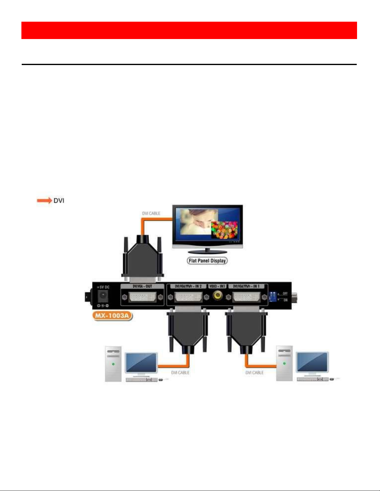
2. Connect a monitor, a projector or other displays that comes with DVI and/or VGA inputs by using 1
male-to-male DVI (VGA) cable to MX-1003A DVI output (you can connect 2 displays equipped with DVI and
VGA respectively by a DVI to DVI/VGA breakout cable (DDVY01)) .
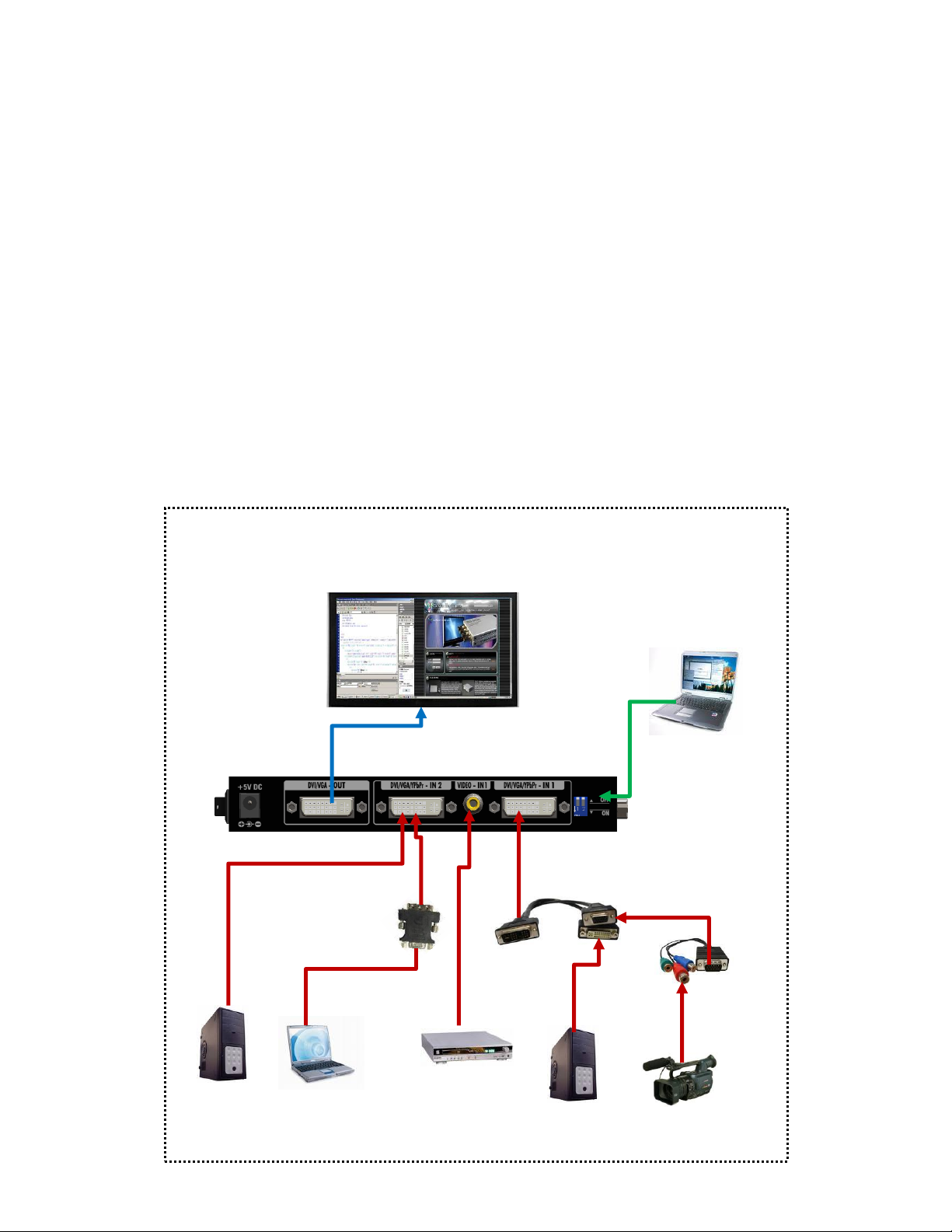
3. Plug in DVI to DVI/VGA breakout cable (DDVY01) to DVI-IN and plug in VGA to component breakout cable
(VYPBA01) to the VGA connector of the breakout cable.
Hardware Installation

~ 7 ~
4. Connect a device equipped with DVI output (such as PC) to the DVI connector of the breakout cable.
5. Connect a device equipped with component video output (YPbPr such as DVD player or camera) to the
3-RCA jack of the VYPBA01.
6. Connect a device equipped with VGA output (such as laptop) to the VGA connector of MX-1003A.
7. Connect a device equipped with composite video output to composite input of the MX-1003A.
8. Connect your computer with the MX-1003A by a 9-pin RS-232 cable and then install the software.
9. Plug in power adapter cable into 5V DC power jack.
10. Switch on all devices connected and then switch on the video processor and then press “menu” to display
OSD menu.
11. Press down arrow key dropping down sub-menu to select the first channel (Main Channel) video/graphic
source.
12. Once the Main Channel has a video selected, press “exit” key to exit the sub-menu, and then move right to
the next item of OSD menu, which allows you to select the second channel (Sub Channel).
13. For detailed IR remote control operation, please refer to the On Screen Display menu and IR operating
instruction.
Figure 3: Connection Diagram
Component video
YPbPr
DVI
VGA
Composite video
CVBS
Software control
DVI or VGA Display
Connect to RS-232
DVI

~ 8 ~
IR Remote Control
The MX-1003A is now shipped with a compact remote control that allows for direct access to most
commands used to control the video processor.
(1)
Power
Power on/off the device
(2)
PIP Border
Display the border of small image (under PIP mode)
(3)
Up Button
Move to the upper titles
(4)
Source
Press to select a source for main channel
(5)
Reset
Factory Reset
(6)
Right Button
Move to the right titles
(7)
Menu
Display OSD menu
(8)
Left Button
Move to the left titles
(9)
Logo
Display a logo
(10)
Exit
Move back to previous option or exit OSD menu
(11)
Down Button
Move to the lower titles
(12)
Enter
Press to drop down sub-menus or confirm the
selection
(13)
Blank
Blank out the screen
(14)
Color
Automatically configure the main channel color
(15)
Auto
Automatically configure the main channel position
(16)
V Flip
Flip vertically
(17)
H Flip
Flip horizontally
(18)
SWAP
Swap between main channel and sub-channel
(only works in PIP or PAP mode)
(19)
PIP
Change modes among full screen, PIP, PAP
(20)
Sub Pause
Freeze sub-channel
(21)
Main Pause
Freeze main channel
(1)
(2)
(3)
(4)
(5)
(9)
(13)
(14)
(18)
(10)
(7)
(8)
(11)
(12)
(16)
(17)
(21)
(20)
(20)
(6)
(15)
(19)

~ 9 ~
On Screen Display Menu
Menu
Main Control
OSD
Control
Language
Selection
Main
Source
Enter Button
Down
Button
Factory
Reset
Main
Sub
Resolution
Selection
Sub Source
Enter Button
Down Button
Sub Control
Display
Image
Position
Color
PIP
Control
Logo
Border

~ 10 ~
Main Source: Select an input source for the main channel (VGA / YPbPr, DVI, Composite, VGA)
Main Control:
Display
Brightness (Slider) Hue (Slider) Saturation (Slider)
Contrast (Slider) Flesh-tone (Button: Off, Weak, Soft, Strong)
Image
Scaling (1:1, Fill, Aspect, Panor) Angle Filtering (Button: Off, On)
Adaptive Deinterlacing (Button: Off, Level 1, Level 2, Level 3) Film Mode Detect (Button: Off, On)
Noise Reduction (Button: Off, Low, Med, High) Sharpness (Slider)
Position
Zoom(Button: In, Out) Zoom Vertical Pan (Button: Down, Up)
Zoom Horizontal Pan (Button: Left, Right) Vertical (Slider) Horizontal (Slider)
Color
sRGB (Button: Off, On Cl.BA) Red (Slider)
Gamma Correction (Button: Off, 2.2, 2.4) Green (Slider)
Color Temperature (Button: User, 6500K, 9300K) Blue (Slider)
PIP Control
PIP Mode (Off, Single, PAP) Vertical (Slider) Blend (Slider)
PIP Size (Small, Medium, Large) Horizontal (Slider)
Logo (Off, On)
Border (Off, On)
Red (Slider) Green (Slider) Blue (Slider) Width (Slider)
Sub Source: Select an input source for sub-channel (VGA/component, DVI, composite, VGA)
Sub Control: The same as Main Control
OSD Control: Vertical (Slider) Horizontal (Slider) Blend (Slider)
Time out (Slider) OSD Zoom (On, Off)
Language Selection: English and Traditional Chinese
Factory Reset: Reset the device to default
Resolution Selection: Press Down Button to select an output resolution and then press enter to confirm that
selection.
800×600 @60Hz 1280×768 @60Hz 1440×900 @60Hz 1920×1080 @50Hz
1024×768 @60Hz 1280×1024 @50Hz 1400×1050 @50Hz 1920×1080 @60Hz
1152×864 @75Hz 1280×1024 @60Hz 1400×1050 @60Hz 1920×1200 @50Hz
1280×720 @50Hz 1366×768 @60Hz 1600×1200 @60Hz 1920×1200 @60Hz
1280×720 @60Hz
Resolution
Selection
Border

~ 11 ~
System Requirement and Precautions
1. The MX-1003A provides a software control program which runs under Microsoft Windows 98, 2000, XP
through the interface of RS-232 serial control.
2. Before you click on the icon of the software, make sure you have secured the connection between your
computer COM port and the MX-1003A and switched on the MX-1003A with green LED light.
3. The MX-1003A has remote control and software control. To make sure all information shown in the software
is synchronized with those in the device, please click “Connect” to acquire the latest data from the MX-1003A
after you press any key on the remote control.
Instruction of Software Connection
1. Power up the MX-1003A and you can see both red and green LEDs on the front panel blink. Make sure the
serial port (RS-232) connection secure.
2. The first step after running the software is to automatically detect if the device responses correctly through
RS-232 port. The process takes 15-20 seconds. If the response is not accurate, a warning window will show
up as the figure below.
The possible reasons causing this failure could be:
The MX-1003A is not supplied with power or the MX-1003A enters deep sleep state. Please check the current
status, and reboot the MX-1003A
The serial connection through RS-232 is not well established or some other software has taken the available
serial ports. Please make sure the RS-232 cable is well connected and the available serial port is free to be used
by the MX-1003A.
Operation Software

~ 12 ~
3. If the serial connection is well established, you can see similar work window as below.
4. While you move the mouse’s cursor near the borders, in either red or blue, the icon of the cursor will change
as the figure below.

~ 13 ~
Instruction of Software Operation
File
a. Connect: This will synchronize the status of the MX-1003A with that
of the software, especially after IR commands sent.
b. Save Setting: This will save current user preferred settings such as
the positions and sizes of the videos, the width or color of border etc.
into your favorite setting files.
c. Load Setting: The function will load the favorite settings from the
previously saved file.
d. IR Control: This will enable or disable the IR remote control.
e. Auto Sleep: This decides if the MX-1003A enters the deep sleep mode if the video signal cannot be detected
in the main channel.
f. Device ID: This is for identifying the MX-1003A while multiple devices are cascaded by RS-232 over CAT5
module.

~ 14 ~
g. Factory Reset: This will restore all the system values back to the factory default.
h. Exit: Quit the software.
Background
a. Resolution: Change the output resolution.
b. Layout: The preset layout for main & sub channels.
c. HFlip: Horizontally flip the output video.
d. VFlip: Vertically flip the output video.
e. SWAP: Swap the main and sub channel.
f. Color: The background color selection.
g. Custom Size 1-3: Save or read main/sub channel size, position, visible and Layer.
1. Assign an ID for the connected MX-1003A: type a number in the “ID
Number” of the device ID setting area and then click “Write”.
2. Read the ID of the connected MX-1003A: click “Read” and the ID will show
up.
3. Super Control: all devices cascaded will receive and respond the same way
when you are operating the control software.
4. Single Device Control: remove the check beside the “Super Control” and
type a number that represent a specific MX-1003A and then click “Apply”.
Exit the “Device ID Setting” and click “Connect”.

~ 15 ~
Main
a. Input Source: Select a video/graphic input of the
main channel.
b. Visible: Display the main channel or not.
c. Border: Display the main channel’s border.
d. Label: Display the main channel’s label. Users
can define the content of the label.
e. Layer: This will make the main channel overlays
the sub channel.
f. Pause: Freeze the display of the main channel.
g. Full Screen: Display the main channel full
screen.
h. Color Balance: Automatically do the color
balance while the main channel’s input is from
VGA/component.
i. Auto Config.: Automatically do the auto
adjustment while the main channel’s input is
from VGA/component.
Sub
a. Input Source: Select a video/graphic input of the
sub-channel.
b. Visible: Display the sub-channel or not.
c. Border: Display the sub-channel’s border.
d. Label: Display the sub-channel’s label. Users can
define the content of the label.
e. ayer: This will make the sub-channel overlays the
main channel.
f. Pause: Freeze the display of the sub channel.

~ 16 ~
Control- Setting Dialog
Border
Select main or sub channel for further setting.
PAP mode only
1. Border Color: Setup border’s color by clicking on “Color
setting”.
2. Border Width: Input border’s width.
3. Border Type: The placement of border has two types:
Option Inside means the added border is fully inside the
video. Option Outside means the added border is
completely outside the video and this added border can
overlay the other video input.
4. Text Color: Select the color of the label by clicking on
“Color Setting” button.
5. Text Auto: While selecting “Text Auto”, the label on the
screen for each channel will display its corresponding
input channel type. While unselecting “Text Auto”, users
can input the desired string to be displayed.
Only 15 English characters can be displayed at most.

~ 17 ~
6. Duty Cycle: The duty cycle of blinking of OSD borders and
labels.
7. Frequency: How fast the blink.
Image
1. Choose the scaling type for the main channel at full screen display.
2. While Blend is selected, users can use the slider to control the degree of blending.
There is a short period of slight blinking while the MX-1003A processes the blending of the two input
videos.

~ 18 ~
Color
1. Select the main or sub channels.
2. Reset: Restore all the setting on this page back to
their default values.
Zoom
A. Select the main or sub channel.
B. Default: Restore the selected channel without zoom
effect.
A
B
Table of contents
Other Gomax Media Converter manuals

Gomax
Gomax VW-1404CZ User manual

Gomax
Gomax VW-1404ZH-C User manual

Gomax
Gomax CV-53BI User manual

Gomax
Gomax MX-2000A User manual

Gomax
Gomax MX-2003B User manual

Gomax
Gomax HUB-66U User manual

Gomax
Gomax VW-1404ZH User manual

Gomax
Gomax SP-5002VZC User manual

Gomax
Gomax CV-5005H User manual

Gomax
Gomax CV-503ZK-A User manual

Gomax
Gomax CV-503SZ User manual

Gomax
Gomax CV-305VS User manual

Gomax
Gomax CV-305P User manual

Gomax
Gomax SP-5002PZ User manual

Gomax
Gomax CV-105 User manual

Gomax
Gomax CV-C05S User manual

Gomax
Gomax CV-915 User manual

Gomax
Gomax MT-305A User manual

Gomax
Gomax CV-53AK User manual

Gomax
Gomax CV-503ZKM User manual