manuals.online logo
Brands
  1. Home
  2. •
  3. Brands
  4. •
  5. Graco
  6. •
  7. Engine
  8. •
  9. Graco 215-354 User manual

Graco 215-354 User manual

INSTRUCTIONS–P
ARTS LIST
307–361
Rev C
Supersedes
B
This
manual contains IMPORT
ANT
WARNINGS AND INSTRUCTIONS
READ AND RETAIN FOR REFERENCE
GRACO INC. P.O. BOX 1441 MINNEAPOLIS, MN 55440–1441
COPYRIGHT
1979, GRACO INC.
AIR
MOT
OR MUFFLERS
FOR
MONARK

AND PRESIDENT

AIR MOT
ORS
IMPORTANT
You
cannot order parts or request service and warranty infor
-
mation
for the complete pump without the information on the
serial
plate.
Record
all the information from the air motor and serial
plate
in
these spaces. Keep this manual in a
safe place as an extra
precaution.
LUFTMOTOR–AIR
MOT
OR
Model
Series
PAR
T NO.
PUMP MAX.GPM(l/MIN)
MAX AIR
PSI (bar)
SERIALSERIESRATIO
MODEL
215–354
Fits Monark Air Motors
Except Models 205–237, 205–471, and 207–546
MODEL 214–873, Series A
Fits President Air Motors
307–361
INSTALLATION
Pressure Relief Procedure
To
reduce the
risk of serious bodily injury
, including fluid
injection,
splashing in the eyes or on the skin, or injury
from moving parts, ALWAYS follow this procedure
whenever
you shut of
f the pump, and before installing,
removing, cleaning or servicing any part of your sys-
tem.
1. Engage
the gun’
s safety latch.
2.
Shut of
f the air to the pump.
3. Close the bleed–type master air valve (required in
your
system).
4.
Disengage the gun safety latch.
5. Hold a metal part of the gun firmly to the side of a
grounded metal pail, and trigger the gun to
relieve
pressure.
6.
Engage the gun safety latch.
7. Open the drain valve, having a container ready to
catch
the drainage.
8. Leave the drain valve open until you are ready to
spray
again.
If you suspect that the spray tip or hose is completely
clogged,
or that pressure has not been fully relieved af
-
ter following the steps above, VER
Y SLOWL
Y loosen
the
tip guard retaining nut or hose end coupling and
re
-
lieve
pressure gradually
, then loosen completely
. Now
clear
the tip or hose.
WARNING
NOTE: Reference numbers and letters in parentheses
in the text refer to Figs. 1 and 2 and the Parts
Drawings.
Unscrew
the plate retaining
screws and remove the iden
-
tification
plate (A) and warning plate (C) from both sides
of the air motor. To avoid twisting the screw heads off if
the screws are hard to remove, tap lightly on the screw
heads
with a hammer
, then remove them.
Removing the Serial Plate
Using a side cutter
, cut off the back of the rivets holding
the
serial plate (B) to the identification plate (A)
. Push out
the
rivets with an awl or similar tool. See Fig. 1.
BE SURE to keep the serial plate and reinstall it on
the
muffler as described on page 3.
Y
ou cannot order
parts or request service or warranty information without
the serial plate information. Record the serial plate (B)
and
identification plate (A) information
on the front of this
manual as an added precaution. Keep the manual in a
safe
place.
Fig 1
CA
B
Discard
the old identification plate (A)
and warning plate
(C).
The muf
fler kit includes
an identification plate for one
side and a warning label (10), in English, for the other
side.
A warning
label (1
1) in French, German and Span
-
ish
is also included with the muf
fler.
PARTS
DRA
WING
REF PART DESCRIPTION QTY
NO. NO.
1 100–178 SCREW,
tapping, pnhd;
No. 6 x 0.188” long
2
2 100–264 SCREW
, mach, pnhd;
10–24 x 0.312” long
16
3 104–985 SCREW
, thd forming
16
4 176–655
SHIELD, muf
fler 2
5, 6
215–352
BASE, muf
fler
, front and rear
2
7 215–353 MUFFLER PAD KIT
Includes bronze muf
fler
, pin, filter
2
8 176–683 GASKET
, base
2
9 176–656 GASKET
, shield
2
10 176–665*
LABEL, warning; English
1
11 176–667*
LABEL, warning; Spanish, German,
French (not shown)
1
*
Extra warning labels are available at no charge.
Refer to “How to Order Parts” on the back page.
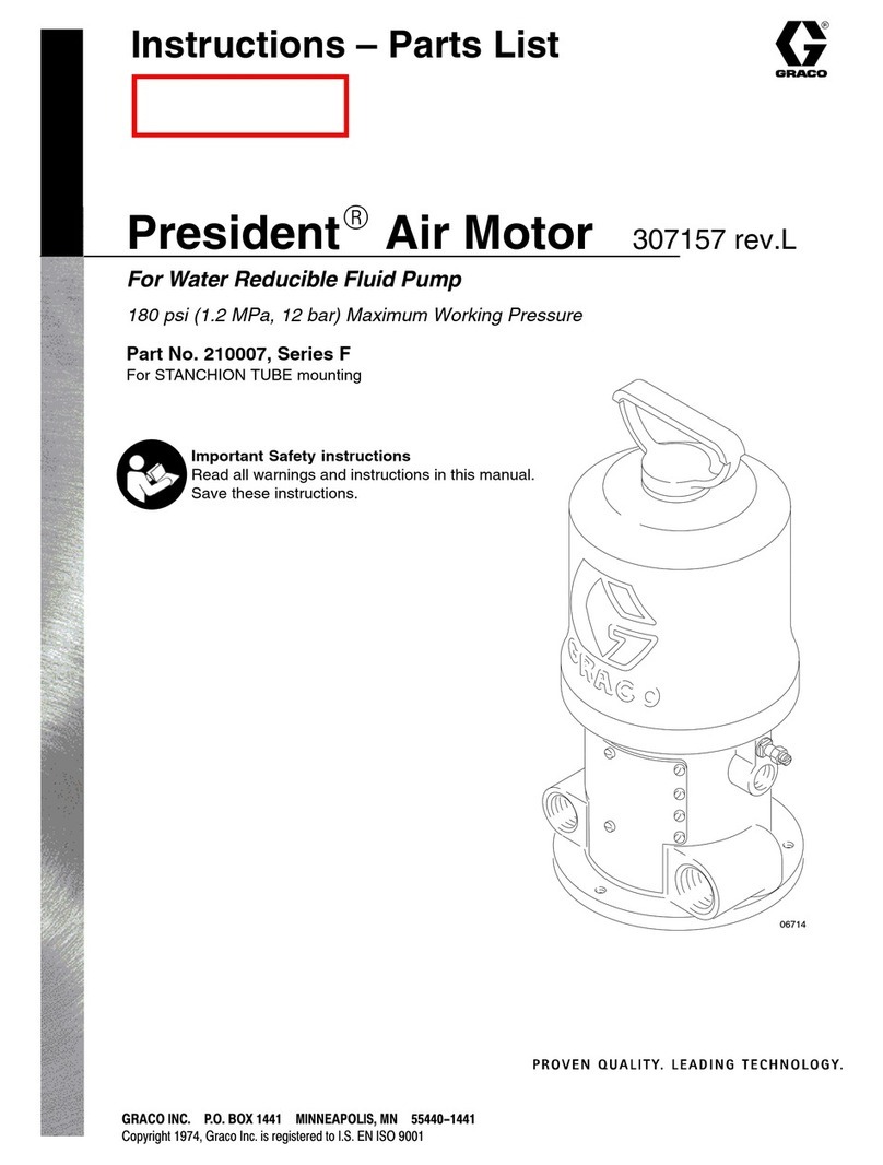
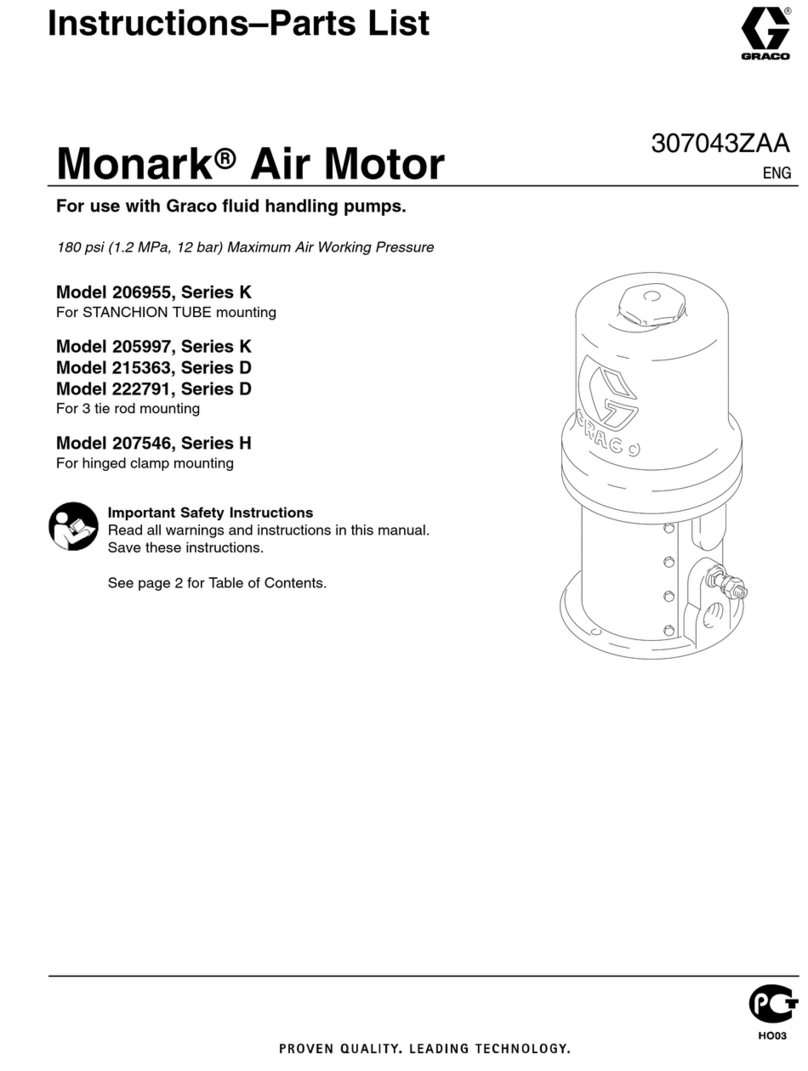
Monark
Air Motor Muffler
Model 215–354
Includes items 1–1
1
8
5, 6
3
94
1
2
E
D
JG
(See
Ref No. 7)
H
(See
Ref No. 7)
F
(See Ref No. 7)
10*
3
307–361
Install
Muffler Base
Install the muffler bases (5, 6) on the air motor with the
perforated
end flanges (D) facing the fluid outlet (E) of
the
pump.
See the
Parts Drawings. Install the screws (3) and
tighten
them evenly so the muf
fler fits tightly to the air mo
-
tor.
NOTE: Install
the screws (3) in the inside set of mounting
holes on all President muffler bases, except
President Air Motor Models 210–007 and
205–038.
Use the outside set
of mounting holes
on the muffler’s rear base on these two air mo-
tors.
Install the filter (F) on the inside of the perforated end
flange
(D). See Parts Drawings.
With pin (G) inserted in
the muffler pad (H) as shown, lay the pad in the muffler
base
(5 or 6) and snap the pin into the spring clip (J). Bend
the
clips if necessary to securely hold the pin. Repeat
for
the
other base.
Install Muffler Shields
Place the muffler shields (4) over the bases and secure
with the screws (2).
Attach
the serial plate (B) to the
shield (4) with the screws
(1).
See Fig 2.
With
the air motor operating, check all
around the muf
fler
base
for air leaks. Adjust the screws (2) if necessary
.
Fig 2
1
4
B2
PARTS
DRA
WING
REF PART DESCRIPTION QTY
NO. NO.
1 100–178 SCREW,
tapping, pnhd;
No. 6 x 0.188” long
2
2 100–264 SCREW
, mach, pnhd;
10–24 x 0.312” long
20
3 104–985 SCREW
, thd forming
16
4 176–318
SHIELD, muf
fler 2
5 218–921
BASE, muf
fler
, front
1
6 218–920
BASE, muf
fler
, rear
1
REF PART DESCRIPTION QTY
NO. NO.
7 215–374 MUFFLER PAD KIT
Includes bronze muf
fler pad,
pin, filter
2
8 181–076 GASKET
, muf
fler 2
9 176–325 GASKET
, muf
fler 2
10 176–665*
LABEL, warning; English
1
11 176–667*
LABEL, warning; Spanish, German,
French (not shown)
1
*
Extra warning labels are available at no charge.
Refer to “How to Order Parts” on the back page.
President
Air Motor Muffler
Model 214–873
Includes items 1–1
1
3
21
10*
4
9
5, 6
8
E
D
J
G
(See Ref No. 7)
H
(See Ref No. 7)
F
(See
Ref No. 7)
4307–361
HOW TO ORDER PARTS
1 To be sure you receive the correct replacement parts, kits or
accessories, always give all of the information requested in the
chart
below
.
2.
Check
the parts list
to identify the correct part number; do not use
the
ref. no. when ordering.
3.
Order all parts from your nearest Graco distributor
.
6 digit
Part Number
Qty
Part Description
SERVICE INFORMATION
The
procedure for installing the muf
fler base has been
updated.
THE
GRACO W
ARRANTY AND DISCLAIMERS
WARRANTY
Graco
warrants all equipment manufactured by it and bearing its name to be free from defects in material and workman
-
ship on the date of sale by an authorized Graco distributor to the original purchaser
for
use. As purchaser
’
s sole remedy
for
breach of this warranty
, Graco
will, for a period of twelve months from the date of sale, repair or replace any part of the
equipment proven defective. This warranty applies only when the equipment is
installed, operated and maintained in
accordance with Graco’
s written recommendations.
This
warranty does not cover
, and Graco shall not be liable for
, any malfunction, damage or wear caused by faulty
instal
-
lation,
misapplication, abrasion, corrosion, inadequate or improper maintenance, negligence, accident, tampering, or
substitution
of non–Graco component parts. Nor shall Graco be liable for malfunction, damage or wear caused by the
incompatibility with Graco equipment of
structures, accessories, equipment or materials not supplied by Graco, or the
improper
design, manufacture, installation, operation or
maintenance of structures, accessories, equipment or materi
-
als
not supplied by Graco.
This
warranty is conditioned upon the prepaid return of the equipment claimed to be defective to an authorized Graco
distributor for verification of the claim. If the claimed defect is verified, Graco will repair or replace free of charge any
defective parts. The equipment will be returned to the original purchaser transportation prepaid. If inspection of the
equipment
does not disclose any defect in material or workmanship, repairs will be made at a reasonable charge, which
charges
may include the costs of parts, labor and transportation.
DISCLAIMERS AND LIMIT
ATIONS
THE
TERMS OF THIS
W
ARRANTY CONSTITUTE PURCHASER’S SOLE AND EXCLUSIVE REMEDY AND ARE IN LIEU OF ANY OTHER W
AR-
RANTIES
(EXPRESS OR IMPLIED), INCLUDING W
ARRANTY OF MERCHANT
ABILITY OR W
ARRANTY OF FITNESS FOR A P
ARTICULAR
PUR
-
POSE,
AND OF ANY NON–CONTRACTUAL LIABILITIES, INCLUDING PRODUCT
LIABILITIES, BASED ON NEGLIGENCE OR STRICT LIABILITY
.
EVERY
FORM OF LIABILITY FOR DIRECT
, SPECIAL OR CONSEQUENTIAL DAMAGES OR LOSS IS EXPRESSL
Y EXCLUDED AND DENIED. IN
NO
CASE SHALL GRACO’S LIABILITY EXCEED THE AMOUNT OF THE PURCHASE PRICE. ANY ACTION FOR BREACH OF W
ARRANTY MUST
BE
BROUGHT WITHIN TWO (2) YEARS OF THE DA
TE OF SALE.
EQUIPMENT
NOT COVERED BY GRACO W
ARRANTY
GRACO
MAKES NO W
ARRANTY
, AND DISCLAIMS ALL IMPLIED W
ARRANTIES OF MERCHANT
ABILITY AND FITNESS FOR A P
ARTICULAR
PURPOSE,
WITH RESPECT T
O ACCESSORIES, EQUIPMENT
, MA
TERIALS, OR COMPONENTS SOLD BUT NOT MANUF
ACTURED BY GRACO.
These
items sold, but not manufactured by Graco (such as electric motor
, switches, hose, etc.) are subject to the war
-
ranty, if any, of their manufacturer. Graco will provide purchaser with reasonable assistance in making any claim for
breach
of these warranties.
Factory Branches:
Atlanta, Chicago, Dallas, Detroit, Los Angeles, W
est Caldwell (N.J.)
Subsidiary and Affiliate Companies:
Canada; England; Switzerland; France; Germany; Hong Kong; Japan
GRACO INC.
P
.O. BOX 1441
MINNEAPOLIS, MN
55440–1441
PRINTED
IN U.S.A. 307–361 9–79 Revised 9–89

This manual suits for next models

1

Other Graco Engine manuals

Graco 257570 User manual

Graco

Graco 257570 User manual

Graco Monark Operation manual

Graco

Graco Monark Operation manual

Graco E-Flo DC Series Parts list manual

Graco

Graco E-Flo DC Series Parts list manual

Graco GH200 User manual

Graco

Graco GH200 User manual

Graco 215-255 Operation manual

Graco

Graco 215-255 Operation manual

Graco XL 10000 User manual

Graco

Graco XL 10000 User manual

Graco EH 200 HDI User manual

Graco

Graco EH 200 HDI User manual

Graco President 210007 Operation manual

Graco

Graco President 210007 Operation manual

Graco Monark K Series User manual

Graco

Graco Monark K Series User manual

Graco 273199 Use and care manual

Graco

Graco 273199 Use and care manual

Graco Premier 222800 Operation manual

Graco

Graco Premier 222800 Operation manual

Graco NXT M02 Series Parts list manual

Graco

Graco NXT M02 Series Parts list manual

Graco Quiet Viscount II Operation manual

Graco

Graco Quiet Viscount II Operation manual

Graco XL 10000 Parts list manual

Graco

Graco XL 10000 Parts list manual

Graco NXT User manual

Graco

Graco NXT User manual

Graco Series A Parts list manual

Graco

Graco Series A Parts list manual

Graco BULLDOG E Series Operation manual

Graco

Graco BULLDOG E Series Operation manual

Graco Monark M Series Operation manual

Graco

Graco Monark M Series Operation manual

Graco 215-255 Operation manual

Graco

Graco 215-255 Operation manual

Graco President L Series Instruction manual

Graco

Graco President L Series Instruction manual

Graco E-Flo EM0011 Guide

Graco

Graco E-Flo EM0011 Guide

Graco E-Flo Service manual

Graco

Graco E-Flo Service manual

Graco Monark 206955 Operation manual

Graco

Graco Monark 206955 Operation manual

Graco Fast-Flo 215963 Operation manual

Graco

Graco Fast-Flo 215963 Operation manual

Popular Engine manuals by other brands

Ruggerini MD350 Use & maintenance

Ruggerini

Ruggerini MD350 Use & maintenance

Superrollo RM10MS Installation and operating instructions

Superrollo

Superrollo RM10MS Installation and operating instructions

Hatz 1B30E manual

Hatz

Hatz 1B30E manual

Rotax 125 MAX evo Installation instructions and operation manual

Rotax

Rotax 125 MAX evo Installation instructions and operation manual

Jacobsen J-125AS Service manual

Jacobsen

Jacobsen J-125AS Service manual

Evolution 1.20NX Evolution user guide

Evolution

Evolution 1.20NX Evolution user guide

Chris-Craft A-B Operator's manual

Chris-Craft

Chris-Craft A-B Operator's manual

O.S. engine FS-70S instructions

O.S. engine

O.S. engine FS-70S instructions

Bukh DV24 RME Owner's handbook

Bukh

Bukh DV24 RME Owner's handbook

SSANGYONG D20DTF Information

SSANGYONG

SSANGYONG D20DTF Information

Honeywell 46190153-501 manual

Honeywell

Honeywell 46190153-501 manual

Lycoming O-290 Operator's manual

Lycoming

Lycoming O-290 Operator's manual

Deprat TEMPO PLUS MIXTE 050TPM008 installation instructions

Deprat

Deprat TEMPO PLUS MIXTE 050TPM008 installation instructions

Yamaha F150B Service manual

Yamaha

Yamaha F150B Service manual

BRP OM-912 Operator's manual

BRP

BRP OM-912 Operator's manual

YS FZ140-2 Operator's manual

YS

YS FZ140-2 Operator's manual

Nabtesco GM Series Operation manual

Nabtesco

Nabtesco GM Series Operation manual

Yanmar 3JH5E Operation manual

Yanmar

Yanmar 3JH5E Operation manual

manuals.online logo
manuals.online logoBrands
  • About & Mission
  • Contact us
  • Privacy Policy
  • Terms and Conditions

Copyright 2025 Manuals.Online. All Rights Reserved.