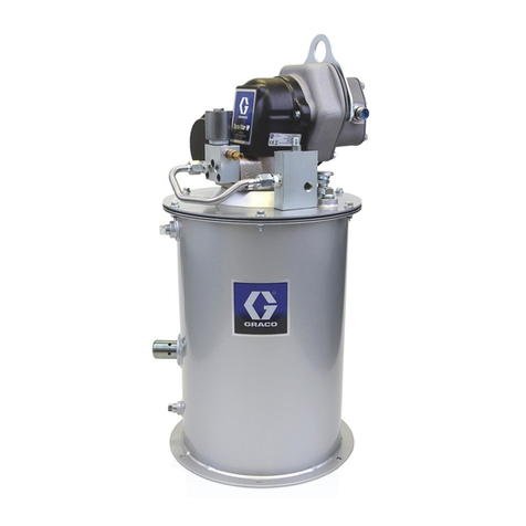
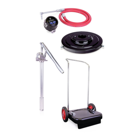
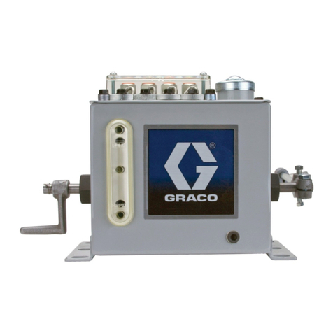
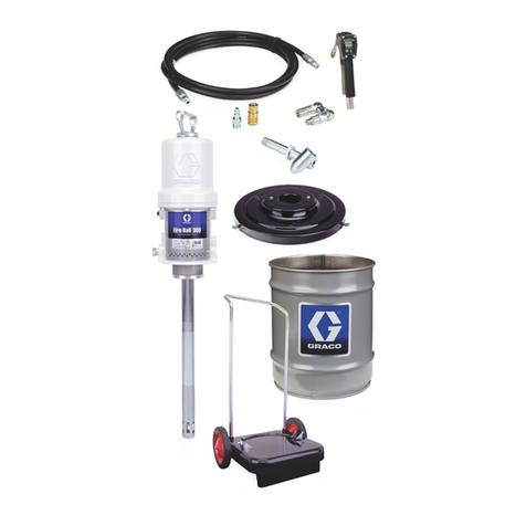
Graco Fire-Ball 425 Series User manual

306556T
EN
Instructions
Topper Units
Grease dispense units with pneumatic pump elevator for easy drum replacement. For
professional use only.
Model No. 226013
50:1 Ratio Fire-ball®Pump
5000 psi (34.5 MPa, 345 bar) Maximum Working Pressure
100 psi (0.68 MPa, 6.89 bar) Maximum Air Pressure
Model No. 226018
50:1 Ratio President®Pump
4000 psi (27.6 MPa, 276 bar) Maximum Working Pressure
80 psi (0.55 MPa, 5.5 bar) Maximum Air Pressure
Model No. 244637
75:1 Ratio President®Pump
4000 psi (27.6 MPa, 276 bar) Maximum Working Pressure
80 psi (0.55 MPa, 5.5 bar) Maximum Air Pressure
Model No. 204490
without pump or hose kit
Model No. 25P544
36:1 Ratio GT 750 Pump
3600 psi (24.8 MPa, 248.2 bar) Maximum Working Pressure
100 psi (0.68 MPa, 6.89 bar) Maximum Air Pressure
Important Safety Instructions
Read all warnings and instructions in this
manual before using the equipment. Save
these instructions.

Contents
2306556T
Contents
Warnings . . . . . . . . . . . . . . . . . . . . . . . . . . . . . . . . . . 3
Installation. . . . . . . . . . . . . . . . . . . . . . . . . . . . . . . . . 5
Grounding . . . . . . . . . . . . . . . . . . . . . . . . . . . . . . 5
Ground the Pump. . . . . . . . . . . . . . . . . . . . . . . . . 5
Pressure Relief Procedure . . . . . . . . . . . . . . . . . . 6
Typical Installation . . . . . . . . . . . . . . . . . . . . . . . . . . 7
Position the Elevator....................................... 7
Mount the Elevator .........................................8
Mount the Pump .............................................8
Secure Pump Position .................................. 10
Installation of Hoses and Valves .................. 10
Operation. . . . . . . . . . . . . . . . . . . . . . . . . . . . . . . . . 12
Installation of Drum . . . . . . . . . . . . . . . . . . . . . . 12
Removal of a Drum . . . . . . . . . . . . . . . . . . . . . . 14
Maintenance . . . . . . . . . . . . . . . . . . . . . . . . . . . . . . 15
Removal of the Pump . . . . . . . . . . . . . . . . . . . . 15
Reinstallation of the Pump . . . . . . . . . . . . . . . . . 15
End of Product Life . . . . . . . . . . . . . . . . . . . . . . . . 16
Troubleshooting . . . . . . . . . . . . . . . . . . . . . . . . . . . 17
Parts. . . . . . . . . . . . . . . . . . . . . . . . . . . . . . . . . . . . . 18
Ref No. 25: Part No. 204461
Wishbone Support Assembly ................. 23
Ref No. 91: Part No. 204467
Fire-Ball Delivery Hose Kit ..................... 24
Ref No. 97: Part No. 205102
President Delivery Hose Kit ................... 24
Ref No. 112: Part No. 25P547
GT 750 36:1 Pump Mounting Kit............ 24
Dimensions . . . . . . . . . . . . . . . . . . . . . . . . . . . . . . . 25
Technical Specifications . . . . . . . . . . . . . . . . . . . . 26
California Proposition 65 . . . . . . . . . . . . . . . . . . 27
Graco Standard Warranty . . . . . . . . . . . . . . . . . . . 28

Warnings
306556T 3
Warnings
The following warnings are for the setup, use, grounding, maintenance, and repair of this equipment. The
exclamation point symbol alerts you to a general warning and the hazard symbols refer to procedure-specific risks.
When these symbols appear in the body of this manual or on warning labels, refer back to these Warnings.
Product-specific hazard symbols and warnings not covered in this section may appear throughout the body of this
manual where applicable.
WARNING
SKIN INJECTION HAZARD
High-pressure fluid from dispensing device, hose leaks, or ruptured components will pierce skin. This
may look like just a cut, but it is a serious injury that can result in amputation. Get immediate surgical
treatment.
• Do not point dispensing device at anyone or at any part of the body.
• Do not put your hand over the fluid outlet.
• Do not stop or deflect leaks with your hand, body, glove, or rag.
• Follow the Pressure Relief Procedure when you stop dispensing and before cleaning, checking, or
servicing equipment.
• Tighten all fluid connections before operating the equipment.
• Check hoses and couplings daily. Replace worn or damaged parts immediately
FIRE AND EXPLOSION HAZARD
When flammable fluids are present in the work area, such as gasoline and windshield wiper fluid, be
aware that flammable fumes can ignite or explode. To help prevent fire and explosion:
• Use equipment only in well-ventilated area.
• Eliminate all ignition sources, such as cigarettes and portable electric lamps.
• Ground all equipment in the work area.
• Keep work area free of debris, including rags and spilled or open containers of solvent and gasoline.
• Do not plug or unplug power cords or turn lights on or off when flammable fumes are present.
• Use only grounded hoses.
•Stop operation immediately if static sparking occurs or you feel a shock.Do not use equipment until
you identify and correct the problem.
• Keep a working fire extinguisher in the work area.

Warnings
4306556T
EQUIPMENT MISUSE HAZARD
Misuse can cause death or serious injury.
• Do not operate the unit when fatigued or under the influence of drugs or alcohol.
• Do not exceed the maximum working pressure or temperature rating of the lowest rated system
component. See Technical Specifications in all equipment manuals.
• Use fluids and solvents that are compatible with equipment wetted parts. See Technical
Specifications in all equipment manuals. Read fluid and solvent manufacturer’s warnings. For
complete information about your material, request Safety Data Sheets (SDSs) from distributor or
retailer.
• Turn off all equipment and follow the Pressure Relief Procedure when equipment is not in use.
• Check equipment daily. Repair or replace worn or damaged parts immediately with genuine
manufacturer’s replacement parts only.
• Do not alter or modify equipment. Alterations or modifications may void agency approvals and create
safety hazards.
• Make sure all equipment is rated and approved for the environment in which you are using it.
• Use equipment only for its intended purpose. Call your distributor for information.
• Route hoses and cables away from traffic areas, sharp edges, moving parts, and hot surfaces.
• Do not kink or over bend hoses or use hoses to pull equipment.
• Keep children and animals away from work area.
• Comply with all applicable safety regulations.
MOVING PARTS HAZARD
Moving parts can pinch, cut or amputate fingers and other body parts.
• Keep clear of moving parts.
• Do not operate equipment with protective guards or covers removed.
• Equipment can start without warning. Before checking, moving, or servicing equipment, follow the
Pressure Relief Procedure and disconnect all power sources.
TOXIC FLUID OR FUMES HAZARD
Toxic fluids or fumes can cause serious injury or death if splashed in the eyes or on skin, inhaled, or
swallowed.
• Read Safety Data Sheets (SDSs) to know the specific hazards of the fluids you are using.
• Store hazardous fluid in approved containers, and dispose of it according to applicable guidelines.
PERSONAL PROTECTIVE EQUIPMENT
Wear appropriate protective equipment when in the work area to help prevent serious injury, including
eye injury, hearing loss, inhalation of toxic fumes, and burns. Protective equipment includes but is not
limited to:
• Protective eyewear, and hearing protection.
• Respirators, protective clothing, and gloves as recommended by the fluid and solvent manufacturer.
WARNING

Installation
306556T 5
Installation
Grounding
Pump: use ground wire and clamp, as shown in FIG. 1.
Air and fluid hoses: use only electrically conductive
hoses.
Air compressor: follow manufacturer’s
recommendations.
Dispense valve: ground through connection to a
properly grounded fluid hose and pump.
Fluid supply container: follow local code.
Truck bed or platform: follow local code.
Solvent pails used when flushing: follow local code.
Use only conductive metal pails, placed on a grounded
surface. Do not place the pail on a nonconductive
surface, such as paper or cardboard, which interrupts
grounding continuity.
To maintain grounding continuity when flushing or
relieving pressure: hold metal part of the spray
gun/dispense valve firmly to the side of a grounded
metal pail, then trigger the gun/valve.
Ground the Pump
1. Remove the ground screw (Z) and insert through
the eye of the ring terminal at the end of ground wire
(Graco P/N 238909, user supplied) (Y), see FIG. 1.
2. Fasten the ground screw back into the pump and
tighten securely.
3. Connect the other end of the ground wire to a true
earth ground (FIG. 1).
The equipment must be grounded to reduce the risk
of static sparking. Static sparking can cause fumes to
ignite or explode. Grounding provides an escape wire
for the electric current.
FIG. 1
Z
Y
Supply Pump

Installation
6306556T
Pressure Relief Procedure
Follow the Pressure Relief Procedure whenever
you see this symbol.
1. Close the supply pump’s bleed-type master air valve
(required in this system) (FIG. 2).
2. Open the air supply ball valve (FIG. 2). The handle
will be in line with the valve body.
3. Hold a metal part of the grease dispensing valve
firmly to a grounded metal waste container and
open the dispensing valve until the pressure is fully
relieved.
4. If you suspect the dispense valve tip or hose is
clogged, or that pressure has not been fully relieved:
a. VERY SLOWLY loosen the hose end coupling to
relieve pressure gradually.
b. Loosen the nut or the coupling completely.
c. Clear the obstruction in the hose or dispense
valve tip.
This equipment stays pressurized until pressure is
manually relieved. To help prevent serious injury from
pressurized fluid, such as skin injection, splashing
fluid and moving parts, follow the Pressure Relief
Procedure when you stop dispensing and before
cleaning, checking, or servicing the equipment.

Typical Installation
306556T 7
Typical Installation
The Typical Installation (shown in FIG. 2), is only a guide
for selecting and installing this system. It is not an actual
system design.
Position the Elevator
1. Position the elevator in an area where the ceiling is
at least 8 ft. (2.6 m) in height. The elevator when
fully extended is 90 in (2.4 m).
2. Provide adequate space in front of the elevator for
changing drums.
3. Provide adequate space along the sides and back
of the elevator for plumbing.
FIG. 2: Typical Installation
mounting
holes
5’(1524 mm)
supply line
s
(through wall)
bleed-type
master air valve
high pressure
fluid shutoff valve
supply lines
(from ceiling)
3” (76 mm)
1” (25 mm)
6” (152.4 mm)
clearance
for plumbing
supply pump
(required)
air supply ball valve

Typical Installation
8306556T
Mount the Elevator
1. Secure the elevator base (A) to the mounting base
(102) using screws (104), lock washers (103), and
nuts (105) (FIG. 3).
2. Bolt the mounting base (102) to the floor, using the
four predrilled mounting holes for stability (FIG. 3).
3. Verify that the elevator is level. If not, loosen one or
two of the screws (104) on the elevator base (A) and
place shims underneath the base until level.
4. Place the inductor plate (2, 18, 22 or 116) on the
mounting base (102) (FIG. 3).
5. Loosen the screws (68) of both support brackets
(83).
6. Slide the support (64) down to allow installation of
the pump into the inductor plate.
7. Tighten the bracket screws (68) lightly.
Mount the Pump
Models 226013, 226018, 244637
1. Position the pump mounting bracket (86) then
tighten the set screws to secure in place (FIG. 4).
2. Remove the inductor plate nut (11, 24 or 114), the
locking ring (8, 23 or 115) and the o-ring (9) (FIG. 5).
3. Using this order, slide the inductor plate nut (11, 24
or 114), the locking ring (8, 23 or 115), and the
o-ring (9) on the pump riser tube (FIG. 5).
4. Loosen the pump support brackets (83) and raise
the support (64) until it meets the pump base (FIG.
8).
FIG. 3:
A
102
103
104
105
18
FIG. 4:
FIG. 5:
86
68
64
Pump Intake Slots
Pump Riser Tube
11, 24, or 114
2, 22, or 116
8, 23, or 115

Typical Installation
306556T 9
5. Secure the pump to the pump mounting brackets
(86) from the underside with screws (68).
6. Adjust the inductor plate on the pump so the pump
intake slots are located just below the bottom of the
inductor plate cone (see FIG. 5).
7. Tighten the lock nut (11, 24 or 114) securely.
Model 204490
Refer to FIG. 6 for Steps 1-3, below.
1. Lubricate the o-ring (20) in the inductor plate (18)
with light, waterproof grease.
2. Guide the pump intake valve as far as possible into
the inductor plate, then tighten the set screws (19).
4. Loosen the pump support brackets (83) and raise
the support (64) until it meets the pump base.
5. Secure the pump to the pump support mounting
bracket (86) from the underside with screws (68).
Model 25P544
Refer to FIG. 5 and FIG. 7 for Steps 1-6 below.
1. Position the pump mounting brackets (86), then
tighten the set screws to secure in place.
2. Mount the bung adapter plate (117) to the pump
mounting brackets (86) using cap hex screws (118).
3. Remove the inductor plate nut (114), ferrule (115)
and the o-ring (113) (FIG. 5).
4. Lower the pump tube through the bung adapter
plate (117).
5. Using this order, slide the inductor plate nut (114),
ferrule (115), and the o-ring (113) on the pump riser
tube (FIG. 5).
6. Adjust the inductor plate on the pump so that the
pump intake slots are located just below the bottom
of the inductor plate cone (see FIG. 5).
7. Tighten the lock nut (114) securely.
8. Loosed the pump support clamps and raise the
support (64) until the bung adapter plate (117)
meets the bung adapter on the pump tube.
9. Turn the bung adapter into the bung adapter plate
until tight.
FIG. 6:
18
20 19
FIG. 7:
117
86
bung
adapter

Typical Installation
10 306556T
Secure Pump Position
Refer to FIG. 5 and FIG. 8 for the following steps.
1. Adjust the pump height by sliding the pump support
(64) up or down, until the pump intake is 0.12 in.
(3.2 mm) above the mounting base (102, FIG. 3).
2. Tighten the screws (68) on the lower pump bracket
(83).
3. Slide the upper pump support bracket (83) up or
down (the pump support (64) tubing flexes slightly)
until the pump is in a true vertical position.
4. Tighten the screws (68) on the upper pump bracket.
Installation of Hoses and Valves
NOTE: Use thread sealant on all male threads except at
the swivel unions.
Refer to FIG. 9 and FIG. 17 for the following steps.
1. Remove the plug from the top of the elevator cap
and screw it into the air inlet (E) in the elevator base
(FIG. 9).
2. Screw the restrictor valve assembly (42) into the
elevator cap.
3. Screw the 1/4 x 1/8 npt adapter (85) into the
restrictor valve (FIG. 9).
4. Install the 1/4 x 3/8 npt adapter (89) (FIG. 9).
5. Connect one end of the 36 in. (914 mm) hose into
the adapter and connect the other end of the hose
into the elevator valve’s (27) union (82) (FIG. 9).
6. Route the hose inside the arms of the pump support
(64) (FIG. 8).
7. Install user-supplied bleed-type master air valve into
the pump’s air supply line.
FIG. 8:
68
83
64
The bleed-type master air valve is required in the
system to relieve air trapped between this valve and
the pump after the air is shut off. Trapped air can
cause the pump to cycle unexpectedly and cause
serious injury, including amputation and skin injection.
Position the valve close to the pump.
FIG. 9:
85
27
89
E
Elevator Cap
42

Typical Installation
306556T 11
Models 226013,226018, 244637, 204490
8. Attach the hex nipple (115 or 99) from the outlet
hose kit (91 or 97) to the pump outlet. (See Parts,
page 18).
9. Connect the kit’s swivel union (96) to the adapter
with the opening in the valve (94) facing downward.
(See Parts, page 18).
10. Install a user-supplied pressure rated fluid shutoff
valve (not required) on the fluid supply line to control
the flow of fluid from the pump.
11. Finish assembling the hoses and fittings, as shown
on Parts, page 18.
Model 25P544
8. Install user-supplied pressure rated fluid outlet hose
to pump outlet.
9. Install a user-supplied pressure rated fluid shutoff
valve (not required) on the fluid supply line to control
the flow of fluid from the pump.
10. Finish assembling the hoses and fittings, as shown
on Parts, page 18.

Operation
12 306556T
Operation
I
Installation of Drum
Refer to FIG. 10 for the following instructions.
1. Perform Pressure Relief Procedure, page 6.
2. Close the ball valve (65). When closed, the handle
will be at a 90° angle to the valve body.
3. Open the bleed-type master air valve (F).
4. Open the inductor plate vent by turning the knob
(10) counter-clockwise.
5. Pull open the elevator valve (27) to raise the
elevator.
NOTE: To adjust the elevator speed, loosen the jam nut
(43). Turn the restrictor valve screw (46) clockwise to
decrease speed, counter-clockwise to increase speed.
Tighten the jam nut once the desired speed has been
set.
6. Center an opened 400 lb. (181.4 kg) drum under the
inductor plate so that the drum bottom touches the
elevator base (A).
7. Make the top of the fluid concave by scooping fluid
from the center to the sides of the container.
8. Loosen the setscrews (73) holding the pump
mounting brackets (86) to the support (64). Align the
pump and inductor plate with the drum.
NOTICE
Always close the ball valve (65) when the inductor
plate reaches the bottom of the drum, indicating the
drum is empty. Allowing the pump to run without fluid
will damage the pump.
FIG. 10:
27
73
10
D
F43
65
A
64
94
47
46
86

Operation
306556T 13
9. Push in the elevator valve (27) to lower the pump
while guiding the inductor plate into the drum.
10. Press down on the pump, rocking it back and forth,
to seat the inductor plate. This helps eliminate any
air trapped underneath the plate. Continue this
action until fluid appears at the vent opening (D).
11. Verify that the pump is aligned vertically, then
tighten the set screws (73).
12. Close the inductor plate vent by turning the knob
(10) clockwise.
13. For Models 226013, 226018, and 244637 only:
a. Open the bleeder valve (94) at the pump outlet
by turning the thumbscrews counter-clockwise.
b. Open the ball valve (65) until all of the air
trapped in the pump, and under the plate, is
pumped through the bleeder valve.
c. Close the ball valve (65) and the bleeder valve
(94).
d. Regulate the pump speed with the ball valve
(65) handle.
14. For all Models: Always use the lowest possible
pump pressure necessary for good delivery. Higher
pressures causes premature pump wear and
usually do not produce better results.
Moving Parts Hazard
Keep fingers and hands away from the sides of the
drum and the inductor plate to avoid pinching when
raising and lowering the pump.

Operation
14 306556T
Removal of a Drum
1. Perform Pressure Relief Procedure, page 6
2. Close the ball valve (65). When closed, the handle
will be at a 90° angle to the valve body.
3. Open the bleed-type master air valve (F).
4. Press in and hold the air-assist valve (47) until the
inductor plate rises above the drum. Release the
valve (FIG. 10, page 12).
5. Open the elevator valve (27) then raise the elevator
to full height (FIG. 10, page 12).
NOTE: If air pressure is lost when reaching the drum
ribs, continue holding the air-assist valve and slowly pull
out the elevator valve until the ribs are passed. Then,
immediately close the elevator valve to prevent raising
the drum off of the floor.
6. Remove the drum.
7. Move a new drum into position and install (see
Installation of Drum, page 12).
NOTE: Lower the pump completely if not immediately
installing a new drum.
Foot Crush Hazard
Using the elevator valve before the inductor plate is
out of the drum can lift the drum, creating a potential
foot crush hazard.
Use only the air-assist valve to make the inductor
plate rise to the top of the drum.

Maintenance
306556T 15
Maintenance
Refer to FIG. 11 for reference numbers.
NOTE: To avoid contaminating the fluid in the supply
container, keep the pump intake an the inductor plate
clean during servicing operations. Place the parts on
clean paper or rags.
Removal of the Pump
1. Remove the drum (see Removal of a Drum. page
14).
2. Relieve the pressure. See Pressure Relief
Procedure, page 6.
3. Disconnect the air-assist hose (41).
For Model 204490: Loosen the inductor plate set
screws (19).
For Models 226013, 226018, and 244637:
Unscrew the locking nut (11, 24, or 114), taking note
of the number of turns needed.
4. Disconnect and remove the pump from the
mounting bracket.
Reinstallation of the Pump
1. Connect the pump to the mounting bracket.
2. Attach the hoses to the pump.
3. Pull the elevator valve (27) to raise the pump.
4. Attach the drum. See Installation of Drum, page
12.
NOTE: When attaching the pump to the inductor plate,
turn the locking nut (11, 24, or 114) the same number of
turns as noted in Removal of the Pump, Step 3, or until
the inductor plate is settled.
FIG. 11:
41 27
89

End of Product Life
16 306556T
End of Product Life
At the end of the product’s useful life, dismantle and
recycle it in a responsible manner.
• Perform the Pressure Relief Procedure, page 6.
• Drain and dispose of fluids according to applicable
regulations. Refer to the material manufacturer’s
Safety Data Sheet.
• Deliver remaining product to a recycling facility.

Troubleshooting
306556T 17
Troubleshooting
1. Follow Pressure Relief Procedure, page 6, before
checking or repairing the pump.
2. Check all possible problems and causes before
disassembling pump.
Problem Cause Solution
Low flow or air is being sucked into
pump under the inductor plate.
Open inductor plate vent. Close the inductor plate.
Inductor plate sleeve locking nuts
are loose.
Tighten the locking nuts.
Worn inductor seals. Replace the seals. See Parts, page
18.
Failure of snap-valve or air-assist
valve.
Worn o-rings or seals Remove valve, place in vise,
disassemble and replace parts as
needed.

Parts
18 306556T
Parts
Model 204490
Elevator and Inductor Plate Assembly
Includes items 17, 25, 90, and 101
Model 226013
Pump, Elevator, and Inductor Plate Assembly
Includes items 1, 25, 89, 90, 91 and 101
Model 226018
Pump, Elevator, and Inductor Plate Assembly
Includes items 21, 25, 90, 97, 101, and 106
Model 244637
Pump, Elevator, and Inductor Plate Assembly
Includes items 21, 25, 90, 97, 101, and 107
Model 25P544
Pump, Elevator, and Inductor Plate Assembly
Includes items 25, 90, 101, 108, 109, 112
Ref
No.
Parts
No. Description Qty.
17 204405 INDUCTOR PLATE ASSEMBLY
See parts on page 19
1
25 204461 WISHBONE SUPPORT ASSEMBLY
See parts on page 22
1
90 204385 PNEUMATIC ELEVATOR
See manual 306287 for parts
1
101 205339 ELEVATOR BASE
See parts on page 19
1
Ref
No. Part No. Description Qty.
1 204353 INDUCTOR PLATE ASSEMBLY
See parts on page 19
1
25 204461 WISHBONE SUPPORT ASSEMBLY
See parts on page 22
1
89 239888 50:1 RATIO FIRE-BALL PUMP
See manual 308883 for parts
1
90 204385 PNEUMATIC ELEVATOR
See manual 306287 for parts
1
91 204467 HOSE KIT
See parts on page 24
1
101 205339 ELEVATOR BASE
See parts on page 19
1
Ref
No. Part No. Description Qty.
21 205699 INDUCTOR PLATE ASSEMBLY
See parts on page 19
1
25 204461 WISHBONE SUPPORT ASSEM-
BLY
See parts on page 22
1
90 204385 PNEUMATIC ELEVATOR
See manual 306287 for parts
1
97 205102 HOSE KIT
See parts on page 24
1
101 205339 ELEVATOR BASE
See parts on page 19
1
106 205395 50:1 RATIO PRESIDENT PUMP
See manual 306674 for parts
1
Ref
No. Part No. Description Qty.
21 205669 INDUCTOR PLATE ASSEMBLY
See parts on Page 19
1
25 204461 WISHBONE SUPPORT ASSEMBLY
See parts on page 22
1
90 204385 PNEUMATIC ELEVATOR
See manual 306287 for parts
1
97 205102 HOSE KIT
See parts on page 24
1
101 205339 ELEVATOR BASE
See parts on page 19
1
107 239730 75:1 RATIO PRESIDENT PUMP
See manual 308777 for parts
1
Ref
No. Part No. Description Qty.
25 204461 WISHBONE SUPPORT ASSEMBLY
See parts on page 22
1
90 204385 PNEUMATIC ELEVATOR
See manual 306287 for parts
1
101 205339 ELEVATOR BASE
See parts on page 19
1
108 24W337 36:1 RATIO GT 750 PUMP
See manual 3A5363 for parts
1
109 25P545 INDUCTOR PLATE ASSEMBLY
See parts on Page 19
1
112 25P547 MOUNTING KIT
See parts on Page 24
1

Parts
306556T 19
Ref No. 101: Part No. 205339
Elevator Base Assembly
Includes items 102 - 105
Ref
No. Part No. Description Qty.
102 205340 BASE, elevator 1
103 100018 LOCKWASHERS, spring, 1/2 in. 4
104 100096 SCREW, hex hd cap, 1/2-13 x 2 in. 4
105 100321 NUT, 1/2-13 4
FIG. 12:
90
89, 106, 107, or 108
91 or 97
103
104
105
102
1, 17, 21, or 109

Parts
20 306556T
Ref No. 1: Part No. 204353
Inductor Plate Assembly: 400 lb Drum size
Fits 50:1 Fire-Ball In-Line Pump;
Includes items 2-16
Ref No. 17: Part No. 204405
Inductor Plate Assembly: 400 lb Drum size
Fits Monarch and President In-Line Pumps
Includes items 3 - 7, 10, 12 - 16, 18 - 20
Ref
No. Part No. Description Qty.
2 204502 PLATE, inductor, bare 1
3 100015 NUT, hex, mscr, 1/4-20 UNC-2a 1
4 100021 CAPSCREW, hex hd, 1/4-20 UNC-2a
x 1 in. 1
5 104663 PLUG, pipe, 3/4 npt (f) 1
6 100799 SCREW, mach, rd hd, 1/4-20 x 1/2 in. 18
7 100859 SCREW, headless, full dog point, No.
10-24 x 1/4 in. 1
8 101644 SLEEVE, coupling 1
9 158776 O-RING 1
10 160865 KNOB, vent 1
11 161107 NUT, locking 1
12 161162 SEAL, rubber 1
13 161287 WIPER, inductor plate 1
14 161288 SEGMENT, full barrel 6
15 164432 CAP, vent 1
16 164497 ROD, vent release 1
FIG. 13:
6
14
4
10
3
16
15
7
12
2
13
5
9
8
11
Tapered
shoulder
facesup
Ref No. 1
Ref
No. Part No. Description Qty.
3 100015 NUT, hex, mscr, 1/4-20 UNC-2a 1
4 100021 CAPSCREW, hex hd, 1/4-20 UNC-2a
x 1 in.
1
5 104663 PLUG, pipe, 3/4 npt (f) 1
6 100799 SCREW, mach, rd hd, 1/4-20 x 1/2 in. 18
7 100859 SCREW, headless, full dog point, No.
10-24 x 1/4 in.
1
10 160865 KNOB, vent 1
12 161162 SEAL, rubber 1
13 161287 WIPER, inductor plate 1
14 161288 SEGMENT, full barrel 6
15 164432 CAP, vent 1
16 164497 ROD, vent release 1
18 204507 PLATE, inductor, bare 1
19 100556 SETSCREW, sq hd cup point,
5/16-18 x 3/8 in.
2
20 160721 O-RING, nitrile rubber 1
FIG. 14:
6
14
4
10
3
16
15
7
12
19
20
5
18
13
Ref No. 17
This manual suits for next models
6
Table of contents
Other Graco Lubrication System manuals

Graco
Graco 203-697 E Series Operation manual

Graco
Graco GREASE JOCKEY User manual

Graco
Graco FIRE-BALL Series Operation manual

Graco
Graco Manzel HP-50 Guide

Graco
Graco FIRE-BALL Operation manual

Graco
Graco Mini Fire-Ball 225 Series Operation manual

Graco
Graco Spindl-Gard 24B219 User manual

Graco
Graco Progressive Series User manual

Graco
Graco 309015B Guide

Graco
Graco FIRE–BALL 300 Air Motor Muffler Kit Operation manual