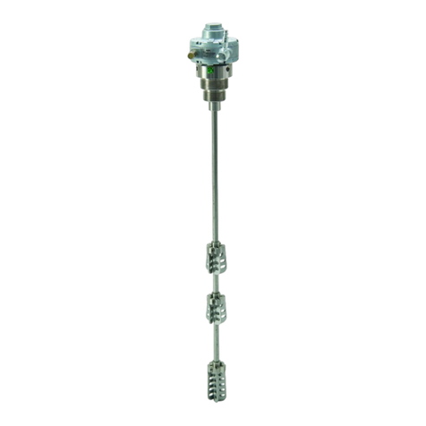
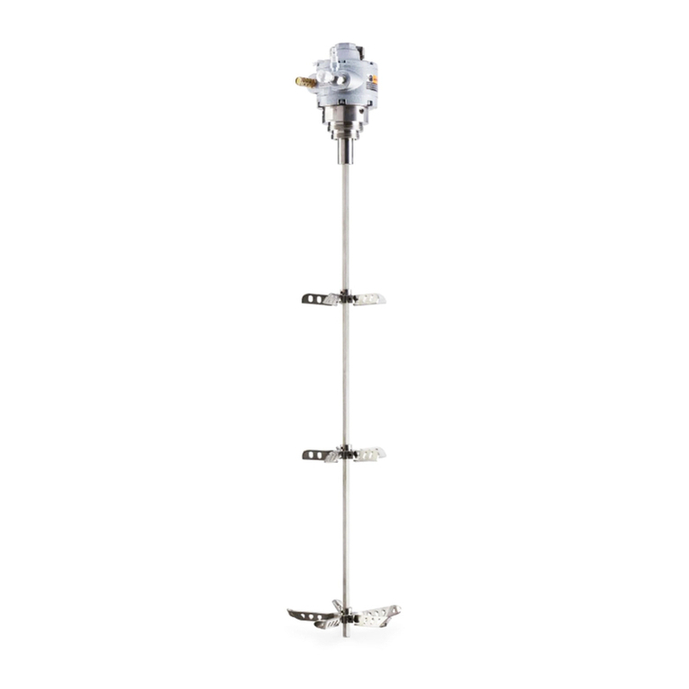
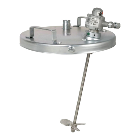
Graco Twistork A Series Operation manual

INSTRUCTIONS–P
ARTS LIST
308–246
Rev. B
Supersedes Rev A
This
manual contains IMPORT
ANT
W
ARNINGS AND INSTRUCTIONS
READ AND RET
AIN FOR REFERENCE
AIR DRIVEN
Twistork
HELIX MIXER
100
psi (7 bar) MAXIMUM WORKING AIR PRESSURE
Model
235–653, Series A
Stainless Steel Agitator, with suction feature
For use in bung-mounted 55 gallon drum
GRACO INC. P.O. BOX 1441 MINNEAPOLIS, MN 55440–1441
COPYRIGHT 1992 GRACO INC.
TABLE OF CONTENTS
Warnings 2.
. . . . . . . . . . . . . . . . . . . . . . . . . . . . . . . . . . . .
Installation 3
. . . . . . . . . . . . . . . . . . . . . . . . . . . . . . . . . . .
Operation & Maintenance 4.
. . . . . . . . . . . . . . . . . . . . .
Accessories 5
. . . . . . . . . . . . . . . . . . . . . . . . . . . . . . . . . .
Parts
Drawing
6.
. . . . . . . . . . . . . . . . . . . . . . . . . . . . . . . .
Parts List 7.
. . . . . . . . . . . . . . . . . . . . . . . . . . . . . . . . . . . .
Dimensional
Drawing
7.
. . . . . . . . . . . . . . . . . . . . . . . . .
Technical
Data
Back Cover
.
. . . . . . . . . . . . . . . . . . . . . .
Graco
Phone Numbers
Back Cover
.
. . . . . . . . . . . . . .
Warranty Back
Cover
.
. . . . . . . . . . . . . . . . . . . . . . . . . . .
0910A
Patented
in the United States and Europe

SAFETY
W
ARNINGS
FOR PROFESSIONAL USE ONLY. OBSERVE ALL WARNINGS
Read and understand all instruction manuals before operating equipment.
EQUIPMENT MISUSE HAZARD
General Safety
Any misuse of the equipment or accessories, such as
overpressurizing, modifying parts, using incompatible
chemicals and fluids, or using worn or damaged parts,
can
cause them to rupture and result in
serious bodily in
-
jury, including splashing in the eyes or on the skin, fire,
explosion
or property damage.
NEVER
alter or modify any part of this equipment; doing
so
could cause it to malfunction and make it dangerous to
operate.
CHECK all spray equipment regularly and repair or
replace
worn or damaged parts immediately
.
System Pressure
The
MAXIMUM WORKING PRESSURE
of the agitator
is 100 psi (7 bar). Over-pressurizing the agitator or ac-
cessories could cause a part to rupture. To reduce the
risk of serious bodily injury, including splashing in the
eyes or on the skin, and property damage, NEVER ex-
ceed
the maximum air and fluid working pressure of any
component
or accessory used in the system.
Fluid Compatibility
BE SURE all fluids and solvents used are chemically
compatible
with the “W
etted Parts” shown in the
TECH-
NICAL DATA on the back page. Always read the fluid
and solvent manufacturer’s literature before using the
fluid
or solvent with this agitator
.
FIRE OR EXPLOSION HAZARD
All electrically conductive objects or devices
in the
spray
area MUST be properly grounded.
When operating the system, any ungrounded objects in
the spray area can become electrically charged. Arcing
may
occur if these objects then come in
contact or close
to
ground. Arcing of suf
ficient
energy levels can ignite the
fluid
being sprayed, fumes from
solvents, dust particles,
and
other
flammable substances. This can cause a fire,
explosion, or electrostatic shock and result in serious
bodily
injury and property damage.
To
ground the agitator
,
remove
the grounding screw
(A) and lockwasher (B). See Fig 1. Secure the ground
wire
terminal (C) to the agitator
with the screw and lock
-
washer. Connect the other end of the ground wire to a
true
earth ground. See page
ACCESSORIES
to order a
ground
wire and clamp.
01089
Fig 1
A
B
C
MOVING
P
ARTS HAZARD
The rotating helix of the agitator can pinch or amputate
your
fingers or other body parts and can cause splashing
in
the eyes or on the skin. T
o reduce this risk, always shut
off
the agitator and disconnect
the air line before check
-
ing
or repairing any part of the agitator
.
IMPORTANT
United States Government safety standards have been
adopted under the Occupational Safety and Health Act.
These standards – particularly the General Standards,
Part
1910, and the Construction Standards, Part 1926
–
should
be consulted.

INSTALLATION
Air Requirements
For
continuous use, the 1/2 HP agitator air motor typically
requires
2 scfm (0.06 m
/min.) of air at 400 rpm and with
100
psi (7 bar) inlet pressure.
Air Line Accessories
Install
an air line filter to remove harmful dirt and
moisture
from
the air supply
. See
ACCESSORIES.
Downstream
from the filter
, install an air line lubricator for
automatic air motor lubrication. Set the lubricator feed
rate
at 1 to 3 drops per hour
.
Installing the Agitator
1. If
using the agitator suction feature,
remove the fluid
tube plug (7) at the bottom of the agitator, before
installing
it into the drum. See
P
ARTS DRA
WING.
NOTE: If there is a thick sediment in the bottom of the
fluid
container that could clog the agitator
’
s fluid
tube,
thoroughly mix the fluid with the plug (7) still
in
place in the agitator before removing it to use
the
suction feature.
2. Install the agitator on the container cover by screw-
ing
the helix through the drum bung hole and screw
-
ing
the agitator housing into the bung hole. Refer to
the
DIMENSION DRA
WING.
3. Position the air motor so the air line can easily be
attached
to the needle valve’
s 1/8 npt inlet (B), with
-
out obstructing any other system components. See
Fig 2.
4. Attach
the air line between the
needle valve’
s 1/8 npt
air
inlet and the 1/8 npt air supply manifold outlet.
5. If using the agitator suction feature, connect a fluid
line
to the 3/4–14 npt(f) agitator fluid outlet (A).
Fig 2
11
12
0910A
A
1a
KEY
AFluid
Outlet
B
1/8 npt Air Inlet
1a Muffler
11
Needle V
alve
12 Check Valve
B

OPERATION & MAINTENANCE
WARNING
To
reduce the risk of serious bodily injury
, including
cuts, amputation of fingers, and splashing in the
eyes
or on the skin, always shut of
f the agitator and
disconnect the air line before checking or repairing
the
agitator
.
Operating the Agitator
NOTE: If there is a thick sediment in the bottom of the
fluid
container that could clog the agitator
’
s fluid
tube,
thoroughly mix the fluid with the plug (7) still
in
place in the agitator before removing it to use
the
suction feature. Refer to
the
P
ARTS DRA
W-
ING.
1. Fill
the fluid supply container
.
2.
Start the agitator
.
3. Use
the agitator needle valve to regulate the
agitator
speed.
The needle valve
has numbered graduations
to
refer to when setting the agitator speed.
NOTE:
If an air shut-off valve is installed in the supply
line
and used to stop the agitator
, the same agita
-
tor speed will be set each time the agitator is
used without repeating the above procedure.
See
ACCESSORIES.
CAUTION
DO
NOT
operate the agitator at a high speed for a
long
period of time. Excessive agitator speed can
cause
foaming of fluid (making the fluid unusable),
vibration,
and increased wear on
parts. Always ag
-
itate
the fluid only enough to maintain even
mixing.
4. Operate the agitator continuously while supplying
paints
or other fluids to the system.
5. To
stop the agitator
, close the air valve in the air sup
-
ply
line if you have one, or close the agitator needle
valve.
NOTE: The
agitator rotation may be reversed by switch
-
ing
the muf
fler (1a) and needle valve (1
1). Refer
to
Fig 2.
Checking Fluid Viscosity
Install
a fitting and siphon tube (not provided) into the
agi
-
tator’s 3/4 npt(f) fluid outlet (A). Refer to Fig 2. With the
siphon tube routed to a separate container, pump the
fluid
out through the agitator outlet port to check viscosity
.
Maintaining the Agitator Air Motor
If
an air line lubricator is not installed, the air motor must
be
manually lubricated every 8 hours. Lubricate the agi
-
tator
air motor by placing 2 or 3 drops of SAE No. 10 light
oil in the motor’s air inlet. Run the agitator for about 30
seconds.
The
air check valve
(12) allows make-up air to enter the
closed
drum as fluid is drawn out through the agitator
out
-
let
port. Refer to Fig 2. The air
check valve should be in
-
spected
and cleaned periodically
.
If the air motor operation is erratic or sluggish, flush the
motor
as follows:
1. Remove the needle valve and fill the air inlet cavity
with
kerosene. Screw the needle valve
back in. See
Fig
2.
2. Soak for about 10 minutes, then run the agitator
slowly
until all
the kerosene is blown out. Repeat the
process
if the motor still doesn’t run smoothly
.
WARNING
To reduce risk of serious bodily injury, including
splashing
kerosene in the eyes or on
skin, keep face
and
body away from exhaust while flushing.
NOTE: An Air Motor Repair Kit is available. Order part
number
224–954.
Aligning the Outlet Housing after Repairing
or
R
eplacin
g t
h
e O
utle
t H
ousin
g o
r A
i
r M
otor
CAUTION
Improper installation of the outlet housing could
cause the agitator shaft to bind against the outlet
housing
bearing and damage it.
1. Place
the agitator in a
vertical position and loosen the
three outlet housing screws (17). See the PARTS
DRAWING.
2. Apply
25 psi (1.7 bar) minimum air pressure to the air
motor.
Adjust the needle valve
so the agitator is bare
-
ly
turning.
3. While the agitator shaft is turning, torque the three
outlet housing screws to 80 to 100 in-lbs (9 to
1
1.3 N
m).
4. If the agitator shaft still binds, repeat steps 1 to 3
above.

ACCESSORIES
Must
be purchased separately
.
AIR LINE LUBRICATOR
250
psi (17.5 bar) MAXIMUM WORKING PRESSURE
214–847
3/8 npt(f); 5 oz. capacity
214–848
1/2 npt(f); 8 oz. capacity; 80 cfm flow rate
AIR FILTER
250
psi (17.5 bar) MAXIMUM WORKING PRESSURE
106–148 Includes 40 micron element, 5 oz bowl;
3/8 npt(f)
106–149 Includes 40 micron element, 8 oz. bowl;
1/2 npt(f)
AIR SHUT–OFF VALVE
500
psi (35 bar) MAXIMUM WORKING PRESSURE
Nickel-plated steel with PTFE
packings
208–390 1/4 npt(m) x 1/4 npt(m)
208–391 3/8 npt(m) x 3/8 npt(f)
208–392 3/8 npt(f) x 1/4 npt(m)
208–393 3/8 npt(m) x 3/8 npt(m)
GROUNDING CLAMP AND WIRE 222–011
12
ga, 25 ft (7.6 m) wire
QUICK DISCONNECT FLUID FITTING
235–221
2500
psi (172 bar) MAXIMUM WORKING PRESSURE
Pin type, push locking; 316 stainless steel; 3/4 npt
Includes the following parts:
111–740
Quick Disconnect Fluid Coupler
111–739
Quick Disconnect Fluid Fitting
111–749
Quick Disconnect Fluid Adapter

PARTS
DRA
WING
1
6
Apply
medium
grade adhesive to
external threads
1a
3
5
7
*8
9*
11
17
16
T
orque to
80–100 in-lbs
(9–1
1.3 N
m)
4
15
13
14*
12*
REF NO. 11
Needle V
alve
Includes items 1
1a–11e
11a
11b
11c
11e*11d
10
Lubricate,
Lips
face down
Lubricate,
Lips face up
0911
0909A
T
orque to
35–40 in-lbs
(4–4.5 N
m)
Be sure air motor shaft
bottoms out in mounting
hole before tightening
T
orque to
80–100 in-lbs
(9–1
1.3 N
m)
22
20
Lubricate,
Lips face up
Lubricate,
Lips
face down
NOTE:Install
the seals (23) on the agitator shaft (5)
before installing the shaft into the housing (4).
*23

PARTS LIST
Model 235–653 TwistorktHelix Mixer
Stainless Steel, with suction feature
Includes
items 1 to 23
REF
NO. P
ART NO.
DESCRIPTION QTY
1** 111–310 MOT
OR, air; Includes item 1a
1
1a 101–709 S
MUFFLER, exhaust
1
3 101–682 SCREW
, cap, sch; 1/4–20 x 0.625
3
4 224–875
HOUSING, outlet, stainless steel
1
5 224–395 SHAFT
, agitator
1
6 224–393
HELIX, agitator
1
7 187–054
PLUG, fluid tube
1
8* 101–946
PIN, cotter
1
9* 111–312
O-RING, V
itonr1
10 102–207 SCREW
, set, socket;
1/4–20 UNC 3A
2
11 202–233
NEEDLE V
AL
VE ASSEMBL
Y
Includes items 18a to 18e
1
11a 101–326 SSCREW
, set, sch; #10
1
11b 156–930 S
BARREL, needle
1
11c 159–448 S
HOUSING, valve
1
11d 159–449 S
NEEDLE, valve
1
11e* 159–589 S
O-RING, buna-N
2
12* 187–053 SEAT
, check valve
1
13 187–050
HOUSING, check valve
1
14* 105–691
BEARING, ball
1
15 110–208
PLUG, hdless pipe; 1/8–27 nptf
1
16 187–577 PLA
TE, motor mounting
1
17 102–023 SCREW
, cap, hex hd;
1/4–20 x 0.75
3
20 111–593 SCREW
, grounding; hex, No. 8–32
1
22 157–021 W
ASHER, lock
1
23* 235–994
SEAL KIT
; graphite-filled PTFE
1
* Recommended
“tool box” spare part. Keep on hand to
reduce
down time.
** An Air Motor Repair Kit is available. Order part no.
224–954.
MANUAL
CHANGE SUMMAR
Y
The
manual was changed from Rev A to Rev B to make the
following changes:
Assembly
Changed Status Ref
No. Part No. Name
235–653 DELETED 18 111–923 Seal
DELETED 19 111–922 Seal
ADDED 23 235–994
Seal Kit
DIMENSIONAL
DRA
WING
8.78
in.
(223 mm)
33.25 in.
(845 mm)
2 – 1
1-1/2 npt
3/4 npt(f)
OUTLET PORT
0910A
T
o top
of bung
1/8 npt

THE
GRACO W
ARRANTY AND DISCLAIMERS
WARRANTY
Graco
warrants all equipment manufactured by it and bearing its name to be free from defects in material and workmanship on
the date
of sale by an authorized Graco distributor to the original purchaser for use. As purchaser
’
s sole remedy for breach of this
warranty,
Graco will, for a period of twelve months from the date of sale, repair or replace any part of the equipment proven defec
-
tive.
This warranty applies only when the equipment is installed, operated and maintained in accordance with Graco’
s written rec-
ommendations.
This warranty does not cover
, and Graco shall not be liable for
, any malfunction, damage or wear caused by faulty installation,
misapplication, abrasion, corrosion, inadequate or improper maintenance, negligence, accident, tampering, or substitution of
non–Graco component parts. Nor shall Graco be liable for malfunction, damage or wear caused by the incompatibility with Graco
equipment of structures, accessories, equipment or materials not supplied by Graco, or the improper design, manufacture, instal
-
lation, operation or maintenance of structures, accessories, equipment or materials not supplied by Graco.
This warranty is conditioned upon the prepaid return of the equipment claimed to be defective to an authorized Graco distributor
for verification of the claim. If the claimed defect is verified, Graco will repair or replace free of charge any defective parts. The
equipment will be returned to the original purchaser transportation prepaid. If inspection of the equipment does not disclose any
defect in material or workmanship, repairs will be made at a reasonable charge, which charges may include the costs of parts,
labor and transportation.
DISCLAIMERS AND LIMITATIONS
The terms of this warranty constitute purchaser
’
s sole and exclusive remedy and are in lieu of any other warranties (express or
implied),
including warranty of merchantability or warranty of fitness for a particular purpose
, and of any non–contractual
liabilities, including product liabilities, based on negligence or strict liability
. Every form of liability for direct, special or consequen
-
tial damages or loss is expressly excluded and denied. In no case shall Graco’
s liability exceed the amount of the purchase price.
Any action for breach of warranty must be brought within two (2) years of the date of sale.
EQUIPMENT NOT COVERED BY GRACO WARRANTY
Graco makes no warranty
, and disclaims all implied
warranties of merchantability and fitness for a particular purpose
, with
respect to accessories, equipment, materials, or components sold but not manufactured by Graco. These items sold, but not
manufactured by Graco (such as electric motor
, switches, hose, etc.) are subject to the warranty
, if any
, of their manufacturer
.
Graco will provide purchaser with reasonable assistance in making any claim for breach of these warranties.
TECHNICAL
DA
TA
Maximum
W
orking Pressure 100 psi (7 bar).
. . . . . .
Maximum Recommended Agitator Speed: 800 rpm
Air Consumption
At
800 rpm with 100 psi (7 bar) air inlet pressure:
5 scfm (0.14 m
#/min.)
At 400 rpm with 100 psi (7 bar) air inlet pressure:
2 scfm (0.06 m
#/min.)
Noise Level at 800 rpm 68
dBA
.
. . . . . . . . . . . . . . . . .
Wetted Parts 304
& 316 Stainless Steel,
.
. . . . . . . . . .
Rytonr filled PTFE,r
V
itonr
Viton
r
is a registered trademarks of the DuPont Co.
GRACO PHONE NUMBERS
TO
PLACE AN ORDER
, contact your Graco distributor
,
or call Graco:
1–800–328–0211 T
oll Free
FOR TECHNICAL ASSISTANCE
,service repair infor-
mation
or answers about the application of Graco equip
-
ment,
call:
1–800–543–0339 T
oll Free
Sales
Offices:
Atlanta, Chicago, Dallas, Detroit, Los Angeles, Mt. Arlington (N.J.)
Foreign Offices:
Canada; England; Switzerland; France; Germany; Hong Kong; Japan; Korea
GRACO
INC. P
.O. BOX 1441 MINNEAPOLIS, MN 55440–1441
PRINTED
IN U.S.A. 308–246 9/92 Revised 4/93
This manual suits for next models
1
Table of contents
Other Graco Mixer manuals

Graco
Graco 24C728 Parts list manual

Graco
Graco 226086 User manual

Graco
Graco ProMix 2KS User manual

Graco
Graco DataTrak kit User manual

Graco
Graco Hydra-Cat 207-388 F Datasheet

Graco
Graco ProMix 3KS User manual

Graco
Graco ProMix II Series Guide

Graco
Graco XTREME MIX 309521J User manual

Graco
Graco 26C150 User manual

Graco
Graco Xtreme Mix OEM User manual

Graco
Graco ToughTek CM20 Instruction Manual

Graco
Graco 222695 User manual

Graco
Graco 25C539 Parts list manual

Graco
Graco ProMix II User manual

Graco
Graco ProMix Easy Series User manual

Graco
Graco ToughTek CM20 User manual

Graco
Graco 236661 User manual

Graco
Graco PrecisionMix ii Datasheet

Graco
Graco 25C483 Parts list manual