Graco ProMix 2KS User manual

Installation
ProMix®2KS
Plural Component Proportioner 312775J
EN
Manual system for proportional mixing of plural component coatings.
For professional use only.
For use in explosive atmospheres (except the EasyKey).
TI12504a
See page 4 for model information, including maximum
working pressure. Equipment approval labels are on
page 3. Some components shown are not included with
all systems.
Important Safety Instructions
Read all warnings and instructions in this
manual. Save these instructions.
II 2 G
#53
0359

2312775J
Contents
Related Manuals . . . . . . . . . . . . . . . . . . . . . . . . . . . 3
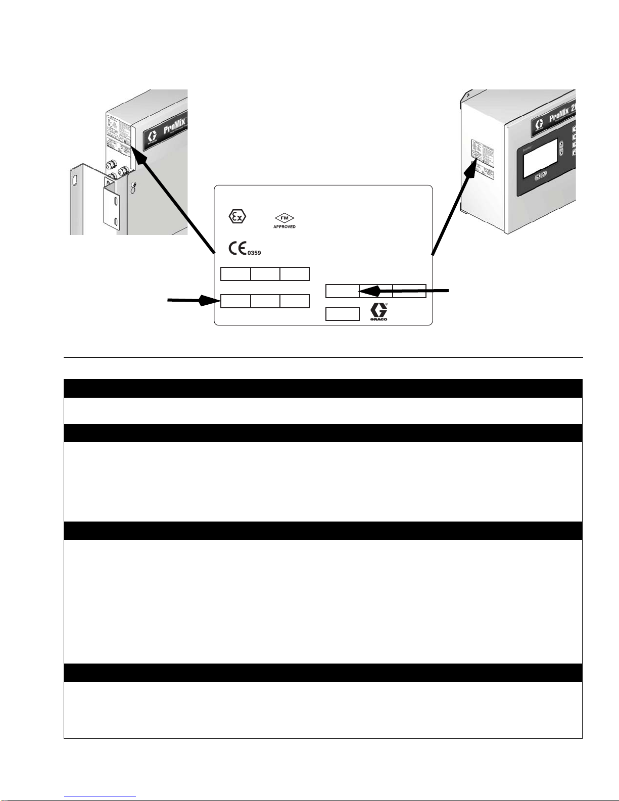
Equipment Approvals . . . . . . . . . . . . . . . . . . . . . . . 3
System Configuration and Part Numbers . . . . . . . 4
Configurator Key . . . . . . . . . . . . . . . . . . . . . . . . . 4
Standard Features . . . . . . . . . . . . . . . . . . . . . . . 6
Accessories . . . . . . . . . . . . . . . . . . . . . . . . . . . . . . . 6
2KS Accessories . . . . . . . . . . . . . . . . . . . . . . . . . 6
2KS Acid Compatible Accessories . . . . . . . . . . . 6
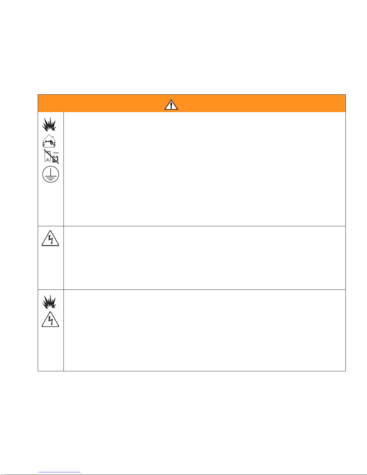
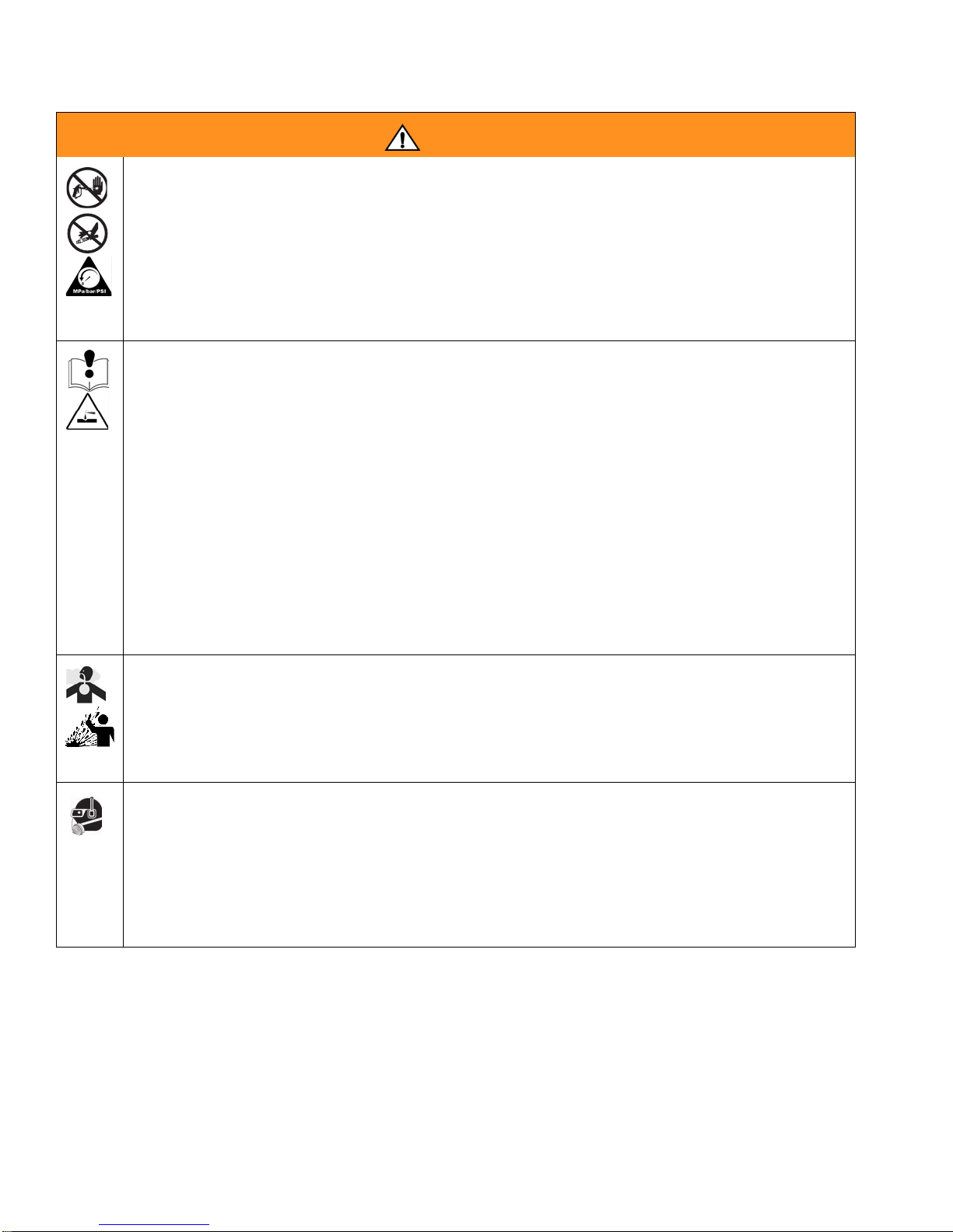
Warnings . . . . . . . . . . . . . . . . . . . . . . . . . . . . . . . . . 7
Important Two-Component Material Information . 9
Isocyanate Conditions . . . . . . . . . . . . . . . . . . . . . 9
Material Self-ignition . . . . . . . . . . . . . . . . . . . . . . 9
Keep Components A and B Separate . . . . . . . . . 9
Moisture Sensitivity of Isocyanates . . . . . . . . . . 10
Changing Materials . . . . . . . . . . . . . . . . . . . . . . 10
Important Acid Catalyst Information . . . . . . . . . . 11
Acid Catalyst Conditions . . . . . . . . . . . . . . . . . . 11
Moisture Sensitivity of Acid Catalysts . . . . . . . . 11
Component Identification and Definition . . . . . . 12
Location . . . . . . . . . . . . . . . . . . . . . . . . . . . . . . . . . 14
Location Requirements . . . . . . . . . . . . . . . . . . . 14
Intrinsically Safe Installation Requirements . . . 14
Optional Cables . . . . . . . . . . . . . . . . . . . . . . . . 14
General Information . . . . . . . . . . . . . . . . . . . . . . . 16
Wall Mounting . . . . . . . . . . . . . . . . . . . . . . . . . . . . 16
Air Supply . . . . . . . . . . . . . . . . . . . . . . . . . . . . . . . . 16
Requirements . . . . . . . . . . . . . . . . . . . . . . . . . . 16
Air Connections . . . . . . . . . . . . . . . . . . . . . . . . . 17
Fluid Supply . . . . . . . . . . . . . . . . . . . . . . . . . . . . . . 18
Requirements . . . . . . . . . . . . . . . . . . . . . . . . . . 18
Fluid Connections . . . . . . . . . . . . . . . . . . . . . . . 18
Setup the Fluid Manifold for Dynamic Dosing . . 20
Solvent Meter Accessory . . . . . . . . . . . . . . . . . . 22
Electrical . . . . . . . . . . . . . . . . . . . . . . . . . . . . . . . . . 23
Requirements . . . . . . . . . . . . . . . . . . . . . . . . . . 23
Connect Main Power . . . . . . . . . . . . . . . . . . . . . 23
Connect EasyKey to Fluid Station Control . . . . 24
Connect Booth Control to Fluid Station Control . 24
Fluid Station Control Board Switch Settings . . . 25
Connect Color Change Module . . . . . . . . . . . . . 26
Grounding . . . . . . . . . . . . . . . . . . . . . . . . . . . . . 29
Check Resistance . . . . . . . . . . . . . . . . . . . . . . . 29
Schematic Diagrams . . . . . . . . . . . . . . . . . . . . . . . 31
System Pneumatic Schematic . . . . . . . . . . . . . . 31
System Electrical Schematic . . . . . . . . . . . . . . . 32
Dimensions and Mounting Hole Layouts . . . . . . 34
Dynamic Dosing Restrictor Selection Graphs . . 36
Technical Data . . . . . . . . . . . . . . . . . . . . . . . . . . . . 43
Graco Standard Warranty . . . . . . . . . . . . . . . . . . . 44
Graco Information . . . . . . . . . . . . . . . . . . . . . . . . . 44

Related Manuals
312775J 3
Related Manuals
Component Manuals in English
Equipment Approvals
Equipment approvals appear on the following labels
which are attached to the Fluid Station and EasyKey™.
See FIG. 1 on page 5 for label locations.
Manual Description
312776 ProMix 2KS Manual System Operation
312777 ProMix 2KS Manual System Repair-Parts
312781 Fluid Mix Manifold
312782 Dispense Valve
312783 Color Change Valve Stacks
312787 Color Change Module Kit
312784 Gun Flush Box Kits
310745 Gun Air Shutoff Kit
312786 Dump Valve and Third Purge Valve Kits
312785 Network Communication Kits
308778 G3000/G3000HR Flow Meter
313599 Coriolis Flow Meter
313290 Floor Stand Kit
313542 Beacon Kit
313386 Basic Web Interface/Advanced Web
Interface
406799 15V256 Automatic System Upgrade Kit
406800 15V825 Discrete I/O Board Kit
Artwork No. 293538
GRACO INC.
P.O. Box 1441
Minneapolis, MN
55440 U.S.A.
.7 7
MAX AIR WPR
MPa bar PSI
FLUID PANEL
ProMix 2KS
100
PART NO. SERIES SERIAL MFG. YR.
CUS
Intrinsically safe equipment
for Class I, Div 1, Group D, T3
Ta = -20°C to 50°C
Install per 289833 FM08ATEX0073
II 2 G
Ex ia IIA T3
®
Artwork No. 293467
SERIES NO. MFG. YR.
PART NO.
AMPS
VOLTS 85-250 ~
2 AMPS MAX
POWER REQUIREMENTS
GRACO INC.
P.O. Box 1441
Minneapolis, MN
55440 U.S.A.
II (2) G
[Ex ia] IIA
FM08ATEX0072
Intrinsically safe connections
for Class I, Div 1, Group D
Ta = -20°C to 50°C
Install per 289833
CUS 50/60 Hz
ProMix 2KS
®
Um: 250 V
ATEX Certificate is listed here
TI13581a
TI13582a
EasyKey Label
Fluid Station Label
EasyKey and Fluid Station Label

System Configuration and Part Numbers
4312775J
System Configuration and Part Numbers
Configurator Key
The configured part number for your equipment is printed on the equipment identification labels. See FIG. 1
for location of the identification labels. The part number includes one digit from each of the following six
categories, depending on the configuration of your system.
Manual
System Control and Display A and B Meter Color Valves Catalyst Valves Applicator Handling
M D = EasyKey with LCD
Display 0 = No Meters
1 = G3000 (A and B)
2 = G3000HR (A and
B)
3 = 1/8 in. Coriolis (A)
and G3000 (B)
4 = G3000(A)and1/8
in. Coriolis (B)
5 = 1/8 in. Coriolis (A)
and G3000HR (B)
6 = G3000HR (A) and
1/8 in. Coriolis (B)
7 = 1/8 in. Coriolis (A
and B)
0 = No Valves
(single color)
1 = Two Valves
(low pressure)
2 = Four Valves (low
pressure)
3 = Seven Valves
(low pressure)
4 = Twelve Valves
(low pressure)
5 = Two Valves
(high pressure)
6 = Four Valves
(high pressure)
0 = No Valves
(single catalyst)
1 = Two Valves
(low pressure)
2 = Four Valves
(low pressure)
3 = Two Valves
(high pressure)
1 = One Air Flow
Switch Kit
2 = Two Air Flow
Switch Kits
3 = One GunFlush Box
Kit
4 = Two GunFlush Box
Kits
M
(acid
models)
D = EasyKey with LCD
Display 8 = G3000 (A) and
G3000A (B) 0 = No Valves
(no color; need
to order acid kit
26A096-26A100;
see page 6)
0 = No Valves
(single catalyst) 1 = One Air Flow
Switch Kit
2 = Two Air Flow
Switch Kits
3 = One GunFlush Box
Kit
4 = Two GunFlush Box
Kits

System Configuration and Part Numbers
312775J 5
FIG. 1: Identification Label
Hazardous Location Approval
Models using a G3000, G3000HR, G3000A, or intrinsically safe Coriolis meter for both A and B meters are
approved for installation in a Hazardous Location - Class I, Div I, Group D, T3 or Zone I Group IIA T3.
Maximum Working Pressure
Maximum working pressure rating is dependent on the fluid component options selected. The pressure rating is
based on the rating of the lowest rated fluid component. Refer to the component pressure ratings below.
Example: Model MD2531 has a maximum working pressure of 3000 psi (21 MPa, 210 bar).
Check the identification label on the EasyKey or fluid station for the system maximum working pressure.
See FIG. 1.
ProMix Fluid Components Maximum Working Pressure
Base System (no meters [option 0], no color/catalyst change [option 0]). . . . . . . 4000 psi (27.58 MPa, 275.8 bar)
Meter Option 1 and 2 (G3000 or G3000HR) . . . . . . . . . . . . . . . . . . . . . . . . . . . . 4000 psi (27.58 MPa, 275.8 bar)
Meter Option 3, 4, 5, 6, and 7 (one or two Coriolis Meters) . . . . . . . . . . . . . . . . . 2300 psi (15.86 MPa, 158.6 bar)
Meter Option 8 (G3000 and G3000A) . . . . . . . . . . . . . . . . . . . . . . . . . . . . . . . . . 4000 psi (27.58 MPa, 275.8 bar)
Color Change Option 1, 2, 3 and 4 and
Catalyst Change Option 1 and 2 (low pressure valves) . . . . . . . . . . . . . . . . . . . . . . . 300 psi (2.07 MPa, 20.6 bar)
Color Change Option 5 and 6 and
Catalyst Change Option 3 (high pressure valves) . . . . . . . . . . . . . . . . . . . . . . . . . . . . 3000 psi (21 MPa, 210 bar)
Flow Meter Fluid Flow Rate Range
G3000 and G3000A . . . . . . . . . . . . . . . . . . . . . . . . . . . . . . . . . . . . . . . . . . . . 75-3800 cc/min. (0.02-1.0 gal./min.)
G3000HR . . . . . . . . . . . . . . . . . . . . . . . . . . . . . . . . . . . . . . . . . . . . . . . . . . . 38-1900 cc/min. (0.01-0.50 gal./min.)
Coriolis Meter . . . . . . . . . . . . . . . . . . . . . . . . . . . . . . . . . . . . . . . . . . . . . . 20-3800 cc/min. (0.005-1.00 gal./min.)
S3000 Solvent Meter (accessory) . . . . . . . . . . . . . . . . . . . . . . . . . . . . . . . . 38-1900 cc/min. (0.01-0.50 gal./min.)
Label Location
on EasyKey
Label Location
on Fluid Station
Maximum Fluid
Working Pressure
is listed here
TI12418a
TI12423a
Configured Part Number

Accessories
6312775J
Standard Features Accessories
2KS Accessories
2KS Acid Compatible
Accessories
Intended for use with acid catalyst materials.
NOTE: This is not a complete list of available accesso-
ries and kits. Refer to the Graco website for more infor-
mation about accessories available for use with this
product.
Feature
EasyKey with LCD
Fiber Optic and Power Cables, 50 ft (15.25 m)
Wall Mount Fluid Station, 50 cc Integrator and Static
Mixer
B Side Dump Valve, if multiple catalyst valves
Booth Control
Basic Web Interface
Accessory
Gun Flush Box Gun Insert Selection
15V354 Third Purge Valve Kit
15V536 Solvent Flow Switch Kit
15V213 Power Cable, 100 ft (30.5 m)
15G710 Fiber Optic Cable, 100 ft (30.5 m)
15U955 Injection Kit for Dynamic Dosing
15V034 10 cc Integrator Kit
15V033 25 cc Integrator Kit
15V021 50 cc Integrator Kit
24B618 100 cc Integrator Kit
15W034 Strobe Light Alarm Indicator Kit
15V337 Advanced Web Interface
15V256 Automatic Mode Upgrade Kit
16D329 S3000 Solvent Flow Meter Kit
15V825 Discrete I/O Integration Board Kit
Accessory
26A096 No Color/1 Catalyst Change Kit
26A097 2 Color/1 Catalyst Change Kit
26A098 4 Color/1 Catalyst Change Kit
26A099 7 Color/1 Catalyst Change Kit
26A100 12 Color/1 Catalyst Change Kit

Warnings
312775J 7
Warnings
The following warnings are for the setup, use, grounding, maintenance, and repair of this equipment. The exclama-
tion point symbol alerts you to a general warning and the hazard symbols refer to procedure-specific risks. When
these symbols appear in the body of this manual, refer back to these Warnings. Product-specific hazard symbols and
warnings not covered in this section may appear throughout the body of this manual where applicable.
WARNING
FIRE AND EXPLOSION HAZARD
Flammable fumes, such as solvent and paint fumes, in work area can ignite or explode. To help prevent
fire and explosion:
• Use equipment only in well ventilated area.
• Eliminate all ignition sources; such as pilot lights, cigarettes, portable electric lamps, and plastic drop
cloths (potential static arc).
• Keep work area free of debris, including solvent, rags and gasoline.
• Do not plug or unplug power cords, or turn power or light switches on or off when flammable fumes
are present.
• Ground all equipment in the work area. See Grounding instructions.
• Use only grounded hoses.
• Hold gun firmly to side of grounded pail when triggering into pail.
• If there is static sparking or you feel a shock, stop operation immediately. Do not use equipment
until you identify and correct the problem.
• Keep a working fire extinguisher in the work area.
ELECTRIC SHOCK HAZARD
This equipment must be grounded. Improper grounding, setup, or usage of the system can cause
electric shock.
• Turn off and disconnect power at main switch before disconnecting any cables and before servicing
equipment.
• Connect only to grounded power source.
• All electrical wiring must be done by a qualified electrician and comply with all local codes and
regulations.
INTRINSIC SAFETY
Intrinsically safe equipment that is installed improperly or connected to non-intrinsically safe equipment
will create a hazardous condition and can cause fire, explosion, or electric shock. Follow local
regulations and the following safety requirements.
• Only models with a G3000, G250, G3000HR, G250HR, G3000A, or intrinsically safe Coriolis meter
are approved for installation in a Hazardous Location - Class I, Div I, Group D, T3 or Zone I Group
IIA T3.
• Do not install equipment approved only for a non-hazardous location in a hazardous area. See the
ID label for the intrinsic safety rating of your model.
• Do not substitute or modify system components as this may impair intrinsic safety.

Warnings
8312775J
SKIN INJECTION HAZARD
High-pressure fluid from gun, hose leaks, or ruptured components will pierce skin. This may look like just
a cut, but it is a serious injury that can result in amputation. Get immediate surgical treatment.
• Tighten all fluid connections before operating the equipment.
• Do not point gun at anyone or at any part of the body.
• Do not put your hand over the spray tip.
• Do not stop or deflect leaks with your hand, body, glove, or rag.
• Follow Pressure Relief Procedure in this manual, when you stop spraying and before cleaning,
checking, or servicing equipment.
EQUIPMENT MISUSE HAZARD
Misuse can cause death or serious injury.
• Do not operate the unit when fatigued or under the influence of drugs or alcohol.
• Do not exceed the maximum working pressure or temperature rating of the lowest rated system
component. See Technical Data in all equipment manuals.
• Use fluids and solvents that are compatible with equipment wetted parts. See Technical Data in all
equipment manuals. Read fluid and solvent manufacturer’s warnings. For complete information
about your material, request MSDS forms from distributor or retailer.
• Check equipment daily. Repair or replace worn or damaged parts immediately with genuine manu-
facturer’s replacement parts only.
• Do not alter or modify equipment.
• Use equipment only for its intended purpose. Call your distributor for information.
• Route hoses and cables away from traffic areas, sharp edges, moving parts, and hot surfaces.
• Do not kink or over bend hoses or use hoses to pull equipment.
• Keep children and animals away from work area.
• Comply with all applicable safety regulations.
TOXIC FLUID OR FUMES HAZARD
Toxic fluids or fumes can cause serious injury or death if splashed in the eyes or on skin, inhaled, or
swallowed.
• Read MSDS’s to know the specific hazards of the fluids you are using.
• Store hazardous fluid in approved containers, and dispose of it according to applicable guidelines.
• Always wear chemically impermeable gloves when spraying or cleaning equipment.
PERSONAL PROTECTIVE EQUIPMENT
You must wear appropriate protective equipment when operating, servicing, or when in the operating
area of the equipment to help protect you from serious injury, including eye injury, inhalation of toxic
fumes, burns, and hearing loss. This equipment includes but is not limited to:
• Protective eyewear
• Clothing and respirator as recommended by the fluid and solvent manufacturer
• Gloves
• Hearing protection
WARNING

Important Two-Component Material Information
312775J 9
Important Two-Component Material Information
Isocyanates (ISO) are catalysts used in two component
materials.
Isocyanate Conditions
Material Self-ignition
Keep Components A and B
Separate
Spraying or dispensing materials that contain
isocyanates creates potentially harmful mists,
vapors, and atomized particulates.
• Read and understand the fluid manufacturer’s
warnings and Safety Data Sheet (SDS) to know
specific hazards and precautions related to
isocyanates.
• Use of isocyanates involves potentially hazardous
procedures. Do not spray with this equipment
unless you are trained, qualified, and have read
and understood the information in this manual and
in the fluid manufacturer’s application instructions
and SDS.
• Use of incorrectly maintained or mis-adjusted
equipment may result in improperly cured
material. Equipment must be carefully maintained
and adjusted according to instructions in the
manual.
• To prevent inhalation of isocyanate mists, vapors,
and atomized particulates, everyone in the work
area must wear appropriate respiratory protection.
Always wear a properly fitting respirator, which
may include a supplied-airrespirator. Ventilate the
work area according to instructions in the fluid
manufacturer’s SDS.
• Avoid all skin contact with isocyanates. Everyone
in the work area must wear chemically
impermeable gloves, protective clothing and foot
coverings as recommended by the fluid
manufacturer and local regulatory authority.
Follow all fluid manufacturer recommendations,
including those regarding handling of
contaminated clothing. After spraying, wash
hands and face before eating or drinking.
Some materials may become self-igniting if applied
too thick. Read material manufacturer’s warnings and
Safety Data Sheet (SDS).
Cross-contamination can result in cured material in
fluid lines which could cause serious injury or
damage equipment. To prevent cross-contamination:
•Never interchange component A and component
B wetted parts.
• Never use solvent on one side if it has been
contaminated from the other side.

Important Two-Component Material Information
10 312775J
Moisture Sensitivity of
Isocyanates
Exposure to moisture (such as humidity) will cause ISO
to partially cure; forming small, hard, abrasive crystals,
which become suspended in the fluid. Eventually a film
will form on the surface and the ISO will begin to gel,
increasing in viscosity.
NOTE: The amount of film formation and rate of crystal-
lization varies depending on the blend of ISO, the
humidity, and the temperature.
Changing Materials
NOTICE
Partially cured ISO will reduce performance and the
life of all wetted parts.
• Always use a sealed container with a desiccant
dryer in the vent, or a nitrogen atmosphere.
Never store ISO in an open container.
• Keep the ISO pump wet cup or reservoir (if
installed) filled with appropriate lubricant. The
lubricant creates a barrier between the ISO and
the atmosphere.
• Use only moisture-proof hoses compatible with
ISO.
• Never use reclaimed solvents, which may
contain moisture. Always keep solvent
containers closed when not in use.
• Always lubricate threaded parts with an
appropriate lubricant when reassembling.
NOTICE
Changing the material types used in your equipment
requires special attention to avoid equipment damage
and downtime.
• When changing materials, flush the equipment
multiple times to ensure it is thoroughly clean.
• Always clean the fluid inlet strainers after
flushing.
• Check with your material manufacturer for
chemical compatibility.
• When changing between epoxies and urethanes
or polyureas, disassemble and clean all fluid
components and change hoses. Epoxies often
have amines on the B (hardener) side. Polyureas
often have aminies on the A (resin) side.

Important Acid Catalyst Information
312775J 11
Important Acid Catalyst Information
The 2KS Plural Component Proportioner is designed for acid catalysts (“acid”) currently used in two-component,
wood-finishing materials. Current acids in use (with pH levels as low as 1) are more corrosive than earlier acids.
More corrosion-resistant wetted materials of construction are required, and must be used without substitution, to
withstand the increased corrosive properties of these acids.
Acid Catalyst Conditions
Moisture Sensitivity of Acid
Catalysts
Acid catalysts can be sensitive to atmospheric moisture
and other contaminants. It is recommended the catalyst
pump and valve seal areas exposed to atmosphere are
flooded with ISO oil, TSL, or other compatible material
to prevent acid build-up and premature seal damage
and failure.
Acid is flammable, and spraying or dispensing acid creates potentially harmful mists, vapors, and atomized
particulates. To help prevent fire and explosion and serious injury:
• Read and understand the fluid manufacturer’s warnings and Safety Data Sheet (SDS) to know specific
hazards and precautions related to the acid.
• Use only genuine, manufacturer’s recommended acid-compatible parts in the catalyst system (hoses,
fittings, etc). A reaction may occur between any substituted parts and the acid.
• To prevent inhalation of acid mists, vapors, and atomized particulates, everyone in the work area must
wear appropriate respiratory protection. Always wear a properly fitting respirator, which may include a
supplied-air respirator. Ventilate the work area according to instructions in the acid manufacturer’s SDS.
• Avoid all skin contact with acid. Everyone in the work area must wear chemically impermeable gloves,
protective clothing, foot coverings, aprons, and face shields as recommended by the acid manufacturer
and local regulatory authority. Follow all fluid manufacturer recommendations, including those regarding
handling of contaminated clothing. Wash hands and face before eating or drinking.
• Regularly inspect equipment for potential leaks and remove spills promptly and completely to avoid direct
contact or inhalation of the acid and its vapors.
• Keep acid away from heat, sparks, and open flames. Do not smoke in the work area. Eliminate all ignition
sources.
• Store acid in the original container in a cool, dry, and well-ventilated area away from direct sunlight and
away from other chemicals in accordance with acid manufacturer’s recommendations. To avoid corrosion
of containers, do not store acid in substitute containers. Reseal the original container to prevent vapors
from contaminating the storage space and surrounding facility.
NOTICE
Acid build-up will damage the valve seals and reduce
the performance and life of the catalyst pump. To pre-
vent exposing acid to moisture:
• Always use a sealed container with a desiccant
dryer in the vent, or a nitrogen atmosphere.
Never store acids in an open container.
• Keep the catalyst pump and the valve seals filled
with the appropriate lubricant. The lubricant
creates a barrier between the acid and the
atmosphere.
• Use only moisture-proof hoses compatible with
acids.
• Always lubricate threaded parts with an
appropriate lubricant when reassembling.

Component Identification and Definition
12 312775J
Component Identification and Definition
FIG. 2. Manual System, shown with G3000 Meters, Color/Catalyst Change, One Gun Flush Box, and
Accessory Solvent Flow Meter
TI29655a
EK
BC*
ST
ACV
CCM*
MS
MA
MB
FM
GFB
BCV
FO*
PS*
Air Controls/
Filter
* See the ProMix 2KS
Repair-Parts manual for
optional cable lengths.
BCV - acid models
Table 1: Component Descriptions
Component Description
EasyKey (EK) Used to set up, display, operate, and monitor the system. The EasyKey accepts 85-250 VAC,
50/60 Hz line power and converts that power to acceptable low voltage and optical signals
used by other system components.
Booth Control (BC) Used by the operator for daily painting functions including: choosing recipes, initiating job com-
plete, reading/clearing alarms, and placing the system in Standby, Mix, or Purge mode. It is
typically mounted inside the booth or near the painter.
Fluid Station (ST) Includes air control solenoids, flow switches, and mountings for the fluid flow meters and the
fluid manifold assembly. Its control board manages all proportioning functions.

Component Identification and Definition
312775J 13
Fluid Manifold (FM) •Pneumatically Operated Dose Valves for component A and B
•Purge Valves for solvent and air purge
•Sampling Valves for calibrating the flow meters and performing ratio checks
•Shutoff Valves for component A and B to close their fluid passages to the mix manifold, to
allow for accurate calibration and ratio checks
•Mix Manifold, which includes the fluid integrator and static mixer.
Fluid Integrator is the chamber where component A and B align at the selected
ratio and begin to mix.
Static Mixer has 24 elements to uniformly blend the materials downstream of the
fluid integrator.
Flow Meters (MA,
MB, MS) The following optional flow meters are available from Graco:
•G3000 is a general purpose gear meter typically used in flow ranges of 75-3800 cc/min.
(0.02–1.0 gal/min.), pressures up to 4000 psi (28 MPa, 276 bar), and viscosities of
20–3000 centipoise. The K-factor is approximately 0.119 cc/pulse.
•G3000A is a gear meter for use with acid catalyst fluids. It is typically used in flow ranges
of 75-3800 cc/min. (0.02–1.0 gal/min.), pressures up to 4000 psi (28 MPa, 276 bar), and
viscosities of 20–3000 centipoise. The K-factor is approximately 0.119 cc/pulse.
•G3000HR is a high resolution version of the G3000 meter. It is typically used in flow
ranges of 38–1900 cc/min. (0.01–0.5 gal/min.), pressures up to 4000 psi (28 MPa, 276
bar). and viscosities of 20–3000 centipoise. The K-factor is approximately 0.061 cc/pulse.
•S3000 is a gear meter used for solvents in flow ranges of 38-1900 cc/min. (0.01–0.50
gal/min.), pressures up to 3000 psi (21 MPa, 210 bar), and viscosities of 20–50 centipoise.
The K-factor is approximately 0.021 cc/pulse. Required to use the Solvent Push feature.
•Coriolis is a specialty meter capable of a wide range of flow rates and viscosities. This
meter is available with 1/8 in. or 3/8 in. diameter fluid passages. For detailed information
on the Coriolis meter, see manual 313599.
The K-factor is user-settable; at lower flow rates use a lower K-factor.
1/8 in. fluid passages: set K-factor to .020 or .061.
3/8 in. fluid passages: set K-factor to .061 or 0.119.
Color Change Valves
(ACV) and Color
Change Module
(CCM)
An optional component. It is available as a color change valve stack for either low or high pres-
sure with up to 30 color change valves. Each stack includes one additional valve for solvent to
clean the fluid line between color changes.
Catalyst Change
Valves (BCV) An optional component. It is available as a catalyst change valve stack for either low or high
pressure with up to 4 catalyst change valves. Each stack includes one additional valve for sol-
vent to clean the fluid line between catalyst changes.
A different catalyst change valve is used on acid catalyst systems.
Dual Fiber Optic
Cable (FO) Used to communicate between the EasyKey and Wall Mount Fluid Station.
Fluid Station Power
Supply Cable (PS) Used to provide power to the Wall Mount Fluid Station.
Applicator Handling:
use Air Flow Switch
(AFS) or Gun Flush
Box (GFB)
Air Flow Switch: The air flow switch detects air flow to the gun and signals the ProMix control-
ler when the gun is being triggered. The switch functions with the flow meters to ensure that
the system components are functioning correctly. See the system operation manual for further
information.
Gun Flush Box: The gun flush box kit provides an automated flushing system for manual
spray guns, and includes an air flow switch.
Table 1: Component Descriptions
Component Description

Location
14 312775J
Location
Location Requirements
• Mount EasyKey and Fluid Station within 50 ft (15.2
m) of each other, using 15U533 cable.
NOTE: An optional 15V213 100 ft (30.5 m) cable is
also available.
•EasyKey: Install in the non-hazardous area at a
convenient location for the operator to view and
operate.
•Fluid Station: Install according to requirements for
Intrinsically Safe Installation (FIG. 3) and at a conve-
nient location to connect to paint and solvent sup-
plies.
NOTE: For an Intrinsically Safe Installation, the
Fluid Station may be located inside or outside the
hazardous location. Install according to appropriate
electrical codes.
•Booth Control: Install in the hazardous area at a
convenient location for the operator to view and
operate. Mount using the wall bracket (see page
35).
Intrinsically Safe Installation
Requirements
See FIG. 3 on page 15.
1. The non-intrinsically safe terminals (power rail) must
not be connected to any device which uses or gen-
erates more than 250 Vrms or dc unless it has been
determined that the voltage has been adequately
isolated.
2. The installation must meet the requirements of the
National Electric Code, Canadian Electrical Code
Part I, NFPA 70, Article 504 Resp., Article 505 and
ANSI/ISA 12.06.01.
3. Multiple earthing of components is allowed only if
high integrity equipotential system is realized
between the points of bonding.
4. Do not operate system with safety barrier cover
removed.
5. For ATEX, install per EN 60079-14 and applicable
local and national codes.
6. For power connection to Coriolis: Install Coriolis
flow meters as explosion proof (USA, Can-
ada)/flameproofEx d (ATEX) per the manufacturer’s
installation instructions and applicable codes.
7. For signal to 2KS: Terminals 24 and 25 of optional
Endress+HauserCoriolis flow meters installed using
intrinsically safe wiring methods.
8. For ATEX installations, interconnecting cabling
specified is Type A cable in accordance with EN
60079-14.
Optional Cables
Optional CAN cables and fiber optic cables are available
from Graco. See the ProMix 2KS Repair-Parts manual
for available part numbers and lengths.
Do not substitute or modify system components as this
may impair intrinsic safety. For installation, mainte-
nance or operation instructions, read instruction manu-
als. Do not install equipment approved only for
non-hazardous location in a hazardous area. See the
identification label (FIG. 1) on the EasyKey or fluid sta-
tion for the intrinsic safety rating for your model.

Location
312775J 15
FIG. 3. Intrinsically Safe Installation
NON-HAZARDOUS
LOCATION ONLY HAZARDOUS (CLASSIFIED) LOCATION
CLASS I, DIV I, GROUP D, T3 (US AND CANADA)
CLASS I, ZONE I GROUP IIA T3 (ATEX ONLY)
TAUB = -20°C TO 50°C
ProMix 2KS
EasyKey Interface Safety
Barrier
ProMix 2KS Smart Fluid Plate
(Wall Panel or RoboMix
Flow
Meter
A
Flow
Meter
B
Booth Control
Module
FM08ATEX0073
Color & Catalyst
Change
Module 1
FM08ATEX0073
250 VAC Maximum
Supply Voltage
50’ I/S Power Cable
(3’, 6’, 10’, 15’, 25’,
100’ options)
50’ Fiber Optic
Communication
Cable (100’ option)
10’ I/S Power and
Communication
Cable (40’
extension option)
IS Control Drawing 289833
Cable
Module 2
FM08ATEX0073
Flow Control
Regulator
Module
FM08ATEX0073
3’ CAN Color
Change Interface
(6’, 10’, 15’, 25’,
50’ 100’ options)
50’ CAN Booth
Control Interface
(3’, 6’, 10’, 15’,
25’, 100’ options)
3’ CAN
Network
Cable
NOTE: See Intrinsically Safe Installation
Requirements on page 14.
WARNING: Substitution of components
may impair intrinsic safety. For installation,
maintenance or operation instructions, see
instruction manual.
ADVERTISSEMENT: La substitution de
composants peut compromettre la securite
intrinseque.
FM08ATEX0074
SYSTEM ASSEMBLY CERTIFICATE
FM08ATEX0072
ASSOCIATED APPARATUS
FM08ATEX0073 INTRINSIC
SAFE APPARATUS
Coriolis Meter Options, DMT 00 ATEX E 074 X (No exceptions):
Size Graco P/N Endress+Hauser P/N
1/8” 15T633* 80A-04-A-SVW-9-A-N-A-B-B-A-S
3/8” 15T634* 801-08-A-999-9-A-N-A-B-B-A-S
1/8” 16M510* 8CN04-84S89AABA9AC
1/4” 16M519* 8CN06-84S89AABA9AC
Power
EasyKey
+24 Vdc
Common
Meter Terminal Block #
1
2
Signal
Fluid Plate Board J3 Terminal Meter Terminal Block #
Meter Position A B
Signal 3 6 24
Common 2 5 25
* For P/N 15T633 order Coriolis Meter Kit 15V806.
For P/N 15T634 order Coriolis Meter Kit 258151.
For P/N 16M510 order Coriolis Meter Kit 24M260.
For P/N 16M519 order Coriolis Meter Kit 24M261.

General Information
16 312775J
General Information
• Reference numbers and letters in parentheses in
the text refer to numbers and letters in the illustra-
tions.
•F
IG. 2, page 12, shows the basic components of a
manual system. Contact your Graco distributor for
actual system designs.
• Be sure all accessories are adequately sized and
pressure-rated to meet system requirements.
• There must be a shutoff valve between each fluid
supply line and the ProMix system.
• A 100 mesh minimum fluid filtermust be installed on
component A and B fluid supply lines.
• To protect the EasyKey screens from paints and
solvents, clear-plastic protective shields are avail-
able in packs of 10 (Part No. 197902). Clean the
screens with a dry cloth if necessary.
Wall Mounting
1. See Dimensions and Mounting Hole Layouts,
page 34.
2. Ensure that the wall and mounting hardware are
strong enough to support the weight of the equip-
ment, fluid, hoses, and stress caused during opera-
tion.
3. Using the equipment as a template, mark the
mounting holes on the wall at a convenient height
for the operator and so equipment is easily accessi-
ble for maintenance.
4. Drill mounting holes in the wall. Install anchors as
needed.
5. Bolt equipment securely.
Air Supply
Requirements
•Compressed air supply pressure: 75-100 psi
(517-700 kPa, 5.2-7 bar).
•Air hoses: use grounded hoses that are correctly
sized for your system.
•Air regulator and bleed-type shutoff valve:
include in each air line to fluid supply equipment.
Install an additional shutoff valve upstream of all air
line accessories to isolate them for servicing.
•Air line filter: a 10 micron or better air filter is rec-
ommended to filter oil and water out of the air supply
and help avoid paint contamination and clogged
solenoids. See FIG. 2.
Trapped air can cause a pump or dispense valve to
cycle unexpectedly, which could result in serious injury
from splashing or moving parts. Use bleed-type shutoff
valves.

Air Supply
312775J 17
Air Connections
See the System Pneumatic Schematic on page 31.
1. Tighten all ProMix system air and fluid line connec-
tions as they may have loosened during shipment.
2. Install a bleed-type air shutoff valve into the control
air filter inlet on Wall Mount Fluid Station. FIG. 4.
3. Connect a clean, dry, main air supply line to the
bleed-type air shutoff valve at the main air inlet. This
air line supplies air to operate the gun, solenoids,
and dispense valves.
NOTE: See Technical Data on page 43 for additional
air supply/consumption information.
4. lnstall a bleed-type shutoff valve into the air purge
valve line.
5. See FIG. 5. Install the supplied elbow (E), check
valve (CV), and tube fitting (F) at the inlet of the air
purge valve (APV). Use the 25 ft (7.6 m), 1/4 in. (6
mm) OD purge air tubing (AT, supplied) to connect
a clean, dry air supply to the fitting (F) at the air
purge valve inlet. Install filters/dryers as needed.
FIG. 4. Wall Mount Air Supply Inlet
NOTICE
Use a separate purge air supply line for the air purge
valve (APV). Do not connect the air purge valve to the
unit’s main air supply or to the air manifold (AM, FIG.
4), to avoid contaminating the solenoids, air logic
lines, or unit’s main air supply with fluid if the air purge
valve (APV) and check valve (CV) fail.
Do not shorten the 25 ft (7.6 m), 1/4 in. (6 mm) OD
purge air tubing (AT). Check daily for any visible sol-
vent accumulation. Notify your supervisor if solvent is
present.
TI13069a
1
Install a bleed-type air shutoff valve here.
1
Main Air
Inlet
Air Filter
AM
FIG. 5. Purge Air Supply Tube and Check Valve
NOTICE
The ProMix potlife timer will not function properly
when used with multiple guns operating simultane-
ously. To avoid having mixed material set in the
equipment, carefully monitor potlife by some other
means.
If using a Graco electrostatic PRO™Gun, a shutoff
valve must be installed in the gun air line to shutoff the
atomizing and turbine air to the gun. Contact your
Graco distributor for information on air shutoff valves
for electrostatic applications.
AT
TI16793a
CV
APV
F
E
Purge air line (AT) must be a separate air supply, connected
to the check valve (CV). Do not connect the purge air line to
the unit’s main air supply or to the air manifold.
2
2

Fluid Supply
18 312775J
Fluid Supply
Requirements
ProMix models are available to operate air spray or
air-assisted systems with a capacity of up to 3800
cc/min.
• Fluid supply pressure tanks, feed pumps, or circu-
lating systems can be used.
• Materials can be transferred from their original con-
tainers or from a central paint recirculating line.
• For an airless system, the user must supply a gun
trigger signal to the ProMix 2KS.
• See manual 313599 for Coriolis meter installation
and operation instructions.
• If you are using dynamic dosing, see Fluid Connec-
tions at right and also see Setup the Fluid Mani-
fold for Dynamic Dosing on page 20.
NOTE: The fluid supply must be free of pressure spikes,
which are commonly caused by pump stroke change-
over. If necessary, install pressure regulators or a surge
tank on the ProMix fluid inlets to reduce pulsation. Con-
tact your Graco distributor for additional information.
Fluid Connections
1. Connect the solvent supply lines.
a. Connect the solvent supply line to the 1/4 npt(f)
solvent purge valve inlet. See FIG. 6.
b. Multiple color system: also connect a solvent
supply line to the color change stack (Q), top
valve 4 or 5. See FIG. 7.
NOTE: Solvent supplied by a single source can cause
cross contamination and damage to the system. Install
check valves or use separated solvent sources.
2. Connect the component A supply line(s).
Single color system: connect component
supply line to the component A flow meter
inlet.
Multiple color system: connect compo-
nent A supply lines to the color change
valve stack (S) inlets. See FIG. 7. The color
number is marked on the valve air supply
line.
NOTE: Paint Recirculating System Only
• The color change valves have two fluid
ports for each individual valve. If you are
recirculating paint, plumb the valves in one
port and out the other.
• Another option is to use a tee fitting to recir-
culate.
NOTE: Verify that all unused fluid ports on the color
change valve stack are plugged before operation. An
open port will leak fluid.
3. Connect the component B line to the component B
flow meter inlet.
NOTE: The component A and B fluid meter inlets have
fluid check valves to prevent backflow from fluid supply
pressure fluctuations. Backflow can cause ratio inaccu-
racies.
4. Connect the gun fluid supply line between the fluid
manifold static mixer outlet and the gun fluid inlet.
Do not exceed the pressure rating of the lowest rated
component. See the identification label (FIG. 1 on page
5).
To reduce the risk of injury, including fluid injection,
you must install a shutoff valve between each fluid sup-
ply line and the fluid manifold assembly. Use the
valves to shut off fluid during maintenance and service.

Fluid Supply
312775J 19
FIG. 6. Wall Mount Fluid Station, Sequential Dosing
TI12556b
Key:
MA Component A Meter
DVA Component A Dose Valve
RVA Component A Sampling Valve
SVA Component A Shutoff Valve
MB Component B Meter
DVB Component B Dose Valve
RVB Component B Sampling Valve
SVB Component B Shutoff Valve
MS Solvent Meter (accessory)
SPV Solvent Purge Valve
APV Air Purge Valve
SM Static Mixer
FI Fluid Integrator
AT Air Purge Valve Air Supply Tube
MA
MB
DVB
MS
SPV
DVA
APV SM
FI
SVA SVB
RVB
RVA
AT
FIG. 7. Color Change Valves Air and Fluid Connections
Q
S
1
2
4
5
3
Connect solvent valve
air line here
Color Change Board and Solenoid Valves
Color Change BoardSolenoids
Color Change Valve Stack
Connect air lines to
valves here
Fluid Inlets Fluid Inlets
Fluid Outlet
TI12824a TI11668a

Fluid Supply
20 312775J
Setup the Fluid Manifold for Dynamic Dosing
If you will be operating using dynamic dosing, the fluid
manifold must be setup properly for your application.
Order the 15U955 Injection Kit (accessory).
1. Remove the screws (A) and static mixer bracket
assembly (B). See FIG. 8.
2. Loosen the static mixer nut (N1). Remove and retain
the static mixer (SM).
3. Loosen the u-tube nuts (N2 and N3). Discard the
u-tube (C) and the static mixer fitting (D).
4. Remove and retain the 1/4 npt(m) fitting (F).
Remove the integrator (G) and discard.
5. See FIG. 9. Remove the remaining parts from the
restrictor housing (H). Retain the plug (J) and base
(K). Discard all the used o-rings,
6. Rotate the restrictor housing (H) 180° so the set-
screw (S) is at top left, as shown in FIG. 9. Remove
and retain the two setscrews (S). Discard the
o-rings (L3). The position of these screws will be
reversed when reassembled.
7. Install one larger o-ring (L1*) in the housing (H).
Screw the injection cap (M*) into the housing.
8. Determine the desired flow range for your applica-
tion. Select the appropriate size restrictor for your
selected flow and ratio, using the Dynamic Dosing
Restrictor Selection Graphs on pages 36-41 as a
guide. Install the restrictor (R*) in the base (K).
9. Assemble the smaller manifold o-ring (L2*), restric-
tor (R*) and base (K), one larger o-ring (L1*), and
plug (J) as shown.
FIG. 8. Disassemble Integrator and Static Mixer
N1
A
B
SM
C
D
TI15004a
F
G
N2 N3
FIG. 9. Install 15U955 Injection Kit
L1*
L2*
H
K
M*
SM
J
N1
TI13360b
L1*
F
S
R*
* These parts are included in the
15U955 Injection Kit.
L3*
Other manuals for ProMix 2KS
3
Table of contents
Other Graco Mixer manuals

Graco
Graco Hydra-Cat 207-388 F Datasheet

Graco
Graco PrecisionMix ii Datasheet

Graco
Graco ProMix II User manual

Graco
Graco XTREME MIX 309521J User manual

Graco
Graco ProMix II Series Guide

Graco
Graco DataTrak kit User manual

Graco
Graco ToughTek CM20 Instruction Manual

Graco
Graco Twistork A Series Operation manual

Graco
Graco 25C483 Parts list manual

Graco
Graco ProMix Easy Series User manual