General Safety
This equipment generates very high fluid pressure. Spray from
the gun, leaks or ruptured components can inject fluid
through your skin and into your body and cause extremely
serious bodily injury, including the need for amputation. Also,
fluid injected or splashed into the eyes can cause serious
damage.
NEVER point the spray gun or dispensing valve at anyone or at
any part of the body. NEVER put hand or fingers over the
spray tip or nozzle. NEVER try to “blow back” fluid; this is
NOT an air spray system.
ALWAYS follow the Pressure Relief Procedure, below,
before
cleaning or removing the spray tip or nozzle or servicing
any system equipment.
NEVER try to stop or deflect leaks with your hand or body.
Be sure equipment safety devices are operating properly
before each use.
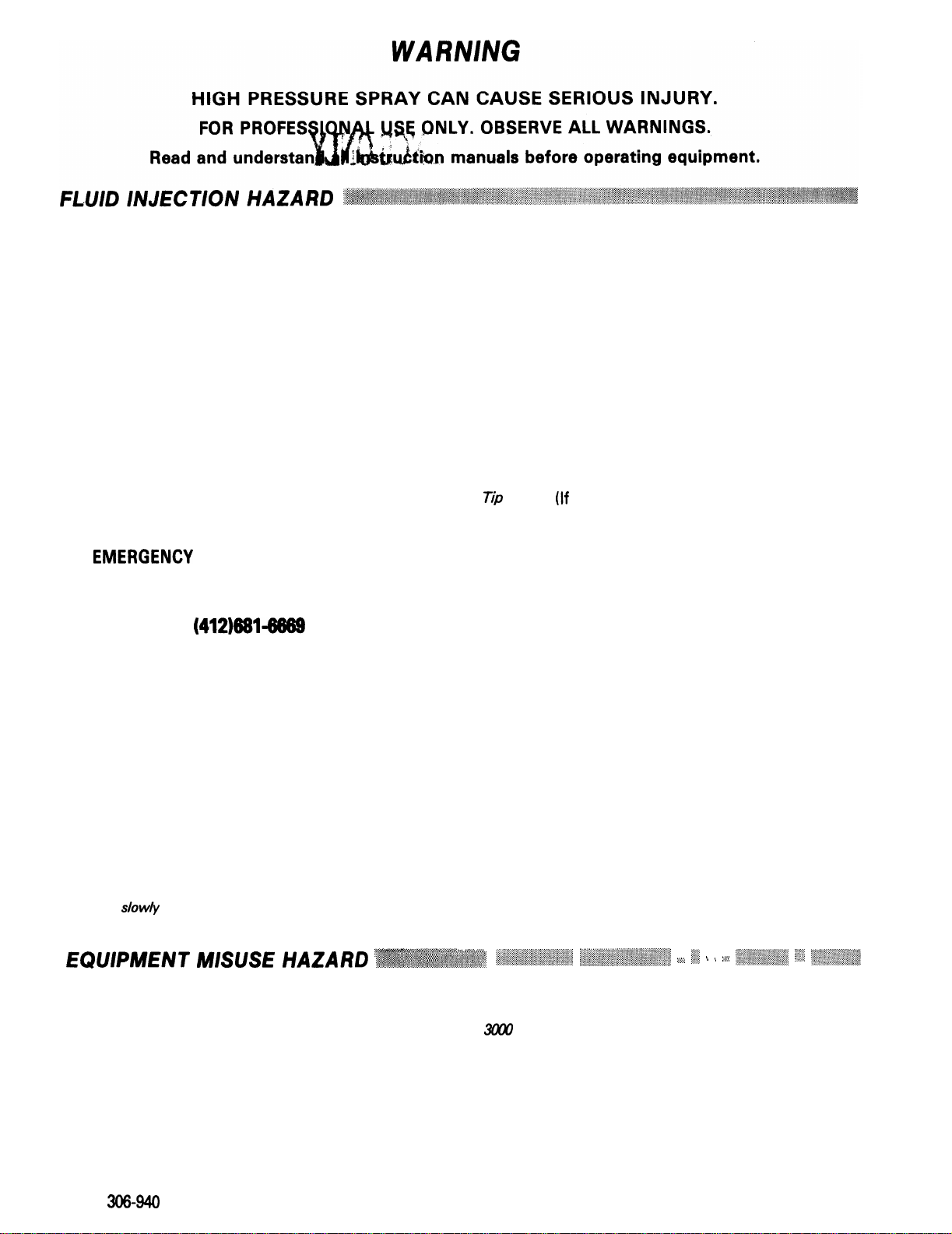
Medical Treatment
If any fluid appears to penetrate your skin, get
EMERGENCY
MEDICAL CARE AT ONCE.
DO NOT TREAT AS A SIMPLE CUT.
Tell the doctor exactly what fluid was injected. For treatment
instructions, have your doctor call the
NATIONAL POISON CENTER NETWORK
(412)681-6869
Pressure Relief Procedure
To reduce the risk of serious bodily injury, including injection,
always follow this procedure whenever the pump is shut off,
when checking or servicing any part of the system, when in-
stalling or changing spray tips, and whenever you stop spray-
ing.
1.
Close the mixer material valves.
2.
Open the solvent flush valve(s) and flush until clean.
3.
Shut off the material and solvent pumps.
4. Open the spray gun or dispensing valve to relieve
pressure.
5.
If material has hardened in the hose or mixer, close the
material valve, shut off the material and solvent pumps,
and slow/yloosen the material inlet hose(s) to relieve
pressure, then remove the dispensing hose.
Spray Gun or Dispensing Valve Safety Devices
Be sure all gun safety devices are operating properly before
each use. Do not remove or modify any part of the gun; this
can cause a malfunction and result in serious bodily injury.
Safety Latch (If your gun is equipped with one)
Whenever you stop spraying, even for a moment, always set
the gun safety latch in the closed or “safe” position, making
the gun inoperative. Failure to set the safety latch can result in
accidental triggering of the gun.
Diffuser (If your gun is equipped with one)
The diffuser breaks up spray and reduces the risk of injection
when the tip is not installed. Check diffuser operation regular-
ly. Follow the Pressure Relief Procedure, below, then
remove the spray tip. Aim the gun into a metal pail, holding
the gun firmly to the pail. Using the lowest possible pressure,
trigger the gun. If the fluid emitted is
not
diffused into an ir-
regular stream, replace the diffuser immediately.
fip Guard (If your gun is equipped with one)
ALWAYS have the tip guard in place on the spray gun while
spraying. The tip guard alerts you to the injection hazard and
helps prevent accidentally placing your fingers or any part of
your body close to the spray tip.
Trigger Guard (If your gun is equipped with one)
NEVER
operate the gun with the trigger guard removed. The
guard helps prevent the gun from triggering accidentally if it is
dropped.
Spray Tip or Nozzle Safety
Use
extreme caution when cleaning or changing spray tips or
nozzle. If the spray tip or nozzle clogs while spraying, engage
the gun safety latch immediately. ALWAYS follow the
Pressure Relief Procedure and then remove the spray tip to
clean it.
NEVER
wipe off build up around the spray tip or nozzle until
pressure is fully relieved and the gun safety latch is engaged.
“~%**?.Y”
<+
‘9.y
+*i
EQUIPMENT
M/S(JSE
HAZARD
~~~~~~~~~~~~~~~,~;.:-
y+J~~
“‘X
:q+&.&&,>: ,:,,~.~~i;:‘::,~~,,~,.,~;,:~:
:;,:~.I:~.‘.~;:~~:,~~,‘,~:.‘,
:.,
:‘.I:.
<
.,
.:
‘:$;<I.ty:,;I;;,
:‘,..
‘.;.‘-,“‘.-;:;;~
General Safety System Pressure
Any misuse of the spray equipment or accessories, such as Never exceed the maximum working pressure of the lowest
overpressurizing, modifying parts, using incompatible rated equipment in your spray system. This manifold has a
chemicals and materials, or using worn or damaged parts, can
3cKx)
psi (210 bar) MAXIMUM WORKING PRESSURE. Be
cause them to rupture and result in injection or other serious sure that all fluid and air accessories you add to the spray
bodily injury, fire, explosion or property damage. system are properly rated to withstand the maximum air and
fluid working pressures of this system.
NEVER alter or modify any part of this equipment; doing so
could cause it to malfunction.
CHECK all spray equipment regularly and repair or replace
worn or damaged parts immediately.
Material Compatibility
BE SURE that all materials and solvents used are chemically
compatible with the wetted parts shown in the Technical Data
on the back cover. Always read the material and solvent
manufacturer’s literature before using them in this sprayer.
2
306-940