Setup
Using Fluid Set Charts
Turbine
Spray Gun includes a #3 fluid set, part no.
240–113.
The size of air cap, fluid nozzle, and fluid
needle are marked on parts.
Use fluid set charts on page 10 to order different size
fluid set or to find part number of individual compo
-
nents of fluid set. Charts identify fluid sets used in
contractor and automotive applications.
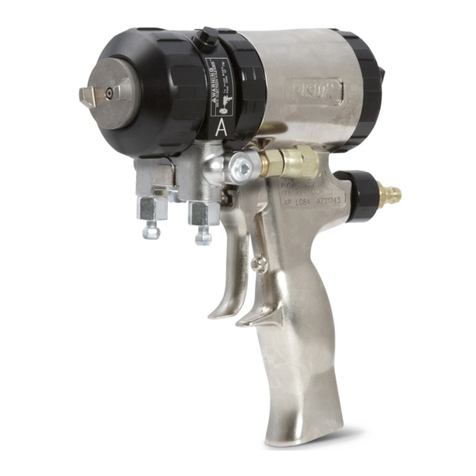
Fluid sets include air cap (A), nozzle (B), and
needle assembly (D). See Fig. 1
1.
NOTE:
T
o order other replacement parts for gun, see
parts drawing and list for gun model on page 20.
Fig. 11 02981
A
B
C
Fluid Set
D
Selecting Fluid Set
Turbine
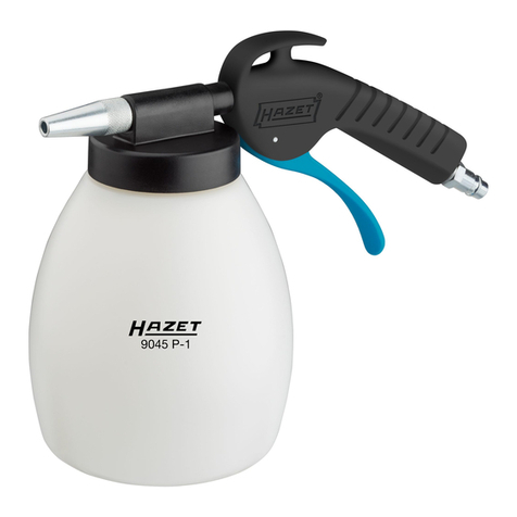
spray gun fluid sets range in size to provide
dif
ferent fluid flow rates. Selection charts on page 10
show recommended combinations based on fluid
viscosities, flow rates, and usage.
As a general guideline,
use fluid nozzle that will give
required flow with needle fully triggered at lowest fluid
pressure.
For low flow rates or light viscosity fluid,
select smaller
nozzle sizes.
For high flow rates or high viscosity fluid,
select larger
nozzle sizes.
T
o eliminate mist,
use air cap one size larger than fluid
nozzle. Use of smaller size air cap produces finer
finish, but can increase mist.
For very fine finish work (automotive, furniture, etc.),
order air cap two sizes smaller than needle and nozzle.
0.5M mm or 0.7M mm multi-hole air caps are recom
-
mended for automotive finishes. See
Automotive
User Chart
on page 10.
For narrow fan pattern (wood finishing)
, order 0.5W
mm, 0.7W mm, or 1.0W mm narrow fan pattern air
cap. See chart below for part numbers.
Narrow Fan Pattern Air Caps
Air Cap P/N Size
M70–435
0.5W mm
M70–438
0.7W mm
M70–441
1.0W mm
Shutdown
Pressure Relief Procedure
WARNING
PRESSURIZED
EQUIPMENT HAZARD
The equipment stays pressurized until pressure is
manually relieved. To reduce the risk of a serious
injury from pressurized fluid, accidental spray from
the gun, or splashing fluid, follow the
Pressure Re
-
lief Procedure
whenever you:
are instructed to relieve the pressure,
stop spraying,
check or service any of the system equipment,
or install or clean the fluid nozzles.
1.
When spraying is finished, turn of
f air supply to
gun.
2. T
urn of
f turbine sprayer
.
WARNING
The turbine hose outlet may be hot. Carefully
check the hose end before removing the hose.
3.
If using remote pressure pot,
relieve pressure by
following these steps:
a. T
urn of
f air supply to pressure pot.
b.
2 1/2 Gallon Remote Pot:
Pull pressure relief
valve ring (206c) until pressure is completely
relieved.
2 Quart Remote Pot:
Turn out
pressure relief
knob (1
13) about one turn. W
ait until pressure
is completely relieved before removing cover
.
Close knob. See Fig. 12.