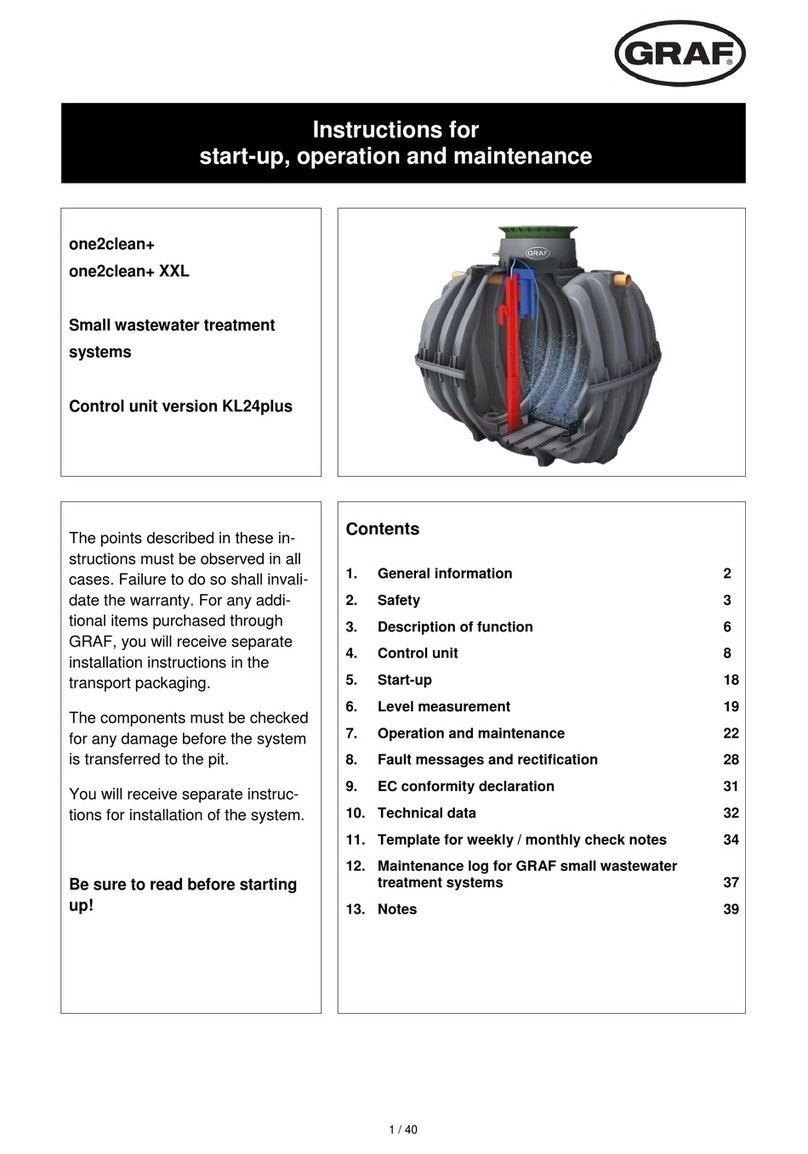
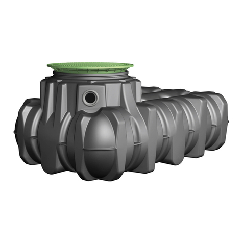
Graf UP Series User manual

GRAF UP
DE
Montageanleitung für GRAF UP
>> Seite 1-8
EN
Assembly instructions for GRAF UP
>> Page 9-16
FR
Notice de montage pour GRAF UP
>> Page 17-24
Instrucciones de montaje de la Duperadora GRAF UP
>> Página 25-32
ES

www.graf.info
Montageanleitung für GRAF UP
160470 UPone 3 EW, 2000 L
160471 UPone 6 EW, 4000 L
160475 UPtwo 5 EW, 2 x 2000 L
160476 UPtwo 10 EW, 2 x 4000 L
Die in dieser Anleitung beschrie-
benen Punkte sind unbedingt zu
beachten. Bei Nichtbeachtung er-
lischt jeglicher Garantieanspruch.
Für alle über GRAF bezogenen
Zusatzartikel erhalten Sie separate
in der Transportverpackung beilie-
gende Einbauanleitungen.
Eine Überprüfung der Bauteile auf
eventuelle Beschädigungen hat
unmittelbar nach Anlieferung zu
erfolgen.
Für Betrieb und Wartung der Anla-
ge stehen ihnen auf unserer
Homepage zum Download bereit,
die Links dazu finden Sie im Kapi-
tel 5 dieser Anleitung.
Inhaltsübersicht
1. LIEFERUMFANG 2
2. INSTALLATION DER KLÄRTECHNIK 3
2.1Montage des Vorklärbehälters (nur bei UPtwo) 3
2.2Montage des Tellerbelüfters in den SBR-Behälter
(UPone und UPtwo) 3
2.3Anschluss der Schlammrückführung (nur UPtwo) 4
2.4Anschluss der Probeentnahme und Auflauf 4
2.5Anschluss der Entlüftung 5
3. MONTAGE SCHALTSCHRANK 6
3.1Auswahl des Standortes 6
3.2Montage EPP-Innenschrank 6
4. ANSCHLIEßEN DER LUFTSCHLÄUCHE 7
4.1Anschluss der Luftschläuche bei der UPone 7
4.2Anschluss der Luftschläuche bei der UPtwo 7
5. INBETRIEBNAHME 8

1. Lieferumfang
2 / 32
1. Lieferumfang
Die Kläranlage GRAF Up ist in zwei Varianten erhältlich:
GRAF UPone Einbehälteranlage ohne Vorklärung mit Schlammstabilisation
GRAF UPtwo Zweibehälteranlage mit Vorklärbehälter und Schlammspeicher
UPone UPtwo
Lieferumfang:
Ein Behälter mit vormontierter
Klärtechnik bestehend aus:
Zulaufschikane
Klarwasserheber
Vorklärbehälter
SBR-Behälter mit
Zulaufschikane
Klarwasserheber
Tellerbelüfter Tellerbelüfter
Rohre und Bögen für Probe-
entntnahme
T-Stück als Ablaufschikane in
der Vorklärung
Rohre und Bögen für Probe-
entntnahme
HT-Rohre DN 50 zur
Schlammrückführung
EPP-Schaltschrank mit
KL24one Steuerung
Luftverdichter
Schrittmotorventilen
EPP-Schaltschrank mit
KL24base Steuerung
Luftverdichter
Schrittmotorventilen
Nicht im Lieferumfang enthalten sind:
Luftschläuche, benötigt werden: 2 x 19 mm Luftschläuche, benötigt werden: 3 x 19 mm

2. Installation der Klärtechnik
3 / 32
2. Installation der Klärtechnik
Die Behälter sind auf einen ebenen und festen Untergrund zu stellen.
Bei der Wahl des Aufstellortes ist zu beachten, dass die Kläranlage an die, oder ein separates Entlüf-
tungsrohr an die Anlage angeschlossen werden muss.
2.1 Montage des Vorklärbehälters (nur bei UPtwo)
Das Verbindungsrohr wird zwischen den ersten und dem zweitem Behälter von außen nach innen durch
den Behälter geschoben. Auf dieses Rohr wird das T-Stück als Ablaufschikane montiert.
2.2 Montage des Tellerbelüfters in den SBR-Behälter (UPone und UPtwo)
Schlauch zum Anschluss des
Tellerbelüfters
,
vormontiert.
Tellerbelüfter mit beschwertem
Trä
g
er
Schnur zum herablassen des
Tellerbelüfters in den Behälter

2. Installation der Klärtechnik
4 / 32
Der Tellerbelüfter wird einzeln mitgeliefert und muss vor dem einbringen in den Behälter mit dem blauen
Luftschlauch im Behälter verbunden werden. Zum Einbringen in den Behälter wird eine Schnur mitgelie-
fert die an dem Tellerbelüfter befestigt wird.
2.3 Anschluss der Schlammrückführung (nur UPtwo)
Für die Schlammrückführung sind die beiden Behälter an der Oberseite mit HT-Rohren DN 50 miteinan-
der zu verbinden. An dem zweiten Behälter ist bereits ein Stutzen für den Anschluss des Rohres vormon-
tiert.
2.4 Anschluss der Probeentnahme und Auslauf
Die Probeentnahme ist entsprechend der oben stehenden Zeichnung zu montieren. Das obere T-Stück
der Probeentnahme kann so ausgerichtet werden, dass diese in die Richtung des geplanten Ablaufrohres
zeigt.
Die Probennahme ist dann mit Rohren und Bögen an das T-Stück DN 100 am Behälter anzuschließen.
Schlammrückführung HT-Rohr DN50
T-Stück vormontiert

2. Installation der Klärtechnik
5 / 32
2.5 Anschluss der Entlüftung
An dem außen am Behälter montiertem T-Stück ist eine Entlüftungsleitung anzuschließen.
Die Entlüftungsleitung ist entweder an die Überdachentlüftung anzuschließen, oder separat nach au-
ßen zu führen. Es ist zu beachten, dass aus der Entlüftungsleitung Gerüche austreten können.
DN100

3. Montage Schaltschrank
6 / 32
3. Montage Schaltschrank
3.1 Auswahl des Standortes
Bei der Auswahl des Schaltschrankstandortes müssen Sie folgendes beachten:
Höhenlage über dem höchstmöglichen Wasserstand im Behälter, um im Havariefall Überflutun-
gen und Wasserzuflüsse im Freispiegel zu vermeiden,
Der Betrieb erzeugt Geräusche! Der sich im Betrieb befindliche Luftverdichter erzeugt ein länger
anhaltendes Dauergeräusch (vergleichbar mit einem Gefrierschrank).
Der Maschinenschrank benötigt einen separat abgesicherten Stromanschluss (16 Ampere, träge).
Der Stromanschluss dient als Netz-Trenneinrichtung und muss jederzeit leicht zugänglich sein.
Zusätzliche Stromverbraucher an derselben Sicherung können den Betrieb stören.
Der Standort des Schaltschrankes muss ein trockener, kühler und gut belüfteter Raum sein. Der
Schrank und insbesondere die Lüftungsöffnungen dürfen nicht abgedeckt bzw. müssen für War-
tungsarbeiten frei zugänglich sein.
Die Luftschläuche sollen nicht länger als 20 Meter sein.
3.2 Montage EPP-Innenschrank
Zur Befestigung des Schrankes müssen an der vorgesehenen Stelle
bauseits 2 Bohrungen M10 im horizontalen Abstand von 28 cm gemacht
werden. Die Front des Schrankes ist mit einer über der Steuerung sit-
zenden Schraube gesichert. Diese muss vor dem Öffnen der Front ge-
löst werden. Nach Einbringen der Dübel und Stockschrauben kann der
EPP-Schrank an den dafür vorgesehenen Öffnungen auf die Stock-
schrauben aufgeschoben und mithilfe der Unterlegscheiben und Flügel-
schrauben an der Wand fixiert werden.

4. Anschließen der Luftschläuche
7 / 32
4. Anschließen der Luftschläuche
4.1 Anschluss der Luftschläuche bei der UPone
Die Belüftung und der Klarwasserheber der UPone ist mit Schläuchen (19mm Innendurchmesser) mit
dem Schaltschrank zu verbinden.
Farbmarkierung am
Schaltschrank
Bezeichnung des
Ventils
Belüftung (Tellerbelüfter) blau Y1
Klarwasserabzug schwarz Y2
Die Schläuche sind mit Schlauchschellen zu fixieren.
4.2 Anschluss der Luftschläuche bei der UPtwo
Die Belüftung, der Klarwasserheber und die Schlammrückführung der UPtwo ist mit Schläuchen (19mm
Innendurchmesser) mit dem Schaltschrank zu verbinden.
Farbmarkierung am
Schaltschrank
Bezeichnung des
Ventils
Belüftung (Tellerbelüfter) blau Y1
Klarwasserabzug schwarz Y2
Schlammrückführung weiß Y3
Die Schläuche sind mit Schlauchschellen zu fixieren.

5. Inbetriebnahme
www.graf.info
8 / 32 10-2019
5. Inbetriebnahme
Zur Inbetriebnahme sind alle Behälter mit Frischwasser zu befüllen, ebenso die Probeentnahme.
Der Schukostecker des Schrankes ist an der Steckdose anzuschließen. Beim EPP-Schrank startet nun
die Steuerung. Die Steuerung zeigt für einige Sekunden Seriennummer und Versionsnummer des Pro-
gramms an und schaltet darauf in den Automatikbetrieb. Danach erfolgt die Warnmeldung „Datum und
Uhrzeit einstellen!“. Diese kann über 2-maliges Drücken der ESC-Taste quittiert werden.
Anschließend wird der momentane Betriebszustand der Anlage angezeigt. Zur korrekten Abspeicherung
von Betriebsstunden und Ereignismeldungen sind nun das Datum und die Uhrzeit über den entsprechen-
den Menüpunkt einzustellen. Die Anlage läuft zunächst in der „Zykluspause“ bis die erste Zyklusstartzeit
erreicht wird.
Die korrekte Funktion der Belüfter sowie der Heber sollte im Handbetrieb überprüft werden. Die Vorge-
hensweise dazu ist im Betriebsbuch der Anlage genau beschrieben. Eine Funktion der Druckluftheber ist
nur gegeben, wenn der Behälter ausreichend mit Wasser gefüllt ist.
Der Betrieb und die Wartung ist in Anlehnung der Betriebsbücher der easyOne (UPo-
ne) bzw. der Klaro Easy (UPtwo) durchzuführen. In den Betriebsbüchern ist auch die
Bedienung der Steuerung ausführlich beschrieben.
Das Betriebsbuch stellen wir Ihnen zum Download auf unserer Webseite bereit:
UPone (Betriebsbuch easyOne):
https://www.graf-water.com/fileadmin/media/Betriebsbuch_KKA_easyOne_DE.pdf
UPtwo (Betriebsbuch Klaro Easy)
https://www.graf-water.com/fileadmin/media/de/Betriebsbuch_Klaro_Easy_D.pdf

www.graf.info
Assembly instructions for GRAF UP
160470 UPone 3 EW, 2,000 L
160471 UPone 6 EW, 4,000 L
160475 UPtwo 5 EW, 2 x 2,000 L
160476 UPtwo 10 EW, 2 x 4,000 L
The subjects described in this in-
struction manual must be ob-
served. Non-observance will void
all warranty claims. For all addi-
tional articles purchased via GRAF
you will receive separate installa-
tion instructions enclosed in the
transport packaging.
The parts must immediately be
inspected for damage after deliv-
ery.
Manuals for operation and mainte-
nance of the system can be down-
loaded from our website. For the
links, see chapter 5 of this instruc-
tion manual.
Table of contents
1. SCOPE OF DELIVERY 10
2. INSTALLATION OF THE SEWAGE TREATMENT
TECHNOLOGY 11
2.1Assembly of the pre-treatment tank (for UPtwo only) 11
2.2Assembly of the disc diffusor in the SBR tank (UPone
and UPtwo) 11
2.3Connecting the sludge recirculation (only UPtwo) 12
2.4Connecting the sampling unit and drain 12
2.5Connecting the venting system 13
3. ASSEMBLY OF THE CONTROL CABINET 14
3.1Selecting the location 14
3.2Assembly of the inner EPP cabinet 14
4. CONNECTING THE AIR HOSES 15
4.1Connection of the air hoses at UPone 15
4.2Connection of the air hoses at UPtwo 15
5. COMMISSIONING 16

1. Scope of delivery
10 / 32
1. Scope of delivery
The GRAF Up sewage treatment plant is available in two versions:
The GRAF UPone single-tank-facility without pre-treatment with sludge stabilisation
The GRAF UPtwo two-tank facility with pre-treatment tank and sludge storage
UPone UPtwo
Scope of delivery:
A container with pre-installed sew-
age treatment technology, com-
prising:
Supply baffle
Clean water lifter
Pre-treatment tank
SBR-tank with
Supply baffle
Clean water lifter
Disc diffusor Disc diffusor
Pipes and bends for sampling
unit
Tee as drain baffle in the pre-
treatment
Pipes and bends for sampling
unit
HT-pipes DN 50 for sludge
return
EPP-control cabinet with
KL24one control
Air compressor
Step motor valves
EPP-control cabinet with
KL24base control
Air compressor
Step motor valves
Not included are:
Required air hoses: 2 x 19 mm Required air hoses: 3 x 19 mm

2. Installation of the sewage treatment technology
11 / 32
2. Installation of the sewage treatment technology
The tanks must be placed on a level and firm base.
When selecting the location for the treatment plant, note that the sewage treatment facility must be con-
nected to the roof ventilation, or that a separate ventilation pipe must be connected to the facility.
2.1 Assembly of the pre-treatment tank (for UPtwo only)
The connection pipe is pushed through the tank between the first and second tanks. The tee is installed
on this pipe as a drain baffle.
2.2 Assembly of the disc diffusor in the SBR tank (UPone and UPtwo)
Hose to connect the disc diffusor,
pre-installed.
Disc diffusor with weighted carrier
Cord to lower the disc diffusor into
the tank

2. Installation of the sewage treatment technology
12 / 32
The disc diffusor is enclosed separately and must be connected to the blue air hose in the tank before
introduction into the tank. A cord for introduction into the tank is enclosed. It is attached to the disc diffu-
sor.
2.3 Connecting the sludge recirculation (only UPtwo)
For sludge recirculation, the two tanks are to be connected at the top with HT-pipes DN 50. A socket for
connection of the pipe is already pre-installed on the second tank.
2.4 Connecting the sampling unit and drain
The sampling unit must be installed according to the above drawing. The upper tee of the sampling unit
can be aligned so that it shows the direction of the planned drainpipe.
The sampling unit is then connected to the tee DN 100 at the tank with pipes and bends.
Sludge recirculation pipes DN 50
Pre-installed tee

2. Installation of the sewage treatment technology
13 / 32
2.5 Connecting the venting system
A venting line must be connected to the tee installed on the outside of the tank.
The venting line either needs to be connected to the roof venting or routed outside separately. Note
that odours may escape from the venting line.
DN100

3. Assembly of the control cabinet
14 / 32
3. Assembly of the control cabinet
3.1 Selecting the location
When selecting the location for the control cabinet, the following must be considered:
The control cabinet must be mounted above the highest water level in the tank to avoid overflow-
ing and water intake by gravity in case of an accident.
The system generates noise! When operating, the air compressor generates continuous noise
(comparable to that of a freezer).
The machine cabinet requires a separately protected electrical connection (16 amp, slow blow).
The electrical connection serves as a mains disconnecting device and must be easily accessible
at all times. Additional electrical fixtures on the same fuse may disrupt operation.
The location of the control cabinet must be a dry, cool and well-ventilated room. The cabinet, in
particular the ventilation vents, must not be covered and must be freely accessible for mainte-
nance work.
The air hoses should be no longer than 20 metres.
3.2 Assembly of the inner EPP cabinet
2 M10 bores must be made at a horizontal distance of 28 cm in the in-
tended locations on site to attach the cabinet. The front of the cabinet is
secured with a screw placed above the control. It must be released be-
fore opening the front. After introduction of the dowels and hanger bolts,
the EPP cabinet can be pushed onto the hanger bolts using the provid-
ed openings and fasted to the wall with the washers and wing screws.

4. Connecting the air hoses
15 / 32
4. Connecting the air hoses
4.1 Connection of the air hoses at UPone
Venting and the clear water lifter of the UPone must be connected to the control cabinet with hoses
(19 mm inner diameter).
Colour mark at the
control cabinet
Designation of the
valve
Aeration (disc diffusor) blue Y1
Clear water extraction black Y2
The hoses must be fastened with hose clamps.
4.2 Connection of the air hoses at UPtwo
Venting, the clear water lifter and the sludge recirculation of the UPtwo must be connected to the control
cabinet with hoses (19 mm inner diameter).
Colour mark at the
control cabinet
Designation of the
valve
Aeration (disc diffusor) blue Y1
Clear water extraction black Y2
Sludge recirculation white Y3
The hoses must be fastened with hose clamps.

5. Commissioning
www.graf.info
16 / 32 10-2019
5. Commissioning
For commissioning, fill all tanks and the sampling unit with fresh water.
The two-pin earthed plug of the cabinet must be connected to the power socket. Now the EPP cabinet
control starts. The control unit displays the programme's serial and version number for a few seconds,
before switching to automatic mode. The "Set date and time!" warning message then appears. It can be
acknowledged by pressing the Esc key twice.
Now the system's current operating mode is displayed. In order to correctly store the operating hours and
event reports, the date and time must be set via the relevant menu item. The system first runs in "cycle
pause" until it reaches the first cycle start time.
The correct function of the ventilation and the lifter should be checked in manual mode. This process is
described in detail in the system's operating logbook. The air lift pump only functions if the tank is suffi-
ciently filled with water.
Operation and maintenance are in alignment with the operation manuals of the easy-
One (UPone) and Klaro Easy (UPtwo). The operating manuals describe operation of
the control in detail as well.
You can download the operating manual from our website:
UPone (operating manual easyOne):
https://www.graf-water.com/fileadmin/media/Betriebsbuch_KKA_easyOne_DE.pdf
UPtwo (operating manual Klaro Easy)
https://www.graf-water.com/fileadmin/media/de/Betriebsbuch_Klaro_Easy_D.pdf

www.graf.info
Notice de montage pour GRAF UP
160470 UPone 3 EH, 2000 L
160471 UPone 6 EH, 4000 L
160475 UPtwo 5 EH, 2 x 2000 L
160476 UPtwo 10 EH, 2 x 4000 L
Afin de garantir le bon fonctionne-
ment et la longévité de votre instal-
lation, les différents points décrits
dans cette notice doivent être
scrupuleusement respectés. Tout
manquement à ces règles annule-
ra systématiquement la garantie.
Lisez également toutes les notices
des autres éléments fournis par la
société GRAF. Vous trouverez les
notices de montage jointes dans
l’emballage.
Vérifier les composants immédia-
tement après la livraison afin de
détecter d'éventuels dommages.
Une notice d’utilisation et de main-
tenance est disponible sur notre
site internet, voir § 5 de cette no-
tice.
Sommaire
1. ÉTENDUE DE LA LIVRAISON 18
2. INSTALLATION DU SYSTEME DE TRAITEMENT 19
2.1Montage du réservoir de décantation (uniquement
pour UPtwo) 19
2.2Montage du plateau membrane dans le réservoir SBR
(UPone et UPtwo) 19
2.3Raccordement pour le retour des boues (uniquement
pour UPtwo) 20
2.4Raccordement du bac de prélèvement et de
l’évacuation 20
2.5Raccordement de la ventilation 21
3. MONTAGE DE L’ARMOIRE DE PILOTAGE 22
3.1Choix de l'emplacement 22
3.2Montage de l'armoire interne EPP 22
4. RACCORDEMENT DES TUYAUX D'AIR 23
4.1Raccordement des tuyaux d'air pour UPone 23
4.2Raccordement des tuyaux d'air pour UPtwo 23
5. MISE EN SERVICE 24

1. Étendue de la livraison
18 / 32
1. Étendue de la livraison
La station de traitement compact GRAF Up est disponible en deux versions:
GRAF UPone: installation à un réservoir avec stabilisation des boues
GRAF UPtwo: installation à deux réservoirs avec décantation et traitement SBR
UPone UPtwo
Étendue de la livraison:
Un réservoir avec système de
traitement pré-monté, composé
de:
Tuyau PVC d’alimentation
Colonne d’évacuation
Réservoir de décantation
Réservoir SBR avec
Tuyau PVC d’alimentation
Colonne d’évacuation
Plateau à membrane Plateau à membrane
Tuyaux et coudes pour prélè-
vement externe
Pièce en T pour jumelage et
alimentation
Tuyaux et coudes pour prélè-
vement externe
Tuyaux HT DN 50 pour le
retour des boues
Armoire de pilotage EPP avec
Automate KL24one
Compresseur
Rampe de distribution d’air
avec moteurs pas à pas
Armoire de pilotage EPP avec
Automate KL24base
Compresseur
Rampe de distribution d’air
avec moteurs pas à pas
Non compris dans la livraison:
Tuyaux d'air nécessaire: 2 x 19 mm Tuyaux d'air nécessaire: 3 x 19 mm

2. Installation du système de traitement
19 / 32
2. Installation du système de traitement
Les réservoirs doivent être placés sur une surface plane et stabilisée.
Lors du choix du lieu d'installation, veuillez à ce que la mini-station puisse être raccordée à une ventilation
existante ou créer une ventilation déportée.
2.1 Montage du réservoir de décantation (uniquement pour UPtwo)
Le tuyau de jumelage des deux réservoirs est poussé de l'extérieur vers l'intérieur de la cuve. La pièce en
T est montée sur ce tuyau comme chicane de vidange.
2.2 Montage du plateau membrane dans le réservoir SBR (UPone et UPtwo)
Tuyau de raccordement du plateau à
membrane, pré-monté.
Plateau à membrane lesté
Corde pour abaisser le plateau à
membrane dans le réservoir
This manual suits for next models
8
Table of contents
Languages:
Other Graf Water Filtration System manuals
Graf
Graf Optimax-Pro User manual

Graf
Graf one2clean+ XXL User manual

Graf
Graf EcoPure 150 Instruction Manual

Graf
Graf MINIMAX-PRO Operating and maintenance manual

Graf
Graf OPTIMAX Instructions for use
Graf
Graf MINIMAX-PRO Platin Package 3 Operating and maintenance manual

Graf
Graf Universal-Filter 3 Series User manual
Graf
Graf one2clean+ XXL Installation instructions

Graf
Graf MINIMAX Series User manual

Graf
Graf Garden Comfort Platin 1500 L User manual