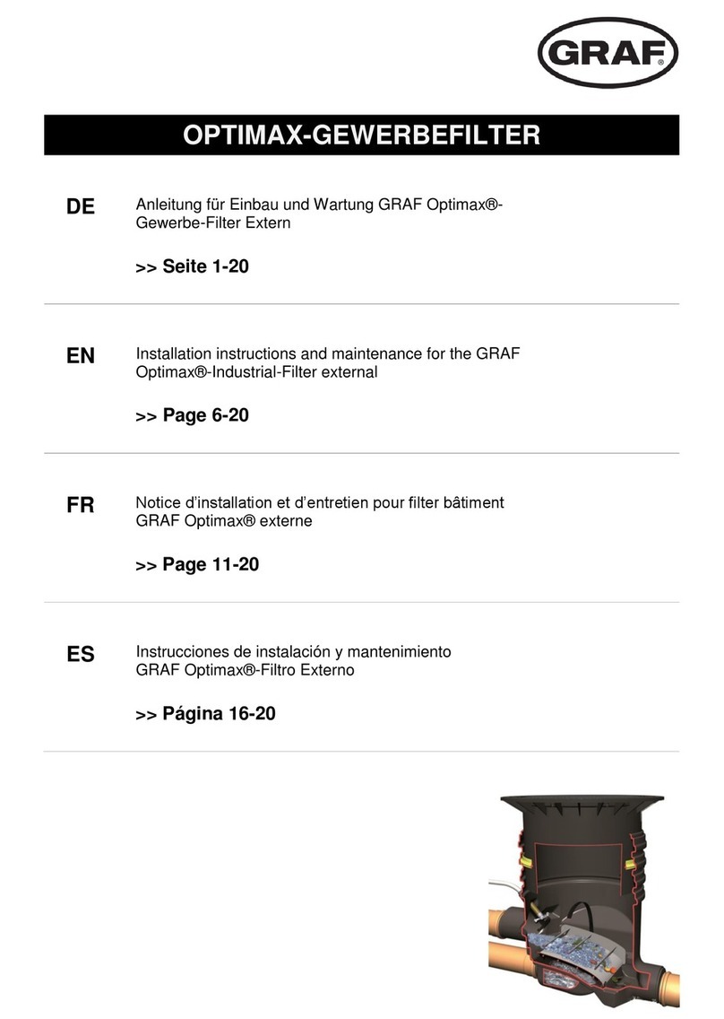
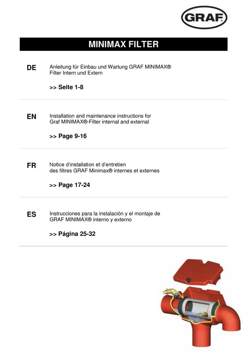
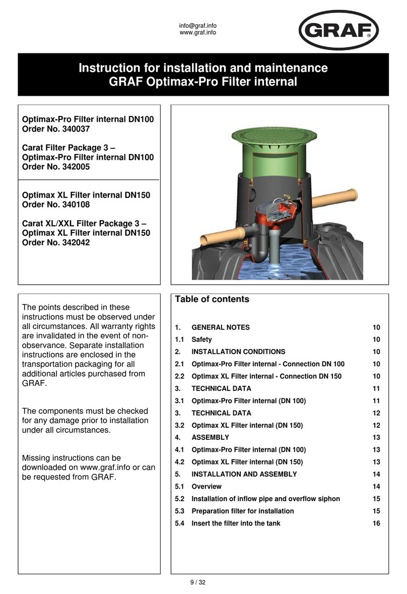
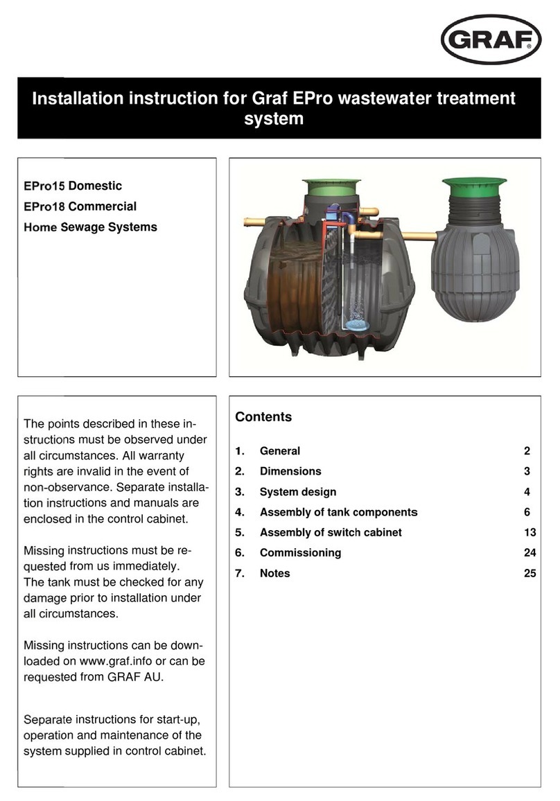
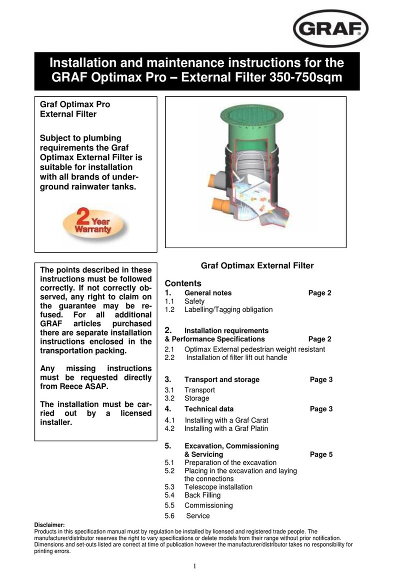
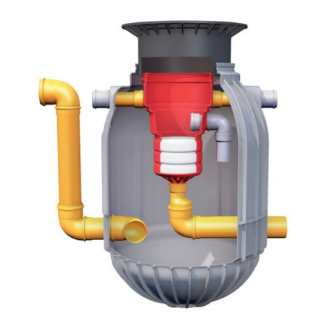
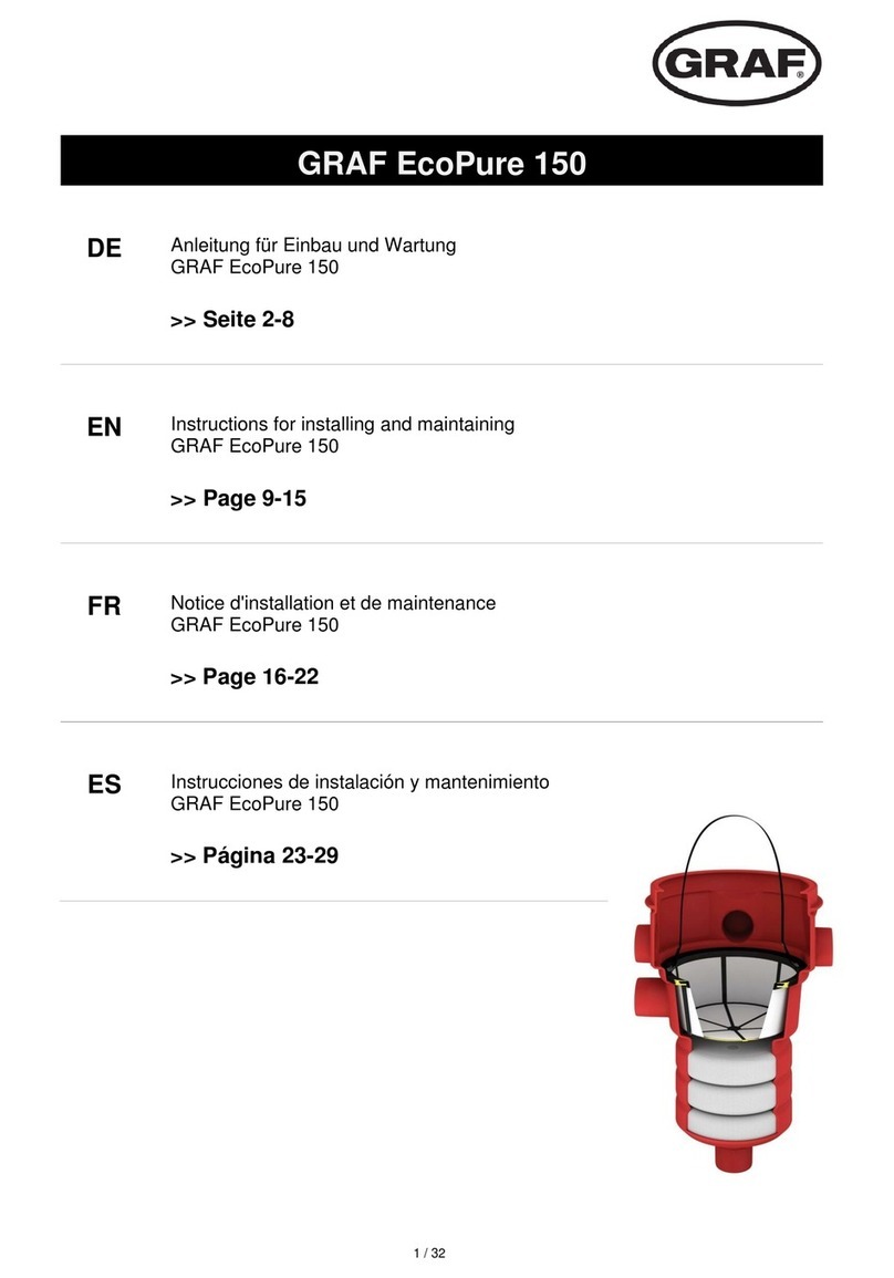
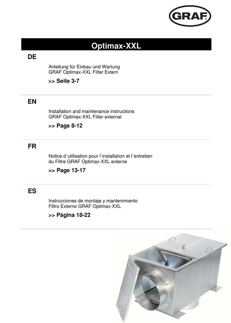
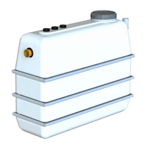
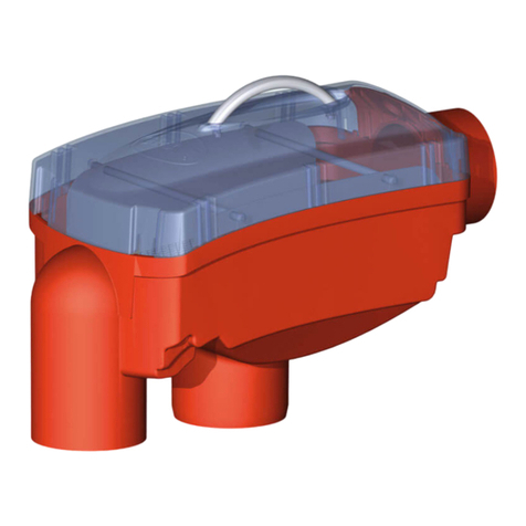
Graf Universal-Filter 3 Series User manual

UNIVERSAL-FILTER 3
DE
Anleitung für Einbau und Wartung
GRAF Universal –Filter 3 extern und intern
>> Seite 3-8
EN
Installation and maintenance instructions for the
GRAF Universal-Filter 3 external and internal
>> Page 9-14
FR
Notice d’installation et d’entretien
Filtre Universel 3 interne & externe Graf
>> Page 15-20
ES
Instrucciones para la instalación y el montaje de los
filtro universal GRAF externo e interno
>> Página 21-26

www.graf.info
2 / 26
Otto Graf GmbH
Kunststofferzeugnisse
Carl-Zeiss-Str. 2-6
DE-79331 Teningen
Tel.: +49 7641 589-66
Fax: +49 7641 589-50
www.graf-online.de

www.graf.info
3 / 26
Anleitung für Einbau und Wartung
GRAF Universal –Filter 3 extern und intern
Universal-Filter 3 extern
für den Grünbereich
Art.-Nr. 340020
Universal-Filter 3 extern
für PKW-befahrene Flächen
Art.-Nr. 340021
Universal-Filter 3 intern DN100
Art.-Nr. 340022
Carat Ausbaupaket 2 –
Universal-Filter 3 intern DN100
Art.-Nr. 342002
Universal-Filter 3 XL intern DN150
Art.-Nr. 340107
Carat XL/XXL Ausbaupaket 2 –
Universal-Filter 3 XL intern DN150
Art.-Nr. 342041
Die in dieser Anleitung beschriebe-
nen Punkte sind unbedingt zu be-
achten. Bei Nichtbeachtung erlischt
jeglicher Garantieanspruch. Für alle
über GRAF bezogenen Zusatzartikel
erhalten Sie separate in der Trans-
portverpackung beiliegende Einbau-
anleitungen.
Eine Überprüfung der Komponenten
auf eventuelle Beschädigungen hat
unbedingt vor der Installation zu
erfolgen.
Fehlende Anleitungen können Sie
unter www.graf.info downloaden
oder bei GRAF anfordern.
Inhaltsübersicht
1. ALLGEMEINE HINWEISE 4
1.1 Sicherheit 4
2. EINBAUBEDINGUNGEN 4
2.1 Universal-Filter 3 extern begehbar 4
2.2 Universal-Filter 3 extern PKW befahrbar 4
2.3 Universal-Filter 3 intern DN100 / Universal-Filter 3
XL intern DN150 4
3. TRANSPORT UND LAGERUNG 4
3.1 Transport 4
3.2 Lagerung 5
4. TECHNISCHE DATEN 5
5. EINBAU UND MONTAGE UNIVERSAL-FILTER 3
EXTERN 6
5.1 Vorbereitung Baugrube 6
5.2 Einsetzen und Anschlüsse legen 6
5.3 Teleskop montieren 6
5.4 Verfüllen 6
6. EINBAU UND MONTAGE UNIVERSAL-FILTER 3
INTERN 7
6.1 Vorbereitung am Filter 7
6.2 Vorbereitung am Tank: 7
6.3 Einsetzen des Filters 7
6.4 Montage Aushebevorrichtung 7
7. INBETRIEBNAHME UND WARTUNG 8

www.graf.info
4 / 26
1. Allgemeine Hinweise
1.1 Sicherheit
Bei sämtlichen Arbeiten sind die einschlägigen Unfallverhütungsvorschriften nach BGV C22 zu beachten.
Besonders bei Begehung der Behälter ist eine 2. Person zur Absicherung erforderlich.
Des Weiteren sind bei Einbau, Montage, Wartung, Reparatur usw. die in Frage kommenden Vorschriften
und Normen zu berücksichtigen. Hinweise hierzu finden Sie in den dazugehörigen Abschnitten dieser
Anleitung.
Bei sämtlichen Arbeiten an der Anlage bzw. Anlageteilen ist immer die Gesamtanlage außer Betrieb zu
setzen und gegen unbefugtes Wiedereinschalten zu sichern.
Der Deckel ist stets, außer bei notwendigen Arbeiten am Filter, verschlossen zu halten, ansonsten be-
steht höchste Unfallgefahr. Der Sitz des Deckels ist regelmäßig zu kontrollieren.
Die Firma GRAF bietet ein umfangreiches Sortiment an Zubehörteilen, die alle aufeinander abgestimmt
sind und zu kompletten Systemen ausgebaut werden können. Die Verwendung anderer Zubehörteile
kann dazu führen, daß die Funktionsfähigkeit der Anlage beeinträchtigt und die Haftung für daraus ent-
standene Schäden aufgehoben wird.
2. Einbaubedingungen
2.1 Universal-Filter 3 extern begehbar
Der Filter mit Teleskop grün und PE-Deckel grün darf nur in nicht befahrenem Grünbereich instal-
liert werden.
Die kurzfristige Belastung der begehbaren PE-Abdeckungen beträgt max. 150 kg, die langfristige
Flächenbelastung max. 50 kg.
Die maximale Einbautiefe bis Filtersohle beträgt 1050 mm.
Anschließbare Dachfläche bei Anschluss an DN 100 = 350 m², bei DN 150 = 500 m².
2.2 Universal-Filter 3 extern PKW befahrbar
Durch die Verwendung des Teleskopaufsatzes (Anthrazit) und der Gussabdeckung Klasse B
nach DIN EN 124 kann der Filter unter PKW befahrenen Flächen installiert werden. Der Filter darf
auf keinen Fall unter LKW befahrenen Flächen eingebaut werden. (siehe Punkt 5.3.2).
Die Erdüberdeckung über dem Zulaufrohr beträgt mind. 450 mm, die max. Einbautiefe bis Filter-
sohle beträgt 1050 mm.
Anschließbare Dachfläche bei Anschluss an DN 100 = 350 m², bei DN 150 = 500 m².
2.3 Universal-Filter 3 intern DN100 / Universal-Filter 3 XL intern DN150
Der Filter ist geeignet für den Einbau in einem Vorschacht oder einer Zisterne.
Höhenunterschied zwischen Zulauf und Ablauf beträgt 275 mm.
Der Filter darf nicht direkt im Erdreich installiert werden.
Anschließbare Dachfläche bei Anschluss an DN 100 = 350 m², bei DN 150 = 500 m².
3. Transport und Lagerung
3.1 Transport
Während des Transportes sind die Filter gegen Verrutschen und Herunterfallen zu sichern. Werden die
Filter zum Transport mit Spanngurten gesichert, ist zu gewährleisten, dass der Filter unbeschädigt bleibt.
Beanspruchungen durch Stöße sind unbedingt zu vermeiden. Auf keinen Fall dürfen die Filter über den
Untergrund gerollt oder geschleift werden.

www.graf.info
5 / 26
3. Transport und Lagerung
3.2 Lagerung
Eine notwendige Zwischenlagerung der Filter muss auf einem geeigneten, ebenen Untergrund erfolgen.
Während der Lagerung muss eine Beschädigung durch Umwelteinflüsse oder Fremdeinwirkung vermie-
den werden.
4. Technische Daten
Universal-Filter 3 extern
Universal-Filter 3 intern –Anschluss DN 100
485
466
122
570
DN 100
Ø500
Universal-Filter 3 XL intern –Anschluss DN 150
485
484
97
535
DN 150
Ø500

www.graf.info
6 / 26
5. Einbau und Montage Universal-Filter 3 extern
5.1 Vorbereitung Baugrube
Damit ausreichend Arbeitsraum vorhanden ist und der Filter gleichmäßig verdichtet werden kann, muss
die Grundfläche der Baugrube die Filtermaße auf jeder Seite um 50 cm überragen. Die Böschung ist
nach DIN 4124 anzulegen. Der Baugrund muss waagerecht und eben sein. Die Tiefe der Grube muss so
bemessen sein, dass die Einbautiefe bis Filtersohle maximal 1050 mm beträgt. Als Unterbau wird eine
Schicht verdichteter Rundkornkies (Körnung 8/16 nach DIN 4226 –1), Dicke ca. 10 cm, aufgetragen.
Wichtig: Die Standfläche für den Filter muss absolut waagerecht sein, um eine optimale Funktion zu
gewährleisten.
5.2 Einsetzen und Anschlüsse legen
Der Filter wird in die vorbereitete Grube eingesetzt und mit den entsprechenden Leitungen verbunden. Es
ist darauf zu achten, dass alle Leitungen mit einem Gefälle in Fliesrichtung von mind. 1% ohne Durchbie-
gungen verlegt werden. Der Notüberlauf muss angeschlossen werden, um einen Rückstau in die Zulei-
tung zu vermeiden.
Wichtig: DIN 1986 ist unbedingt zu beachten, d.h. Durchmesser Zulauf = Durchmesser Ablauf.
5.3 Teleskop montieren
5.3.1 Teleskop begehbar
Das Teleskop wird von oben in das Filtergehäuse ein-
geschoben. Bei Grubentiefen < 930 mm muss das
Teleskop und ggf. das Filtergehäuse gekürzt werden.
Es ist unbedingt darauf zu achten, dass die Zuleitung
im endgültig eingebauten Zustand nicht vom Teleskop
ganz oder teilweise verschlossen wird. Vor dem Ein-
schieben wird die Profildichtung in die Dichtnut des
Gehäuses eingesetzt. Das Teleskop, sowie die Dich-
tung müssen mit der mitgelieferten Schmierseife (kei-
ne Schmierstoffe auf Mineralölbasis verwenden) groß-
zügig eingerieben werden.
Achtung: Trocknet die Schmierseife an lässt sich das Teleskop nur noch sehr schwer bewegen und es
besteht die Gefahr, dass die Dichtung aus der Dichtnut rutscht. Vor dem Verfüllen muss die Dichtung auf
ihren korrekten Sitz überprüft werden. Das Teleskop muss ausreichend unterfüttert werden, so dass sich
Kräfte auf keinen Fall auf das Gehäuse übertragen können.
5.3.2 Teleskop PKW-befahrbar
Das Teleskop wie in Punkt 5.3.1 montieren. Um die PKW-Befahrbarkeit zu gewährleisten muss unter dem
Teleskopkragen mit Magerbeton unterfüttert werden. Die anzufüllende Betonschicht muss mind. 20 cm
breit und ca. 3 cm dick sein.
Achtung: Unbedingt die Stahl-Gussabdeckung verwenden. Verkehrslasten von LKW sind nicht zulässig.
Das Teleskop muss ausreichend unterfüttert werden, so dass sich Kräfte auf keinen Fall auf das Gehäu-
se übertragen können.
5.4 Verfüllen
Vor und während des Verfüllens muss die waagerechte Lage des Filters unbedingt kontrolliert werden.
Die Filterumhüllung wird mit Rundkornkies (Körnung 8/16 nach DIN 4226-1) in einer Breite von ca. 30 cm
lagenweise hergestellt. Die einzelnen Lagen werden in einer Höhe von 30 cm aufgetragen und anschlie-
ßend mit leichtem Verdichtungsgerät (Handstampfer o. ä.) verdichtet. Beim Verdichten ist eine Beschädi-
gung des Filtergehäuses zu vermeiden. Damit keine Kräfte auf das Filtergehäuse übertragen werden
muss das Teleskop gut unterfüttert und eingerüttelt werden. (bei PKW befahrenen Flächen Punkt 5.3.2
beachten) Anschließend wird der Deckel aufgesetzt und kindersicher verschlossen (Punkt 1.1 ist zu be-
achten). Die Verschraubung am Deckel ist so fest anzuziehen, dass sie von einem Kind nicht ge-
öffnet werden kann!
www.graf.info
7 / 26
6. Einbau und Montage Universal-Filter 3 intern
6.1 Vorbereitung am Filter
Vor Installation im Tank muss der Filter, wie in nebenstehender Abbildung gezeigt, vorbereitet werden.
Länge des HT/KG-Verbindungsrohres (bauseits zu stellen) vom Filter zum Zulauftopf:
Carat Volumen
(Liter)
Universal-Filter 3 An-
schluss DN 100*
Universal-Filter 3 XL An-
schluss DN 150*
2.700
1274 mm
1308 mm
3.750
1454 mm
1498 mm
4.800
1684 mm
1728 mm
6.500
1974 mm
2008 mm
8.500
1957 mm
1991 mm
10.000
2157 mm
2191 mm
ab 16.000
2417 mm
2451 mm
* (+ / - 10 mm)
6.2 Vorbereitung am Tank:
Der Siphon wird in die unterste Dichtung (3) des Tankdomes einge-
setzt. Der Zulauf wird an der seitlichen Öffnung (1) montiert, dabei
wird das Rohr von außen nach innen geführt. Der Notüberlauf (2)
wird oberhalb vom Siphon (3) von innen nach außen eingeschoben.
Wichtig: Der Dichtring aus der HT –Rohr Muffe des Notüberlaufs
(2) muss entfernt werden.
6.3 Einsetzen des Filters
Die Spannfixmanschette wird über das am Tankdom montierte Zulauf-
rohr geschoben. Anschließend wird der vorbereitete Filter von oben
durch den Tankdom geführt, in den Notüberlauf gesteckt und mittels
der Spannfixmanschette am Zulaufrohr angeschlossen. Es handelt
sich hierbei um eine Stoß-auf-Stoß Verbindung, d. h. ohne Muffe.
6.4 Montage Aushebevorrichtung
Die Dichtung vom Filterkorb abziehen und den Metallwinkel der Aus-
hebevorrichtung wie abgebildet über den Rand schieben.
Anschließend die Dichtung über den Rand und den Metallwinkel zu-
rückstülpen.

www.graf.info
8 / 26
Otto Graf GmbH –Carl-Zeiss-Str. 2-6 –DE-79331 Teningen –Tel.: +49 7641 589-0 –Fax: +49 7641 589-50
GRAF Distribution S.A.R.L –45, route d´Ernolsheim –FR-67120 Dachstein Gare –Tél.:+33 388 49-7310 –Fax: +33 388 49-3280
GRAF Iberica Tecnología del Plástico S.L. –Marquès Caldes de Montbui, 114 –ES-17003 Girona –Tel.: +34 972 913767 –Fax: +34 972 913766
GRAF UK Ltd –Target House –Thorpe Way Ind. Estate –Banbury –Oxfordshire –UK-OX16 4SP –Tel.: +44 1608 661-500 –Fax: +44 1295 211333
2015-09
7. Inbetriebnahme und Wartung
Die Entnahmevorrichtung muss vor Inbetriebnahme und nach jeder Wartung im 90° Winkel zum Zulauf
ausgerichtet werden, damit sich grobe Schmutzteile nicht am Griff verfangen. Der Siebeinsatz wird zur
Reinigung entnommen, dabei den Korb mit Wasser gründlich reinigen bis alle Poren geöffnet sind. Es
empfiehlt sich die Reinigung alle 4 - 5 Wochen (im Herbst durch starken Laubanfall auch öfter), je nach
Schmutzanfall, vorzunehmen.
Der Siebkorb muss nach jeder Reinigung beim Einsetzen leicht nach unten gedrückt werden, damit die
umlaufende Dichtung passgenau sitzt.
Bei jeder Wartung muss der Überlaufsiphon kontrolliert und bei Bedarf gespült werden.

www.graf.info
9 / 26
Installation and maintenance instructions for the
GRAF Universal-Filter 3 external and internal
Universal-Filter 3 external
for green areas
Order No.: 340020
Universal-Filter 3 external
for areas traversed by light traffic
Order No.: 340021
Universal-Filter 3 internal DN100
Order No.: 340022
Carat filter package 2 –
Universal-Filter 3 internal DN100
Order No.: 342002
Universal-Filter 3 XL internal DN150
Order No.: 340107
Carat XL/XXL filter package 2 –
Universal-Filter 3 XL internal DN150
Order No.: 342041
The points described in these in-
structions must be observed under
all circumstances. All warranty rights
are invalidated in the event of non-
observance. Separate installation
instructions are enclosed in the
transportation packaging for all addi-
tional articles purchased from
GRAF.
The components must be checked
for any damage prior to installation
under all circumstances.
Missing instructions can be down-
loaded on www.graf.info or can be
requested from GRAF.
Table of contents
1. GENERAL NOTES 10
1.1 Safety 10
2. INSTALLATION CONDITIONS 10
2.1 Universal-Filter 3 pedestrian weight resistant 10
2.2 Universal-Filter 3 external for light traffic 10
2.3 Universal-Filter 3 internal DN100 / Universal-Filter 3
XL internal DN150 10
3. TRANSPORT AND STORAGE 10
3.1 Transport 10
3.2 Storage 11
4. TECHNICAL DATA 11
5. ASSEMBLY AND INSTALLATION OF THE
UNIVERSAL-FILTER 3 EXTERNAL 12
5.1 Preparation of the excavation 12
5.2 Placing in the excavation and laying the connections 12
5.3 Telescope installation 12
5.4 Filling 12
6. ASSEMBLY AND INSTALLATION OF THE
UNIVERSAL-FILTER 3 INTERNAL 13
6.1 Filter preparation 13
6.2 Preparation on the tank 13
6.3 Installing the Filter 13
6.4 Assembly of the extraction mechanism 13
7. COMMISSIONING AND SERVICE 14

www.graf.info
10 / 26
1. General notes
1.1 Safety
The relevant accident prevention regulations according to BGV C22 must be observed during all work.
Particularly when walking on the tanks, a 2nd person is required to secure the tank.
The relevant regulations and standards must additionally be taken into consideration during installation,
assembly, servicing, repair, etc. Relevant notes can be found in the corresponding sections of these in-
structions.
During all work on the system or parts of the system, the entire system must always be rendered inopera-
ble and secured to prevent unauthorised reactivation.
The tank cover must always remain closed except when working in the tank, otherwise there exists a very
high danger of accidents. The seating and condition of the cover must be checked on a regular basis.
GRAF offers an extensive range of accessories, all of which are designed to match each other and which
can be extended to form complete systems. The use of other accessories may lead to impediments to the
system's functional capability, therefore invalidating liability for resulting damage.
2. Installation conditions
2.1 Universal-Filter 3 pedestrian weight resistant
The Filter with the green telescopic attachment and cover may only be installed in green areas
that are not traversed by traffic.
The amount of short-term load of the polyethylene cover is max. 150 kg, the long-term area load
max. 50 kg
The maximum installation depth to the filter bottom is 1050 mm.
Roof areas provided with a pipe connection of DN 100 = 350 m² and for DN 150 = 500 m².
2.2 Universal-Filter 3 external for light traffic
Through the use of the telescopic attachment (anthracite) and the cast iron cover Class B accord-
ing to DIN EN 124 the filter may be installed in areas traversed by light traffic. Under no circum-
stances are the tanks to be installed in areas traversed by heavy goods vehicles or machinery
(see point 5.3.2)
The earth covering above the inlet supply pipe must be at least 450 mm; the maximum installa-
tion depth to the filter bottom is 1050 mm.
Roof areas provided with a pipe connection of DN 100 = 350 m² and for DN 150 = 500 m².
2.3 Universal-Filter 3 internal DN100 / Universal-Filter 3 XL internal DN150
The Filter is suitable for installation in a pilot shaft or in a cistern.
The difference in height between the supply pipe and outlet is 275 mm
The Filter may not be installed directly in the earth.
Roof areas provided with a pipe connection of DN 100 = 350 m² and for DN 150 = 500 m².
3. Transport and storage
3.1 Transport
During the transport the filter must be well secured against slipping or falling. If the Filter is to be secured
for transportation with webbing straps, it is to be ensured that the filter remains undamaged.
Stress and excess loading caused by impact are to be avoided. Under no circumstances is the filter to be
rolled or slid over the ground surface.

www.graf.info
11 / 26
3. Transport and storage
3.2 Storage
Any necessary temporary storage of the filter must be on an appropriate level surface without sharp ob-
jects. During the storage it is important to avoid damage caused by the surrounding environment or for-
eign objects.
4. Technical data
Universal-Filter 3 external
Universal-Filter 3 internal –Connection DN 100
485
466
122
570
DN 100
Ø500
Universal-Filter 3 XL internal –Connection DN 150
485
484
97
535
DN 150
Ø500

www.graf.info
12 / 26
5. Assembly and installation of the Universal-Filter 3 external
5.1 Preparation of the excavation
So that sufficient working room is available and the filter can be evenly embedded, the surface area of the
excavation should exceed the filter dimensions on all sides by approximately 50 mm. The excavation
slope is according to DIN 4124. The installations excavation must be level and smooth. The depth of the
excavation must be measured so that the final installation depth of the filter bottom is a maximum
1050 mm. As an under surface for setting down, a layer of smooth sand with a grain size of 8/16 accord-
ing to DIN 4226 –1 and a layer depth of approximately 10 mm should be used.
Important: The setting down surface for the filter must be absolutely level to ensure an optional perfor-
mance.
5.2 Placing in the excavation and laying the connections
The filter is installed in the prepared excavation and is then connected to the relevant pipes etc. Attention,
it is important to note that all the pipes to be installed have a must have a gradient of at least 1% in the
flow direction without sagging or bending downward. An emergency run-off must also be connected so
that a congestion or back surge may be avoided.
Important: DIN 1986 must be followed, therefore the diameter of the supply pipe = the diameter of the
run-off pipe.
5.3 Telescope installation
5.3.1 Telescope pedestrian resistant
The telescope is pressed into the filter housing from above.
For excavation depths < 930 mm the telescopic attachment
and in some circumstances, the filter housing must be short-
ened. It is important to pay attention that the inlet pipe is not
obstructed in any way by the telescope when installed. Be-
fore pushing in the telescope the profiled sealing ring is
placed in the housings recess. The telescope and the seal-
ing ring must be thoroughly coated with the lubricating soap
included in the delivery (use no lubrication that is mineral oil
based).
Attention: If the lubricating soap becomes dry and the telescope becomes difficult to move then there is
the danger that the sealing ring will be forced out of its recess. Before filling, the sealing ring must be
checked once again that it is seated correctly in position. The telescope must be sufficiently embedded
and supported that no forces are transferred to the housing.
5.3.2 Telescope suitable for light traffic
The telescope is installed as in Point 5.3.1. To ensure the function in areas traversed by light traffic, the
telescope must be embedded around the collar with lean mixed concrete. The concrete encasement must
be uninterrupted, 20 cm wide and approximately 30 cm deep.
Attention: It is important to use the cast steel cover. Transport vehicle weight of heavy goods vehicles
and machinery is not permitted. The telescope must be sufficiently embedded and supported that no
forces are transferred to the housing.
5.4 Filling
Important: Before and during the filling, the horizontal position of the filter must be checked. The length-
wise embedding of the filter is with smooth sand with a grain size of 8/16 according to DIN 4226 –1 with
a width of approximately 30 cm. Each layer is to be of no more than 30 cm and must be tamped down
lightly with a compacting machine or hand held tamper. Care must be taken during the embedding to
ensure the filter is not damaged. To ensure that no forces are applied to the filter housing, the telescope
must be well embedded and compacted. (For areas traversed by light traffic see point 5.3.2) Finally, the
cover is set in place and secured so that it is child proof (point 1.1must be followed). The screws holding
down the cover are to be made so tight that they can not be removed and the cover opened by a
child!

www.graf.info
13 / 26
6. Assembly and installation of the Universal-Filter 3 internal
6.1 Filter preparation
Before the installation in the tank, the filter must be prepared as shown in the adjacent depiction.
Length of the HT/canalisation pipe –connections (completed on site) from the filter to the inflow pot:
Carat volume
(liter)
Universal-Filter 3
Connection DN 100*
Universal-Filter 3 XL Con-
nection DN 150*
2.700
1274 mm
1308 mm
3.750
1454 mm
1498 mm
4.800
1684 mm
1728 mm
6.500
1974 mm
2008 mm
8.500
1957 mm
1991 mm
10.000
2157 mm
2191 mm
from 16.000
2417 mm
2451 mm
* (+ / - 10 mm)
6.2 Preparation on the tank
The siphon is installed in the lowest seal (3) of the tank dome.
The inlet pipe is mounted on the side opening (1) the pipe is
inserted from the outside. The emergency overflow (2) is in-
stalled above the siphon (3) and is installed by pushing through
from the inside.
Important: The sealing ring from the HT –pipe coupling of the
emergency overflow (2) must be removed.
6.3 Installing the Filter
The fixing collar is pushed over the inlet pipe that is mounted on the
tanks’ dome. Finally the prepared filter assembly is placed into the
tank dome from above then connected with the emergency overflow
and inlet pipe using the fixing collar. In this case it is a butt joint that
requires no collar.
6.4 Assembly of the extraction mechanism
Remove the seal from the filter basket and push the metal angle of the
lift out mechanism over the rim as shown in the picture.
Finally place the seal over the rim and pull back the metal angle.

www.graf.info
14 / 26
Otto Graf GmbH –Carl-Zeiss-Str. 2-6 –DE-79331 Teningen –Tel.: +49 7641 589-0 –Fax: +49 7641 589-50
GRAF Distribution S.A.R.L –45, route d´Ernolsheim –FR-67120 Dachstein Gare –Tél.:+33 388 49-7310 –Fax: +33 388 49-3280
GRAF Iberica Tecnología del Plástico S.L. –Marquès Caldes de Montbui, 114 –ES-17003 Girona –Tel.: +34 972 913767 –Fax: +34 972 913766
GRAF UK Ltd –Target House –Thorpe Way Ind. Estate –Banbury –Oxfordshire –UK-OX16 4SP –Tel.: +44 1608 661-500 –Fax: + 44 1295 211333
2015-09
7. Commissioning and service
Before commissioning and at every inspection, the lifting out mechanism must be positioned at 90° to the
inlet so that no large objects such as leaves and twigs can catch on the handle. The straining filter is re-
moved for cleaning and the basket must be thoroughly cleaned with water until all the pores are open. It
is advised to clean every 4 to 5 weeks (more often in autumn due to more leaves and twigs) or according
to requirements.
The filter strainer basket must be lightly pressed into place taking care that the seal sits precisely after
every cleaning.
At the occasion of each inspection, the overflow siphon must be checked and flushed in necessary.

www.graf.info
15 / 26
Notice d’installation et d’entretien
Filtre Universel 3 interne & externe Graf
Filtre Universel 3 externe
Passage piétons
Réf. 340020
Filtre Universel 3 externe
Passage véhicules 2T
Réf. 340021
Filtre Universel 3 interne DN100
Réf. 340022
Carat Pack accessoires n°2 –
Filtre Universel 3 interne DN100
Réf. 342002
Filtre Universel 3 XL interne DN150
Réf. 340107
Carat XL/XXL Pack accessoires n°2 –
Filtre Universel 3 XL interne DN150
Réf. 342041
Afin de garantir le bon fonctionne-
ment et la longévité de votre instal-
lation, il est important de respecter
scrupuleusement les instructions de
mise en place du fabricant. Tout
manquement à ces règles annulera
systématiquement la garantie.
Avant d’installer les components, il
est important de vérifier que celle-ci
n’a pas été endommagée.
Les notices manquantes peuvent
être téléchargées sur www.graf.info
ou être demandées auprès de la
société GRAF.
Sommaire
1. GÉNÉRALITÉS 16
1.1 Sécurité 16
1.2 Marquage 16
2. INSTALLATION 16
2.1 Filtre Universel 3 externe - passage piétons 16
2.2 Filtre universel 3 externe - passage véhicules 16
2.3 Filtre Universel 3 interne DN100 / Filtre Universel 3 XL
interne DN150 16
3. ENLEVEMENT ET STOCKAGE 17
3.1 Enlèvement 17
3.2 Stockage 17
4. SPECIFICATIONS TECHNIQUES 17
5. INSTALLATION ET MONTAGE DU FILTRE UNIVERSEL
3 EXTERNE 18
5.1 Excavation 18
5.2 Pose et branchement 18
5.3 Montage de la rehausse télescopique 18
5.4 Remblaiement 19
6. INSTALLATION ET MONTAGE DU FILTRE UNIVESEL 3
INTERNE 19
6.1 Préparation du filtre 19
6.2 Préparation de la cuve: 19
6.3 Mise en place du filtre 20
6.4 Montage du système de suspension du panier filtrant 20
7. MISE EN SERVICE ET ENTRETIEN 20

www.graf.info
16 / 26
1. Généralités
1.1 Sécurité
Les règles de sécurité doivent impérativement être respectées durant l’installation de la cuve. Durant
l’inspection de la cuve, une 2ème personne doit être présente.
Les instructions d’installation, de montage, d’entretien et de réparation indiquées ci-après doivent être
scrupuleusement respectées.
Durant toute intervention sur la cuve ou les accessoires, l’installation complète doit être mise hors ser-
vice.
Le couvercle de protection provisoire placé sur la cuve lors de la livraison doit immédiatement être rem-
placé par le couvercle définitif double parois en PE ou la rehausse télescopique avec couvercle en PE.
Seuls les couvercles GRAF doivent être utilisés.
En dehors de l’entretien de la cuve, le couvercle doit impérativement être verrouillé. Pour des raisons de
sécurité, le bon positionnement du couvercle doit être vérifier régulièrement.
La société GRAF vous propose une large gamme d’accessoires d’une grande compatibilité. L’utilisation
d’autres accessoires peut contribuer à un mauvais fonctionnement de l’installation. Les dommages subis
dans ce cas ne sont pas garantis.
1.2 Marquage
Afin d’éviter toute confusion, toutes les canalisations et sorties d’eau de pluie doivent être signalées par
la mention écrite ou en image « Eau non potable ». Toutes les sorties doivent être équipées de vannes
« sécurité enfant ».
2. Installation
2.1 Filtre Universel 3 externe - passage piétons
Il est interdit de circuler avec un véhicule sur le Filtre Universel 3 Externe –passage piétons –re-
hausse télescopique couleur vert, couvercle PE couleur vert.
Charge maximum autorisée à cours terme du couvercle double parois en PE : 150 kg ; à long
terme : 50 kg.
Profondeur maximale d’installation (bord inférieur du filtre) : 1050 mm
Convient aux surfaces de toiture 350 m² en DN 100 et 500 m² en DN 150.
2.2 Filtre universel 3 externe - passage véhicules
Possibilité de circuler sur la rehausse télescopique couleur noir avec couvercle en fonte pour les
véhicules de la catégorie B d’un poids inférieur ou égal à 2 tonnes.
En aucun cas ce filtre ne doit être installé dans un lieu de passage de camions.
La hauteur de recouvrement au-dessus du tuyau PVC d’arrivée d’eau de pluie dans le filtre doit
être au minimum de 450 mm.
Profondeur maximale d’installation (bord inférieur du filtre) : 1050 mm
Convient aux surfaces de toiture 350 m² en DN 100 et 500 m² en DN 150.
2.3 Filtre Universel 3 interne DN100 / Filtre Universel 3 XL interne DN150
Filtre adapté pour la mise en place dans une cuve ou un regard de visite.
Entre-axe: 275mm
Ne pas enterrer le filtre dans le sol.
Convient aux surfaces de toiture 350 m² en DN 100 et 500 m² en DN 150.

www.graf.info
17 / 26
3. Enlèvement et stockage
3.1 Enlèvement
Durant le transport, les filtres doivent être sécurisés afin de ne pas être endommagés et ne pas glisser ou
tomber du camion. Si les filtres sont arrimés avec des sangles, il faut s’assurer que celles-ci n’ont pas
endommagé les filtres
Manipuler avec précaution et éviter tout coup. En aucun cas les filtres ne doivent être roulés ou traînés
sur le sol.
3.2 Stockage
Le stockage des filtres doit se faire sur un sol adapté, plat et sans objet pointu. Durant le stockage veiller
à ce qu’aucun élément extérieur ou environnemental n’endommage les filtres.
4. Spécifications techniques
Filtre Universel 3 externe
Filtre Universel 3 interne –Connexion DN 100
485
466
122
570
DN 100
Ø500
Filtre Universel 3 XL interne –Connexion DN 150
485
484
97
535
DN 150
Ø500

www.graf.info
18 / 26
5. Installation et montage du filtre Universel 3 externe
5.1 Excavation
Pour faciliter une bonne mise en place, prévoir une excavation minimum de 50 cm autour du filtre. Ne pas
placer le filtre au pied d’une pente ou d’un talus : le terrain doit être plan.
Profondeur de l’excavation : le bord inférieur du filtre doit être à une profondeur maximum de 1050 mm.
Disposer au fond de l’excavation une couche de gravier 8/16 d’environ 10 cm recouvert d’une couche de
sable fin d’environ 5 cm.
Attention ! Pour garantir le bon fonctionnement du filtre, celui-ci doit être posé sur un fond parfaitement
horizontal.
5.2 Pose et branchement
Poser le filtre dans l’excavation préparée (selon § 5.1) et effectuer les branchements avec les tuyaux PVC
(arrivée eau de pluie de la gouttière et évacuation vers la cuve et le trop-plein de sécurité). Utiliser du
tuyau d’assainissement DN100 avec manchon DN 100 à joint à lèvres.
Ces tuyaux PVC doivent être posés avec une déclinaison de minimum 1 %.
Il est impératif d’effectuer le branchement du trop-plein afin d’éviter un retour vers l’arrivée de l’eau de
pluie.
Attention ! Ø arrivée = Ø évacuation
5.3 Montage de la rehausse télescopique
Attention ! Ne jamais graisser les joints d’étanchéité avant leur positionnement ! Ils risquent de
sortir de leur cavité lors de la pose de la rehausse.
5.3.1 Rehausse télescopique passage piétons
Faire glisser la rehausse télescopique dans le corps du filtre.
Dans le cas d’une excavation < à 930 mm la rehausse et éven-
tuellement le corps du filtre doivent être raccourcis.
Attention ! Dans ce cas vérifier que le manchon d’arrivée d’eau
de pluie ne soit pas partiellement ou entièrement obstrué par la
rehausse.
Avant de positionner la rehausse, insérer le joint d’étanchéité
dans la rainure du corps du filtre. Enduire ensuite généreuse-
ment le joint et la rehausse avec la graisse blanche (ne pas
utiliser de graisse à base d’huile minérale, trop agressive pour le joint).
Attention ! Ne pas laisser sécher la graisse blanche : le positionnement de la rehausse sera plus difficile
et le joint EPDM risque de se déloger de la rainure et l’étanchéité ne sera plus garantie.
Vérifier le bon positionnement du joint d’étanchéité avant de remblayer autour de la rehausse. Bien tasser
le remblai autour de la rehausse, de sorte qu’aucune pression extérieure ne modifie le positionnement de
la rehausse télescopique.
5.3.2 Rehausse télescopique passage véhicules
Installer la rehausse comme indiqué dans le § 5.3.1. Dans le cas ou des voitures circulent au-dessus du
filtre universel 3 externe, il est impératif d’installer une dalle de répartition en béton maigre autour de la
rehausse, au minimum sur une largeur de 20 cm et une hauteur de 30 cm.
Attention ! Utiliser impérativement le couvercle en fonte. Uniquement prévu pour passage véhicules 2
tonnes.
Vérifier le bon positionnement du joint d’étanchéité avant de remblayer autour de la rehausse. Bien tasser
le remblai autour de la rehausse, de sorte qu’aucune pression extérieure ne modifie le positionnement de
la rehausse télescopique.

www.graf.info
19 / 26
5. Installation et montage du filtre Universel 3 externe
5.4 Remblaiement
Vérifier le positionnement horizontal du filtre avant et pendant le remblaiement. Remblayer avec du gra-
vier 8/16 sur environ 30 cm autour du filtre, par couches successives de 30 cm de hauteur. Tasser avec
les pieds.
Attention ! Ne jamais tasser la terre avec un engin de terrassement.
Veillez à ne pas endommager le filtre.
Bien tasser le remblai autour de la rehausse, de sorte qu’aucune pression extérieure ne modifie le posi-
tionnement de la rehausse télescopique. (pour rehausse télescopique passage véhicules, voir § 5.3.2).
Attention ! Positionner et verrouiller le couvercle (sécurité enfant). Serrez suffisamment le boulon
afin qu’un enfant ne puisse l’ouvrir !
6. Installation et montage du filtre Univesel 3 interne
6.1 Préparation du filtre
Avant sa mise en place, le filtre doit être préparé comme le montre le schéma suivant.
Le tuyau anti-remous en PVC (fournis) reliant le filtre au manchon percé ou au sabot et tuyau :
Carat volume
(litre)
Filtre Universel 3 Conne-
xion DN 100*
Filtre Universel 3 XL Con-
nexion DN 150*
2.700
1274 mm
1308 mm
3.750
1454 mm
1498 mm
4.800
1684 mm
1728 mm
6.500
1974 mm
2008 mm
8.500
1957 mm
1991 mm
10.000
2157 mm
2191 mm
de 16.000
2417 mm
2451 mm
* (+ / - 10 mm)
6.2 Préparation de la cuve:
Brancher le siphon dans l’ouverture inférieure du dôme de
la cuve (3). Le tuyau d’arrivée se monte sur l’ouverture
latérale (1), en l’introduisant de l’extérieur vers l’intérieur
du dôme. Le trop-plein de sortie du filtre (2) se branche
dans l’ouverture supérieure à celle du siphon, en
l’introduisant de l’intérieur vers l’extérieur du dôme.

www.graf.info
20 / 26
Otto Graf GmbH –Carl-Zeiss-Str. 2-6 –DE-79331 Teningen –Tel.: +49 7641 589-0 –Fax: +49 7641 589-50
GRAF Distribution S.A.R.L –45, route d´Ernolsheim –FR-67120 Dachstein Gare –Tél.:+33 388 49-7310 –Fax: +33 388 49-3280
GRAF Iberica Tecnología del Plástico S.L. –Marquès Caldes de Montbui, 114 –ES-17003 Girona –Tel.: +34 972 913767 –Fax: +34 972 913766
GRAF UK Ltd –Target House –Thorpe Way Ind. Estate –Banbury –Oxfordshire –UK-OX16 4SP –Tel.: +44 1608 661-500 –Fax: +44 1295 211333
2015-09
6. Installation et montage du filtre Univesel 3 interne
6.3 Mise en place du filtre
Monter la manchette de fixation rapide sur l’arrivée d’eau située en haut du dôme. Pour cela, introduire le
filtre par le haut dans le dôme, brancher sur trop-plein de sortie et fixer le filtre au tuyau d’arrivée d’eau au
moyen de la manchette de fixation rapide. Il s’agit donc d’un montage en bout-à-bout n’utilisant pas de
manchon.
6.4 Montage du système de suspension du panier filtrant
Ecarter le joint du panier filtrant et mettre en place le crochet
métallique du mécanisme de suspension sur le bord du panier
filtrant.
Recouvrez enfin le bord du panier et le crochet métallique avec
le joint.
7. Mise en service et entretien
Positionner le panier dans le corps du filtre.
Attention ! Veiller à ce que l’anse du panier n’obstrue ni le manchon d’arrivée d’eau de pluie, ni le
manchon du trop-plein. Des salissures pourraient rester accrochées à l’anse et empêcher le bon écou-
lement de l’eau de pluie dans le panier. Vérifier régulièrement l’état de propreté du panier. Un nettoyage
s’impose environ toutes les 4 à 5 semaines, en fonction des salissures sur le toit (éventuellement davan-
tage en automne).
Sortir le panier et le nettoyer à l’aide d’un tuyau d’arrosage.
Remettre le panier dans le corps du filtre en le poussant légèrement vers le bas, de sorte que le joint au-
tour du panier soit bien positionné.
Vérifier également le trop-plein de sécurité du filtre et si nécessaire le nettoyer.
Manchette
de
fixation
rapide
This manual suits for next models
7
Table of contents
Languages:
Other Graf Water Filtration System manuals

Graf
Graf Garden Comfort Platin 1500 L User manual

Graf
Graf Optimax-Pro User manual

Graf
Graf EcoPure 200 Instruction Manual

Graf
Graf OPTIMAX Instructions for use

Graf
Graf 340037 Operating and maintenance manual

Graf
Graf MINIMAX Series User manual

Graf
Graf one2clean+ XXL Installation instructions

Graf
Graf MINIMAX 340060 User manual

Graf
Graf one2clean+ XXL User manual

Graf
Graf Optimax-Pro Operating and maintenance manual