Grant SpiraVac WPVKIT5POD Assembly Instructions

1
Grant SpiraVac Pellet Feed System
For Grant SpiraPod Installations
Installation & User Instructions
Part No. DOC.103 Provisional Rev.07 31/07/16

2
EC Declaration of Conformity
In accordance with BS EN ISO/IEC 17050-1:2004
We Grant Engineering (IRL)
Of Crinkle
Birr
Co. Offaly
Ireland
Telephone: 057 912 0089
Fax: 057 912 1060
Email: info@grantengineering.ie
Website: www.grantengineering.ie
Declare that
Equipment: Wood Pellet Vacuum System for Domestic Wood Pellet Boilers
Model Name/Number: Grant BioVac System
In accordance with the following EC Directives:
2006/42/EC Conforms with the requirements of the Machinery Directive.
2006/95/EC Conforms with the safety objectives of the Low Voltage Directive and its
amending Directives
2004/108/EC Conforms with the essential protection requirements of the
Electromagnetic Compatibility Directive and its amending Directives
Has been designed and manufactured to the following Specifications:
EN60335-1:2012 Household and similar electrical appliances. Safety –General
requirements.
EN60335-2-2:2010 Household and similar electrical appliances. Safety. Particular
requirements for vacuum cleaners and water suction cleaning
appliances.
EN55014-1:2006 Electromagnetic Compatibility. Requirements for household appliances.
MCS008 Product Certification scheme requirements - Biomass
Important Note for Installers
After installing the Grant SpiraVac system leave these Installation Instructions with the appliance. Also
leave the Spira Installation and Servicing Instructions, the Spira User Instructions and the SpiraPod
Installation Instructions with the householder.
This appliance is deemed a controlled service and specific regional statutory requirements may be
applicable.

3
Contents
Page
1. Introduction 4
2. Technical Specification
2.1 Kit contents 5
2.2 Technical data 6
3. Description & Operation
3.1 Cyclone unit 7
3.2 Spigot plate 7
3.3 Control box 8
3.4 Auger/vacuum unit 8
3.5 Flexible pellet tubes 9
3.6 Operating sequences 10
4. Installation
4.1 Auger/vacuum unit 14
4.2 Cyclone unit 16
4.3 Control box 19
4.4 Flexible pellet tubes 21
5. Electrical
5.1 General 23
5.2 Connection to pellet hopper 23
5.3 Connection of SpiraVac system to SpiraPod hopper 24
5.4 Connection of control box to Auger/vacuum unit 24
5.5 Wiring diagrams 25
6. Commissioning
6.1 General 28
6.2 Procedure 28
7. Servicing
7.1 Auger/vacuum unit 30
7.2 Flexible pellet tubes 31
8. User Instructions
8.1 Introduction 32
8.2 About the SpiraVac system 32
8.3 Controls 32
8.4 Starting the system 33
8.5 ’24 hour’ operation 33
8.6 Manual operation 34
9. Guarantee 35

4
1. Introduction
These Installation instructions should be read carefully before installing the BioVac system and must be
used in conjunction with the Grant Spira Installation & User instructions supplied with the boiler and the
Grant SpiraPod Installation Instructions. Installation of the Grant Spira boiler, Grant SpiraPod and Grant
BioVac system must only be carried out by a Grant Approved Installer who has successfully completed
the Grant Spira training course.
The Grant BioVac is a vacuum system for conveying wood pellets from a bulk store to the pellet hopper
located adjacent to the Grant Spira boiler in the Grant SpiraPod external enclosure. It is designed
specifically for use with the Grant Spira wood pellet boilers and should not be used with other wood pellet
burning appliances. It is intended to convey 6mm diameter EN Plus A1 (BS EN ISO17225-2:2014) wood
pellets only and should not be used for any other application.
Grant Engineering (UK) Ltd shall not be liable for any injury or damage arising from the incorrect use of
this system. For correct usage, refer to these Installation and User instructions.
Installation of the Grant Spira wood pellet boiler, the Grant SpiraPod external enclosure and the Grant
BioVac vacuum system, must be carried out by a competent person in accordance with all current
legislation, codes of practice and local by-laws relating to the installation of solid fuel burning appliances.
The electrical installation must comply with the requirements of the Electricity at Work Regulations 1989
and BS7671:2008 - IET Wiring Regulations 17th Edition (including all amendments).
All installations of Grant Spira wood pellet boilers must comply with the relevant Building Regulations.

5
2. Technical Specification
2.1 Kit Contents
The Grant SpiraVac system for the Grant SpiraPod is available in 4 different kits, containing the following:
1 x Combined Auger and Vacuum unit
1 x Cyclone unit
1 x Control box
1 x Spigot plate (c/w 2 x spigot connectors)
2 x Flexible connector tubes - 700mm long
8 x ‘Jubilee’ type pipe clips
4 x M5 fixing screws (for Cyclone unit)
Flexible pellet tube - length dependant on kit - see table below
Metal pipe clips (quantity to suit tube length used –see table below)
Installation & User Instructions
NOTE.
The electrical cable required to connect the auger/vacuum unit (located on the bulk pellet store) to the
BioVac system control box (in the SpiraPod) to be supplied by installer.
SpiraVac Kit Ref
No.
Length of flexible pellet tube
(between auger/vacuum unit and
pellet hopper in SpiraPod)
Number and lengths of
tube supplied
Quantity of metal
pipe support clips
WPVKIT5POD
5m
1 x 10m length
10
WPVKIT10POD
10m
2 x 10m length
20
WPVKIT15POD
15m
2 x 15m length
30
WPVKIT20POD
20m
2 x 20m length
40
Figure 2-2. Cyclone unit
Figure 2-1. Auger/vacuum unit

6
2.2 Technical Data
Auger unit
Vacuum unit
Weight
16.4kg
24kg
Supply Voltage
230V 50HZ 1ph 13A fused*
Running Current
8A
Power
1740W
Sound Level
(TBC)
*Refer to Section 5.2 for further details on fuse ratings required
Figure 2-4. Control box
Figure 2-5. Flexible tube

7
3. Description & Operation
The Grant SpiraVac pellet feed system for the Grant SpiraPod consists of the following items
3.1 Cyclone Unit
The cyclone unit is designed to be mounted inside the pellet hopper of the Grant SpiraPod external
enclosure. The SpiraPod pellet hopper is factory fitted with the necessary mounting rails and has a
removable access cover at the rear of the pellet hopper to allow fitting of the cyclone unit. Refer to
Section 4 of these instructions for cyclone unit installation details.
When fitted, the inlet and outlet connections of the cyclone unit will face towards the rear of the pellet
hopper. Two short (700mm long) flexible connector tubes are supplied to connect the cyclone to the two
spigot connections mounted on the inward facing side of the pellet hopper, at the rear of the SpiraPod.
Refer to Figure 3-1.
The cyclone unit is fitted with a counter-balanced trap door at the bottom. This door is drawn closed by
the vacuum generated when the vacuum unit is operating. See Section 3.4 for details on vacuum unit.
When the vacuum unit stops, and the vacuum ceases, the weight of the pellets collected in the cyclone
pushes the door open and the pellets are dropped into the hopper.
The cyclone unit incorporates a proximity switch, mounted on the side of the cyclone. Refer to Figure 3-2.
This is operated when the vacuum produced by the vacuum motor pulls the cyclone trap door closed.
Activation of this switch allows the auger unit (located on the bulk pellet store) to run. Thus the auger
motor can only run when the vacuum motor is operating.
3.2 Spigot Plate
This is designed to provide the VACUUM FLOW and VACUUM RETURN connections on the inward
facing side of the SpiraPod pellet hopper. Refer to Figure 3-3. For details of where and how it is fitted
refer to Section 4.2 of these Installation and User Instructions
Figure 3-1. Cyclone unit inside pellet hopper
Figure 3-2. Proximity switch on cyclone unit

8
3.3 Control Box
The SpiraVac system control box is located remotely from the cyclone unit, mounted on the underside of
the pellet hopper, below the wiring centre at the front of the SpiraPod enclosure. Refer to Figure 3-4.
The control box has two factory-fitted flying leads with pre-wired plug connectors.
The 6-way plug connects the vacuum unit to the SpiraPod pellet hopper. This plug is fitted to the
corresponding 6-way plug connector on the side of the SpiraPod wiring centre (at the front of the
pellet hopper).
The 4-way plug provides the electrical connection for the remote Auger/Vacuum unit. A suitably
sized cable of the required length must be connected between the corresponding 4-way plug
connector (supplied fitted to the plug) and the electrical isolator of the remote auger (mounted on
the bulk pellet store).
The control box has a control panel fitted with a ‘VACUUM SYSTEM’ON/OFF switch and indicator neon.
Refer to Figure 3-5.
Figure 3-5. Vacuum unit control panel
For details on the operation of these controls, refer to the User Instructions in Section 8 of these
Installation & User Instructions.
3.4 Auger/Vacuum Unit
The auger/vacuum unit has been designed to be mounted directly onto the Grant bulk pellet store (with
the fixings supplied on the store) using the holes already present around the rectangular outlet opening at
the base of the store. It can also be fitted to other bulk pellet stores by drilling the required holes (using
the auger mounting flange as a template) –refer to Section 4.1.
Figure 3-4. Control box
Figure 3-3. Spigot plate

9
The unit consists of:
a) A 410mm long auger, driven by an electric motor, which delivers pellets from the bottom of the
store into the suction chamber. Refer to Figure 4-2.
b) A Vacuum motor that pulls the air through the cyclone unit (located in the pellet hopper of the
SpiraPod enclosure) via the flexible suction tubes. This transports the pellets from the suction
chamber of the auger/vacuum unit to the cyclone of the pellet hopper.
The auger, vacuum motor and suction chamber are all enclosed under a removable steel cover. This
cover, and the rest of the unit, is lined with acoustic insulation to reduce the noise level from the unit when
in operation. Refer to Figure 3-6.
Air to cool the vacuum motor is drawn in through a vent in the rear of the auger/vacuum unit and
exhausted through an opening in the bottom of the enclosure.
IMPORTANT
Ensure that the cooling vent at the rear of the auger/vacuum unit is not obstructed at any time.
Two steel connection spigots, on the vacuum motor and auger/suction chamber, are provided inside the
auger/vacuum unit for connection of the vacuum system flexible tubes. Refer to Figure 3-7.
The cover of the suction chamber is held in place by two nuts. Refer to Refer to Figure 3-7.
A 3-pole 16A isolator is factory fitted to the outside of the auger/vacuum unit for local electrical isolation of
both the auger and vacuum motors when required. This isolator is pre-wired to the auger motor and
vacuum motor. An electrical supply, from the 4-way plug (supplied factory-fitted on a cable from the
BioVac control box), must be connected by the installer to the input of the isolator. Refer to Section 5 for
electrical connection details.
3.5 Flexible Pellet Tubes
Two lengths of flexible pellet tube (supplied with the SpiraVac system kit) are used to connect the
auger/vacuum unit (mounted on the bulk pellet store) to the vacuum flow and return connections at the
rear of the pellet hopper in the SpiraPod enclosure. Refer to Section 4.4. for details.
Two shorter lengths of flexible pellet tube (also supplied with the SpiraVac system kit) are used to connect
the vacuum flow and return connections at the rear of the pellet hopper to the cyclone unit located inside.
Refer to Section 4.2 for details.
Figure 3-7. Auger/vacuum unit –cover removed
Figure 3-6. Auger/vacuum unit –cover fitted

10
The tube supplied is a 50mm diameter reinforced Polyurethane flexible tube with a copper anti-static wire
moulded into the tube wall. When fitting the tube, this wire must be exposed and placed in contact with
the steel connections (on the auger/vacuum and pellet hopper) at each end. Refer to Section 4.4 for
details.
The maximum length of tube between the cyclone unit (inside the pellet hopper of the SpiraPod) and the
auger/vacuum (mounted on the bulk pellet store) is 20 metres (i.e. 2 x 20 metres lengths - one each way).
The maximum rise over that length is 5 metres. No reduction in this maximum allowance is required for
any changes in the height of the tube over the length of run.
Both tubes are secured at each end, to the connections on the vacuum and auger units, using the four
hose clips provided with the kit. Refer to Section 4.3 for details.
Any pellet tubes run against walls MUST be adequately supported at no more that 1 metre centres, and
at either sides of a bend in the tube, using the 50mm metal pipe clips provided.
3.6 Operating Sequences
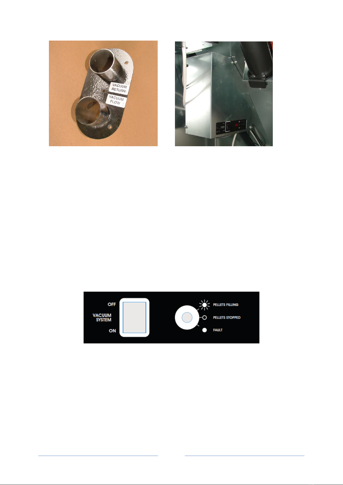
The BioVac system control box has a ‘VACUUM SYSTEM’ ON/OFF switch on the control panel.
When this switch is set to ON –the vacuum system operates in Automatic mode. Refer to
Section 3.6.1 below.
When this switch is set to OFF –the vacuum system operates in Manual mode. Refer to Section
3.6.2 below
3.6.1 Automatic Mode
With the ‘VACUUM SYSTEM’ON/OFF switch set to ON the SpiraVac vacuum system is operational.
In this condition the SpiraVac system will function in one of two different automatic operating modes:
‘Top-up’ mode –to automatically top-up the pellet hopper when the pellet level falls below the
minimum level, as detected by the contents sensor. Once the contents sensor is activated, the
vacuum motor and filling process will automatically start, as detailed below.
‘24 hour’mode –to automatically fill the hopper with pellets, up to the trap door of the vacuum
unit trap door, every 24 hours starting at the time when the ON/OFF switch on the BioVac control
panel is first set to ON.
In both cases the operation of the vacuum system is as follows –Refer to the flow diagram in Figure 3-8.
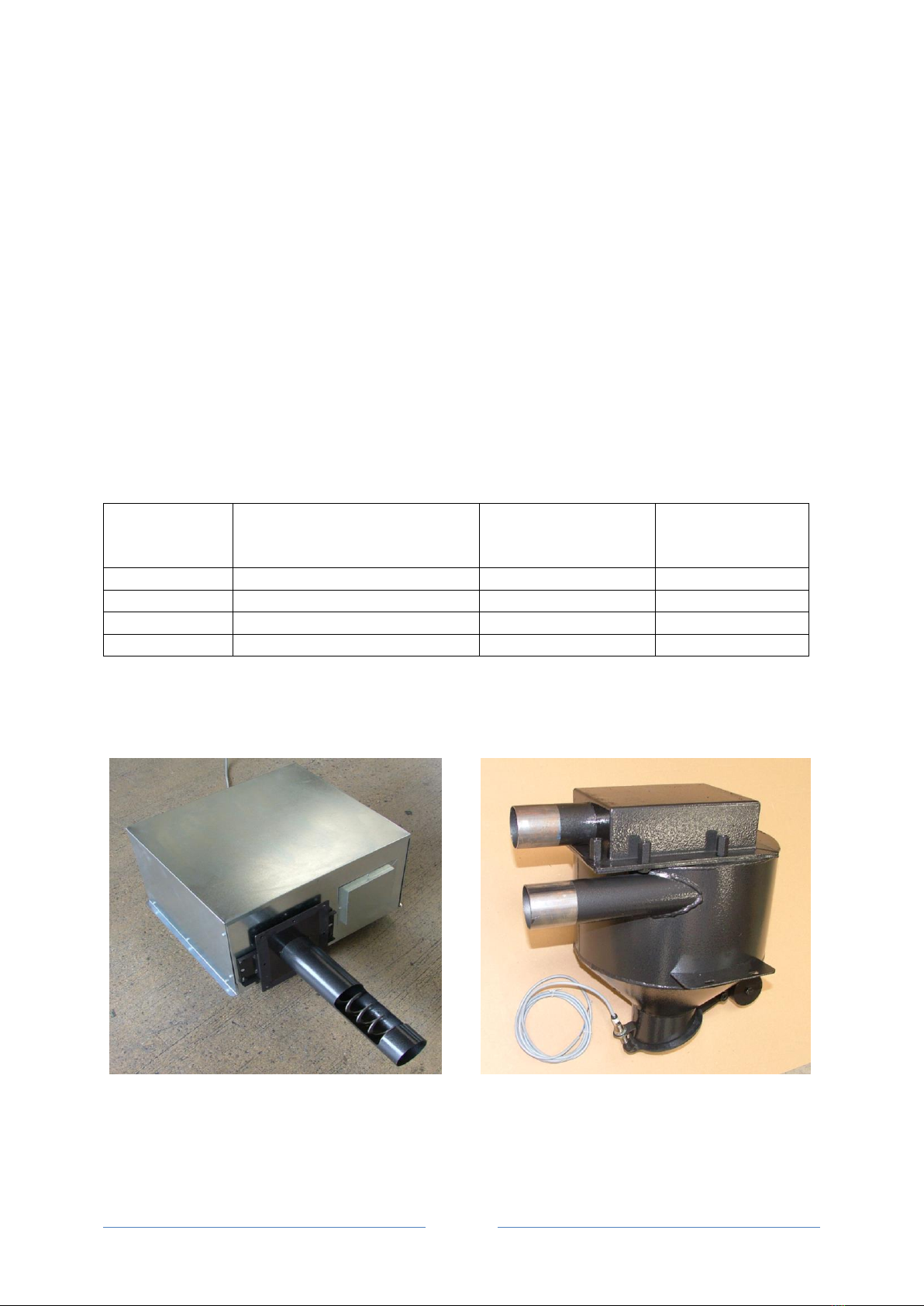
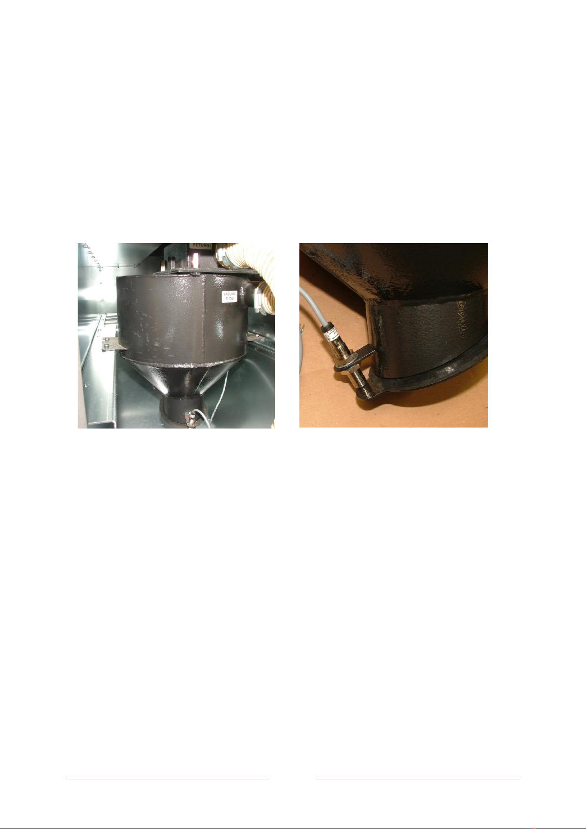
The vacuum motor will start and create a vacuum in the cyclone unit. This pulls closed the trap door at
the base of the cyclone. The proximity switch (mounted on the side of the cyclone) is activated. Power is
supplied to the pellet auger located in the base of the bulk pellet store.
The auger starts and pulls pellets into the suction chamber of the auger unit, from where they are drawn
into and through the flexible suction tube and deposited in the cyclone unit. The red indicator neon on the
SpiraVac system control panel will blink on and off during this process.
The pellet auger runs for 90 seconds and is then automatically switched off. The vacuum motor runs on
for a further 15 seconds after the auger has stopped (to ensure no pellet build up in the tubes) before it
is automatically switched off (i.e. a total vacuum motor running time of 105 seconds).

11
When the vacuum motor stops, the loss of the vacuum allows the weight of the pellets in the cyclone to
open the trap door and the pellets fall into the hopper.
The vacuum system will deliver approximately 6kg of pellets in each operation, and will therefore have to
operate several times to either top up or fill the pellet hopper.
When the ‘VACUUM SYSTEM’ ON/OFF switch is first set to ON
The vacuum system will operate repeatedly, as described above, until the hopper is filled with pellets up
to the level of the trap door of the cyclone unit. In this condition the trap door will be prevented from
closing by the pellets. This is intentional as further operation of the vacuum system is not required with
this amount of pellets in the hopper.
Thereafter the vacuum unit will automatically operate in one of the two following ways
‘Top-up’ mode
The SpiraVac system will only operate in this mode if the level of pellets in the hopper falls below the
minimum level monitored by the contents sensor.
The vacuum system will operate repeatedly to top-up the hopper until it is filled with pellets up to the level
of the trap door of the cyclone unit as on the initial operation of the vacuum system. In this condition the
trap door will be prevented from closing by the pellets.
If the pellet hopper contents sensor has detected a low pellet level and the vacuum system is operating,
but the pellet hopper contents switch is not satisfied after 26 attempts (e.g. due to the bulk pellet store
being empty) then the system will go into ‘fault’ mode.
The indicator neon on the SpiraVac system control panel will remain on constantly. The user can over-ride
this by switching the ‘VACUUM SYSTEM’ switch to OFF and filling the pellet hopper manually (see
Section 3.6.2 –Manual Mode below).
‘24 hour’ mode
In this operating mode the SpiraVac system will only operate after exactly 24 hours has elapsed since the
‘VACUUM SYSTEM’ ON/OFF switch on the SpiraVac control panel was last set to ON.
The vacuum system will operate repeatedly until the hopper is filled with pellets up to the trap door of the
cyclone unit, as on the initial operation of the vacuum system.
It is possible to re-set the time that this ’24 hour’ operation occurs to a more suitable time (e.g. during the
evening) to avoid the automatic operation of the vacuum system during the night time.
To do this, simply switch the ‘VACUUM SYSTEM’switch to OFF, wait about 2 seconds and then back to
ON at the time you wish the ’24-hour’ operation to occur. This time will be automatically stored in the
control system memory and the store will then fill at the same time every day (if required).
NOTE
If the power supply to the SpiraPod and SpiraVac system is interrupted, either deliberately or otherwise
(e.g. a power cut), the built-in timer function will stop for the duration of the power interruption.
Whilst the SpiraVac system will automatically continue to operate in the ’24 hour’ mode when the power is
reconnected, and the original time setting will be remembered, the actual time it will operate to fill the

12
hopper will now be incorrect, i.e. delayed by the duration of the power interruption.
Example: If the ‘24hour’ mode was originally set to operate at 6.00pm every day, but a power cut lasting
1 hour occurred, the ‘24hour’ mode will now operate at 7.00pm after the power is reconnected.
It will therefore be necessary to reset the ‘24 hour’ mode following a power interruption if the original ’24
hour’ mode operating time setting is still required. To do this, simply switch the ‘VACUUM SYSTEM’
switch to OFF, wait for about 2 seconds and then switch back to ON at the time you wish the ’24-hour’
operation to occur.
3.6.2 Manual Mode
With the ‘VACUUM SYSTEM’ switch on the SpiraVac control panel set to OFF, the hopper will function as
if no vacuum system is fitted.
In this setting, the pellet hopper can be fed with bagged pellets for as long as required.
The switched live to the boiler will be interrupted when the weight of pellets in the pellet hopper falls to
the minimum level detected by the contents sensor, and the burner will shut down.
The burner control panel screen on the Spira boiler will show a ‘WAIT BOILER THERMOSTAT’ message
until the pellet level in the hopper is topped up with at least an additional 40kg of pellets.

13
Figure 3-8. BioVac system operation flow diagram

14
4. Installation
4.1 Auger/Vacuum Unit
To fit the auger/vacuum unit to the Grant bulk pellet store, use the following procedure:
1. Unscrew and remove the 15 cross head screws on the front and both sides of the auger/vacuum
unit and remove the galvanised steel cover. Refer to Figures 4-1 and 4-2.
2. Unscrew and remove the four long nuts (located either side of the section chamber) holding the
mounting flange to the auger/vacuum unit and remove the flange and auger tube over the auger
spiral. Refer to Figure 4-4.
3. Leave the circular neoprene gasket in place (around the auger opening) on the auger/vacuum
unit back plate. Refer to Figure 4-5
Figure 4-3. Auger/vacuum unit –cover removed
Figure 4-2. Auger unit with cover removed
Figure 4-1. Auger/vacuum unit (front) with cover
Figure 4-2. Auger/vacuum unit (rear) with cover
Figure 4-4. Location of fixing nuts
Mounting flange fixing nuts

15
4. On the bottom section of the bulk pellet store, unscrew and remove the eight M8 screws from
around the auger sleeve opening. Remove and discard the flange and auger sleeve but keep the
screws. Refer to Figure 4-6.
5. Ensure that the factory-fitted neoprene gasket is still in place around the opening and not
damaged.
NOTE. It is NOT possible to fit the SpiraVac auger/vacuum unit to this opening in the store.
6. Unscrew and remove the eight M8 screws around the removable access panel on the opposite
face of the store to auger sleeve opening. Refer to Figure 4-7.
7. Remove the panel and fit it to the auger sleeve opening and secure in place with the screws
previously removed.
8. Ensure that the factory-fitted neoprene gasket is still in place around the opening and not
damaged. Refer to Figure 4-8.
9. Offer up the auger/vacuum unit mounting flange to the bottom section of the store and pass the
auger tube through the rectangular opening in the store, ensuring that the opening in the auger
tube is facing upwards.
10. Position the auger/vacuum unit mounting flange over the opening, aligning the eight holes in the
flange with those around the opening. Fasten the mounting flange to the bottom section of the
pellet store using the eight M8 screws previously removed. Refer to Figure 4-9.
Figure 4-6. Auger sleeve opening
Figure 4-6. Auger sleeve opening on store
Figure 4-6. Pellet store flange and sleeve
Figure 4-5. Auger/vacuum unit –flange removed
Figure 4-7. Removable access panel
Figure 4-8. Neoprene gasket

16
11. Check that the circular neoprene gasket is correctly located around the auger opening in the
back plate of the auger/cyclone unit. Offer up the auger/vacuum unit to the mounting flange and
fit the auger spiral through the round hole in the mounting flange.
Align the four bolts on the mounting flange with the four holes in the back plate of auger/vacuum
unit. Fit the four long nuts to secure the auger/vacuum unit to the mounting flange on the bulk
pellet store. Refer to Figure 4-10.
4.2 Cyclone Unit
To fit the cyclone unit to the pellet hopper of the Grant SpiraPod, use the following procedure:
1. Unlatch and remove the rear cover panel from the SpiraPod enclosure.
2. Remove the upper access panel on the rear face of the pellet hopper. Refer to Figure 4-11.
3. Unlatch and fully open the hinged hopper lid of the SpiraPod. Remove the screws holding
the rear section of grille in place. Remove the rear section of the grille from inside the pellet
hopper and discard it, as it is no longer required.
4. With one hand holding the trap door closed, lift the cyclone unit (with the trap door pointing
downwards) and tilt it forwards to fit it through the opening in the rear of the hopper. Refer to
Figure 4-12.
Figure 4-10. Auger/vacuum unit on store
Figure 4-9. Mounting flange fitted to store
Figure 4-11. Upper access panel in hopper
Figure 4-12. Fitting cyclone into hopper
Upper access
panel
fixing nuts

17
5. With the two mounting flanges on the cyclone pointing up and downwards, position the
cyclone between the mounting rails inside the hopper.
6. Lift the cyclone upwards between the two mounting rails. Rotate the cyclone such that the
mounting flanges rest on the top of the mounting rails on either side of the hopper. Refer to
Figure 4-13.
7. Slide the cyclone on the rails, either forwards of backwards until the two holes in each the
mounting flanges line up with the threaded fixing holes in the mounting rails.
8. Secure the cyclone in position using the four grille fixing screws previously removed, two on
each side. Refer to Figure 4-14.
9. Using a suitable pointed implement, pierce the centre of the rubber grommet provided in the
side of the pellet hopper.
10. Carefully pass the end of the cable from the proximity switch (on the cyclone unit) through
the rubber grommet, leaving enough slack in the cable between the proximity switch and the
grommet. Refer to Figure 4-15. For connection of the proximity switch to the BioVac system
control panel refer to Section 4.3 of these Installation Instructions.
Figure 4-15. Cable from proximity switch
Cyclone fixing screws
Figure 4-13. Rotate cyclone onto rails
Figure 4-14. Cyclone fitted in hopper
Cable
grommet

18
11. The two short flexible connector tubes supplied in the kit have been prepared ready for fitting
to the cyclone unit. Each tube has approximately 40-50mm of copper anti-static wire
exposed at both ends. Refer to Figure 4-16.
12. Before fitting each connector tube onto the cyclone unit connections, fold the anti-static wire
back inside the tube. Refer to Figure 4-17.
13. Place one of the jubilee clips provided over the end of one of the connector tubes and push
the tube fully onto the lower connection on the cyclone –marked ‘VACUUM FLOW’.
Ensure that the anti-static wire is in contact with the unpainted steel surface of the
connection. Tighten the jubilee clip to secure the tube in place and clamp the anti-static wire
to the spigot. Refer to Figure 4-18.
14. Repeat this process to connect the second flexible connector tube to the upper of the two
connections on the cyclone –marked ‘VACUUM RETURN’.
15. Remove the cover plate to expose the opening for the spigot plate in the inward facing side
of the pellet hopper, at the rear of the SpiraPod enclosure.
16. Fit the spigot plate (with the two spigot connectors) into the opening in the side of the
hopper, with the flange on the OUTER face of the hopper. Secure the spigot plate in place
using the six screws previously removed. Refer to Figure 4-19.
Figure 4-16. Anti-static wire exposed
Figure 4-17. Anti-static wire folded in
Figure 4-18. Tubes clamped to spigots
Figure 4-19. Spigot plate/connectors

19
17. Fit the other end of the flexible tube from the ‘VACUUM FLOW’ connection of the cyclone to
the connection spigot marked ‘VACUUM FLOW’. Repeat the process to connect the flexible
tube from the ‘VACUUM RETURN’ connection of the cyclone to the connection spigot
marked ‘VACUUM RETURN’. Refer to Figure 4-20.
Ensure that the anti-static wire is in contact with the unpainted steel surface of both spigot
connectors. Tighten the jubilee clips to secure the tubes in place and clamp the anti-static
wire to the spigot in both cases.
18. The connection marked ‘VACUUM FLOW’ on the vacuum/auger unit must be connected to
the corresponding ‘VACUUM FLOW’ connection on the pellet hopper/cyclone unit. Similarly,
the ‘VACUUM RETURN’ connections on the vacuum/auger and pellet hopper/cyclone units
must be connected together.
4.3 Control Box
The SpiraVac system control box is fitted to the underside of the pellet hopper at the front of the SpiraPod
enclosure.
To fit the control box, use the following procedure:
1. Slacken off the four screws in the sloping underside of the pellet hopper, at the front of the
SpiraPod enclosure. Refer to Figure 4-21.
2. Position the control box with the control panel facing to the right, and align the four ‘key hole’
slots on the control box with the four screws on the sloping underside of the hopper.
3. Slide the control box into position on the ‘key hole’ slots and secure it to the underside of
hopper by tightening the four screws. Refer to Figure 4-22.
4. Take the 6-way plug (on one of the two flying leads from the control box) and connect it to
the 6-way plug connector fixed to the side of the SpiraPod wiring centre. Ensure that it is fully
pushed in –until it clicks. Refer to Figure 4-23.
Figure 4-20. Flexible connector tubes
Figure 4-21. Control box fixing screws
Control box
fixing screws
fixing nuts

20
5. Take the second flying lead from the control box and route it to the rear left corner of the
SpiraPod. Pass the lead through the two plastic P-clips on the sloping underside of the pellet
hopper. It will be necessary to temporarily remove the P-clips fixing screws to do this. Refer
to Figure 4-24.
6. From the rear of the SpiraPod enclosure, reach into the gap between the hopper and side
panel and carefully pull the plug through so it is accessible at the rear of the Spirapod. Refer
to Figure 4-25.
7. Unscrew and remove the two screws and washers (at the front of the control box) and
remove the control box cover.
8. Carefully pass the cable from the proximity switch upwards through the two plastic P-clips
(on the sloping underside of the pellet hopper) to the control panel. Refer to Figure 4-24.
9. Slacken the plastic cable gland on the side of the control box and carefully feed the cable
through to the control box terminal block.
Figure 4-22. Control box in position
Figure 4-24. Cables secured with P-clips
Figure 4-25. 4-way plug from control box
P-clips
Figure 4-23. Location of plug on control box
6-way plug
connector
This manual suits for next models
3
Table of contents
Other Grant Boiler Supplies manuals