manuals.online logo
Brands
  1. Home
  2. •
  3. Brands
  4. •
  5. GREAT PLAINS
  6. •
  7. Farm Equipment
  8. •
  9. GREAT PLAINS 2400TM Guide

GREAT PLAINS 2400TM Guide

FIELD ADJUSTMENT GUIDE
Document #TLUS600C-0001B
1 of 7
Document # TLUS600C-0001B
Tillage
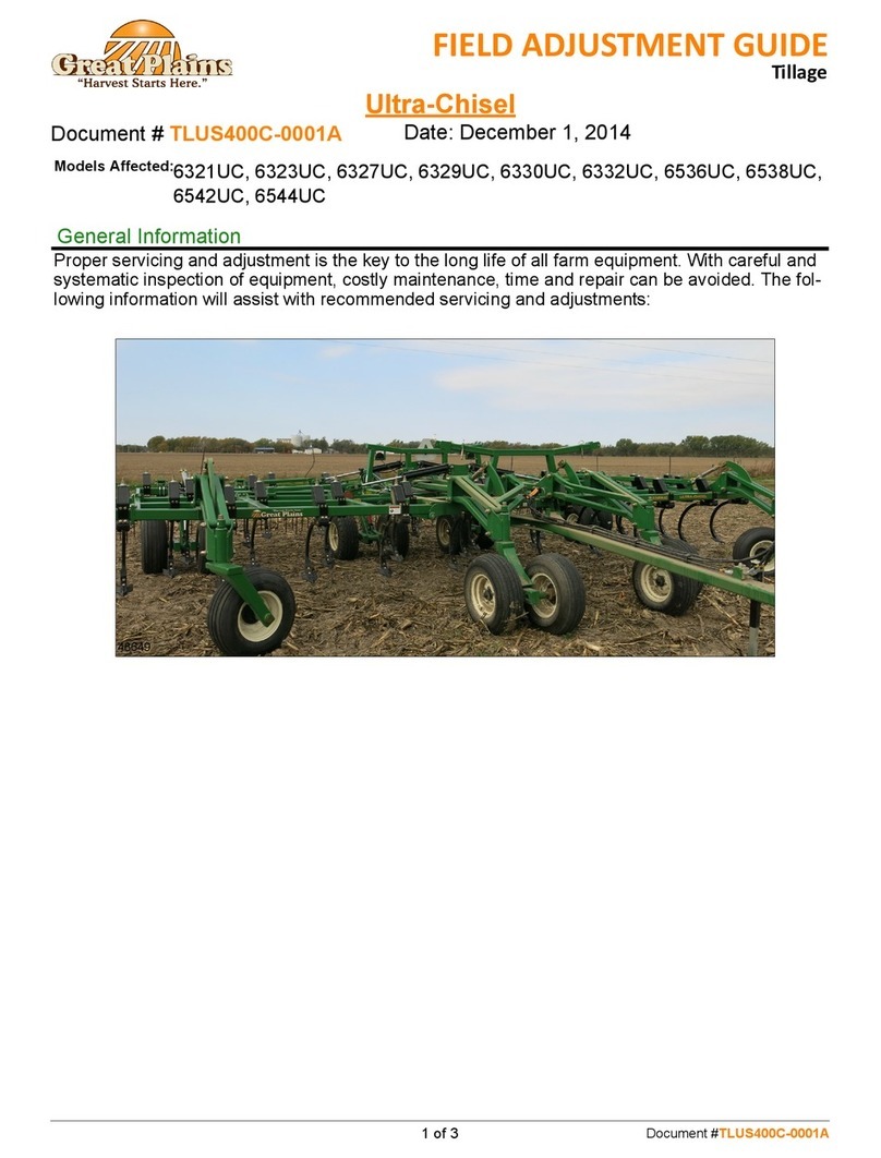
Turbo-Max
Proper servicing and adjustment is key to the long life of all farm equipment. With careful and systematic
inspection of equipment, costly maintenance, time and repair can be avoided. The following information
will assist with recommended servicing and adjustments:
49367
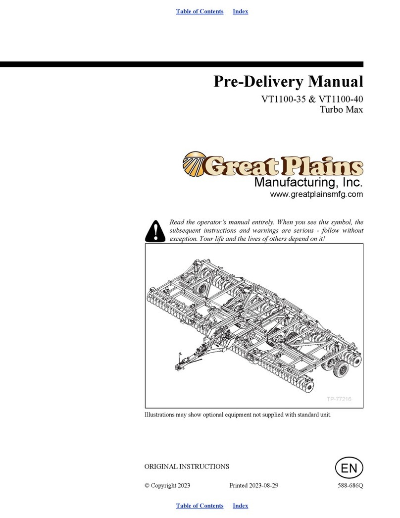
Models Affected:850TM, 1000TM, 1200TM, 1500TM, 2400TM, 3000TM, 3500TM, 4000TM, 4800TM
Date: March 26, 2018
General Information
Document #TLUS600C-0001B 2 of 7
49368
1
2
Tire Inflation Chart:
Ensure all tires are inflated to the proper operating
pressure per the table to the right. Note: Proper infla-
tion is important to ensure safe transport and level
operation of the Turbo-Max.
Tire Pressure
Position Size Pressure
Transport AW-708-19/45-17” 18-Ply BKT 65 PSI
Transport AW-708-19/45-17” 22-Ply BKT 78 PSI
Transport 480/45Rx17 AW711 BKT 73 PSI
Transport 480/45x17” Titan 58 PSI
Transport 380/55Rx16.5 Load F RI 73 PSI
Transport 340/60R16.5 73 PSI
Transport 440/55R18 Load 159A8/B Titan 78 PSI
Wings 12.5Lx15” 12-Ply 55 PSI
Wings 11Lx15SL 12-Ply 52 PSI
Gauge Wheel 9.5Lx15” 8-Ply 44 PSI
Hydraulic Hose Hookup
Color Function
Black Lift (2 Hoses)
Green Fold (2 Hoses)
Red Gang Adjustment (2 Hoses)
Yellow Hydraulic Reel Att. (2 Hoses) (Option)
Hydraulic Hose Hookup:
Great Plains hydraulic hoses have colored coded han-
dle grips to help hook up hoses to the tractor remotes.
Hoses with the same color use the same remote.
Front to Rear Leveling (Turnbuckle Option):
1) Completely unfold the machine while observing the
unit for any hydraulic leaks or loose fittings.
2) Once unfolded, raise the unit to re-phase the lift cir-
cuit. Hold the lift circuit open for 30 seconds to ensure
all air is purged from the hydraulic system.
3) Lower the machine so the front coulter gangs are 1-
2” off of a level surface.
4) Loosen the jam nut (1) and adjust the turnbuckle (2)
(shorten the turnbuckle to lower the front or extended
the turnbuckle to raise the front) until the front coulter
gangs are the same distance off the ground as the
rear coulter gangs.
5) Once level, re-tighten the jam nut (1).
Document #TLUS600C-0001B
3 of 7
49369
Front to Rear Leveling (Hydraulic Option):
1) Completely unfold the machine while observing the
unit for any hydraulic leaks or loose fittings.
2) Once unfolded, raise the unit to re-phase the lift cir-
cuit. Hold the lift circuit open for 30 seconds to ensure
all air is purged from the hydraulic system.
3) Lower the machine so the front coulter gangs are
1-2” off of a level surface.
4) Using the (yellow) hydraulic hoses, adjust the
hydraulic cylinder so that the front coulter gangs are
the same distance off the ground as the rear coulter
gangs.
4937049370
3
4
Level Bar Spring Adjustment:
1) To adjust the level bar spring assembly to the fac-
tory setting of 26 5/8”, loosen the jam nut (3).
2) Adjust the nut (4) until the 26 5/8” dimension is
reached between the backside of the spring guide
and front side of the level bar spring rod plate.
3) Once 26 5/8” is achieved, re-tighten the jam nut (3).
49373
56
Wing Adjustment Turnbuckle:
Note: Prior to leveling the wings, ensure that the
machine is level front to rear.
1) Lower the machine until the coulter gangs are 1-2”
off of the ground.
2) Loosen the jam nuts (5), and adjust the wing turn-
buckles (6) (shortening the turnbuckles raise the
wings and extending the turnbuckles lowers the
wings) to match the center frame.
3) Once the machine is leveled side to side, any fur-
ther adjustment in the field should be down with the
hydraulic down pressure.
Document #TLUS600C-0001B 4 of 7
49371
Gang Angle Adjustment:
Several conditions will dictate the gang angle setting
that will accomplish the desired result:
Example Of Suggested Settings:
1) Fall Operation: Cover residue and aggressively fill
in tracks.
Setting:
4-6 Degree Gang Angle
4-5” Working Depth
6-8 mph
2) Final Pass: Creating a level surface/planter-ready
seedbed.
Setting:
0 Degree Gang Angle
2” Working Depth
7-10 mph
49366
1/4” to 1/8”
77
Wing Fold Assist Proximity Sensors Adjustment
(If Installed):
Note: Wings must be folded up and the wing safety
lock pins installed when adjusting the proximity sen-
sors to prevent damage to the sensor and bracket.
1) Loosen the nuts (7) (one on the front and one on
the back side of the sensor bracket, adjust the proxim-
ity sensor to 1/8” to 1/4” from the front of the proximity
sensor to the rear of the wing tube).
2) Once adjusted, re-tighten the nuts (7) to secure the
proximity sensor in position.
Document #TLUS600C-0001B
5 of 7
48601
9
8
Hydraulic Down Pressure Adjustment: (1200TM,
1500TM, 1800TM, 2400TM, 3000TM)
Note: This setup procedure is for tractors with closed
center pressure compensated or pressure and flow
compensating hydraulic systems. Open center
hydraulics are NOT SUPPORTED.
1) With the machine unfolded, engage the fold/unfold
hydraulics for continuous flow (unfold position).
2) From the tractor cab, adjust the hydraulic flow so
the needle on the bypass gauge is in the green zone
1000-1500 psi (8). Note: The faster the flow of oil
through the system the greater the potential for oil
heating, premature wear or tractor damage.
3) At the valve, adjust the valve (9) to set the initial
down pressure. This is usually set at 300-400 psi (do
not exceed 800 psi).
During field operation, if the wings are running too
high, increase the pressure setting to help level the
machine. If the center of the machine is running too
high, decrease the pressure setting.
48602
10
11
Hydraulic Down Pressure Adjustment: (3500TM)
Note: This setup procedure is for tractors with closed
center pressure compensated or pressure and flow
compensating hydraulic systems. Open center
hydraulics are NOT SUPPORTED.
1) With the machine unfolded, engage the fold/unfold
hydraulics for continuous flow (unfold position).
2) From the tractor cab, adjust the hydraulic flow so
the needle on the bypass gauge is in the green zone
1000-1500 psi (10). Note: The faster the flow of oil
through the system the greater the potential for oil
heating, premature wear or tractor damage.
3) At the valve, adjust the valve (11) to set the initial
down pressure. This is usually set at 300-400 psi (do
not exceed 800 psi).
During field operation, if the wings are running too
high, increase the pressure setting to help level the
machine. If the center of the machine is running too
high, decrease the pressure setting.
Document #TLUS600C-0001B 6 of 7
48665
12
13
14
Hydraulic Down Pressure Adjustment: (4000TM,
4800TM)
Note: This setup procedure is for tractors with closed
center pressure compensated or pressure and flow
compensating hydraulic systems. Open center
hydraulics are NOT SUPPORTED.
1) Close the rear valve (12) by turning it clockwise
until it is completely closed. Then open the valve one
complete turn.
2) Set the tractor flow rate for the hydraulic fold/unfold
system to SLOW.
3) Engage the unfold hydraulic system (continuous
flow).
4) Adjust the front valves (13)(14) to obtain 1200 psi
each.
5) Adjust the rear valve (12) to 1100 psi. Once
achieved, lock the valve using the locking disc.
6) Adjust the front valves (13)(14) to the desired down
pressure. It is recommended to adjust valve (13)
between 300-800 psi for the inner wings and adjust
valve (14) between 200-500 psi for the outer wings.
During field operation, if the wings are running too
high, increase the pressure setting on valves (13)(14)
to help level the machine. If the center of the machine
is running too high, decrease the pressure setting on
valves (13)(14).
49374
15
Hydraulic Single Point Depth Stop Adjustment:
The hydraulic dept stop will ensure a consistent depth
every time the implement is lowered.
1) Prior to setting the single point depth stop, ensure
that the machine is completely level front to back and
side to side.
2) Lower the implement to the desired working depth
and pull forward. Once satisfied with the working
depth, adjust the depth stop handle to make contact
with the depth stop valve. Note: If a change of depth is
desired, 1 full turn of the depth stop handle either in or
out will change the depth of the machine approxi-
mately 1/4” up or down.
Document #TLUS600C-0001B
7 of 7
49375
16
17
Gauge Wheel Adjustment:
Note: The gauge wheels should be set in the field
position to be 1/2” to 1 1/2” off the ground.
1) Loosen the set screws (16) on each gauge wheel.
2) Turn the jack handle (17) to adjust the spindle
receiver. Adjusting the jack handle counterclockwise
will run the wheel closer to the ground while turning
the jack handle clockwise will cause the wheel to run
further away from the ground.
3) After adjusting the gauge wheel to the desired posi-
tion, re-tighten the set screws (16).
49376
18
19
Rolling Reel Spring Adjustment:
The reel down pressure may be adjusted by removing
the pin (18) and then either pushing the handle (19)
forward to increase the spring pressure or by pulling
the handle backwards to decrease the spring pres-
sure. When the desired amount of spring pressure is
achieved, re-insert the pin. Note: It is recommended
to run little or no down pressure in wet conditions.
49372
Hydraulic Rolling Reel Adjustment: (Option)
Reel down pressure can be adjusted on the move
depending on the desired results.
Using the gauge on the back of the machine:
0 = No pressure/transport position/wet conditions
1-5 = Ideal operating range
6 = Most pressure/extremely hard soil
Note: Running the rolling reel at 6 can raise the rear of
the machine out of the ground and can cause the
machine to be unlevel.

This manual suits for next models

8

Other GREAT PLAINS Farm Equipment manuals
GREAT PLAINS NTA607HD User manual

GREAT PLAINS

GREAT PLAINS NTA607HD User manual

GREAT PLAINS 3P605NT User manual

GREAT PLAINS

GREAT PLAINS 3P605NT User manual

GREAT PLAINS Nutri-Pro NP30A User manual

GREAT PLAINS

GREAT PLAINS Nutri-Pro NP30A User manual

GREAT PLAINS Turbo Max 1800TM User manual

GREAT PLAINS

GREAT PLAINS Turbo Max 1800TM User manual

GREAT PLAINS 3S-5000 Series User manual

GREAT PLAINS

GREAT PLAINS 3S-5000 Series User manual

GREAT PLAINS Yield-Pro 3P4025AH Guide

GREAT PLAINS

GREAT PLAINS Yield-Pro 3P4025AH Guide

GREAT PLAINS 1510HDP User manual

GREAT PLAINS

GREAT PLAINS 1510HDP User manual

GREAT PLAINS NTA3010 User manual

GREAT PLAINS

GREAT PLAINS NTA3010 User manual

GREAT PLAINS RC2515 User manual

GREAT PLAINS

GREAT PLAINS RC2515 User manual

GREAT PLAINS Yield-Pro Air-Pro YP2425A User manual

GREAT PLAINS

GREAT PLAINS Yield-Pro Air-Pro YP2425A User manual

GREAT PLAINS Qualidisc HS2200-13 User manual

GREAT PLAINS

GREAT PLAINS Qualidisc HS2200-13 User manual

GREAT PLAINS SPARTAN II User manual

GREAT PLAINS

GREAT PLAINS SPARTAN II User manual

GREAT PLAINS HT1100-35 User manual

GREAT PLAINS

GREAT PLAINS HT1100-35 User manual

GREAT PLAINS BD7600 User manual

GREAT PLAINS

GREAT PLAINS BD7600 User manual

GREAT PLAINS Nutri-Pro NP1330AA Guide

GREAT PLAINS

GREAT PLAINS Nutri-Pro NP1330AA Guide

GREAT PLAINS 8323 User manual

GREAT PLAINS

GREAT PLAINS 8323 User manual

GREAT PLAINS VT1510 User manual

GREAT PLAINS

GREAT PLAINS VT1510 User manual

GREAT PLAINS 7000 Series User manual

GREAT PLAINS

GREAT PLAINS 7000 Series User manual

GREAT PLAINS 3N-3010 User manual

GREAT PLAINS

GREAT PLAINS 3N-3010 User manual
GREAT PLAINS BD7600 User manual

GREAT PLAINS

GREAT PLAINS BD7600 User manual
GREAT PLAINS Short Disk SD2600 Guide

GREAT PLAINS

GREAT PLAINS Short Disk SD2600 Guide

GREAT PLAINS Yield-Pro Air-Pro YP625PD User manual

GREAT PLAINS

GREAT PLAINS Yield-Pro Air-Pro YP625PD User manual

GREAT PLAINS BD7600 User manual

GREAT PLAINS

GREAT PLAINS BD7600 User manual

GREAT PLAINS Turbo Max 3500TM User manual

GREAT PLAINS

GREAT PLAINS Turbo Max 3500TM User manual

Popular Farm Equipment manuals by other brands

BEEHIVE M59701 Assembly instructions

BEEHIVE

BEEHIVE M59701 Assembly instructions

Terrateck RJP 80M instruction manual

Terrateck

Terrateck RJP 80M instruction manual

Agrident AWR300 user guide

Agrident

Agrident AWR300 user guide

Vaderstad Rapid RDA 400S instructions

Vaderstad

Vaderstad Rapid RDA 400S instructions

Finn BARK BLOWER BB-1208 Parts and Operator's Manual

Finn

Finn BARK BLOWER BB-1208 Parts and Operator's Manual

Land Pride CB0550 Operator's manual

Land Pride

Land Pride CB0550 Operator's manual

MANN LAKE HH-200 quick guide

MANN LAKE

MANN LAKE HH-200 quick guide

Raven RS1 Guidance and Steering Installation Manual

Raven

Raven RS1 Guidance and Steering Installation Manual

USC LPX2000 Operator's manual

USC

USC LPX2000 Operator's manual

GSi TopDry Batchflow 30 FT Construction manual

GSi

GSi TopDry Batchflow 30 FT Construction manual

Gallagher 033515 instruction manual

Gallagher

Gallagher 033515 instruction manual

Harvest TEC 436 owner's manual

Harvest TEC

Harvest TEC 436 owner's manual

Sime GEMINI INSTALLATION, USE, MAINTENANCE AND SPARE PARTS MANUAL

Sime

Sime GEMINI INSTALLATION, USE, MAINTENANCE AND SPARE PARTS MANUAL

KW Cages Pro Pig 3952 Assembly instructions

KW Cages

KW Cages Pro Pig 3952 Assembly instructions

APV AS 300 M1 operating manual

APV

APV AS 300 M1 operating manual

dosatron D 20 S owner's manual

dosatron

dosatron D 20 S owner's manual

Molon BCS operating instructions

Molon

Molon BCS operating instructions

Cima BLITZ Maintenance Instruction

Cima

Cima BLITZ Maintenance Instruction

manuals.online logo
manuals.online logoBrands
  • About & Mission
  • Contact us
  • Privacy Policy
  • Terms and Conditions

Copyright 2025 Manuals.Online. All Rights Reserved.