Grillo G52 User guide

02156
G52
USO E MANUTENZIONE
USE AND MAINTENANCE
- EDIZIONE 2007
GEBRAUCHS- UND WARTUNGSANLEITUNG
EMPLOI ET ENTRETIEN
USO Y MANTENIMIENTO

GB
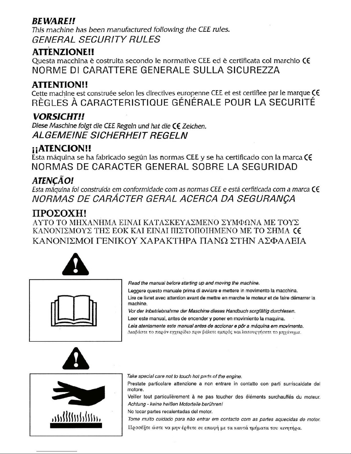
Safety rules ...................................................................................................................................................... p. 1
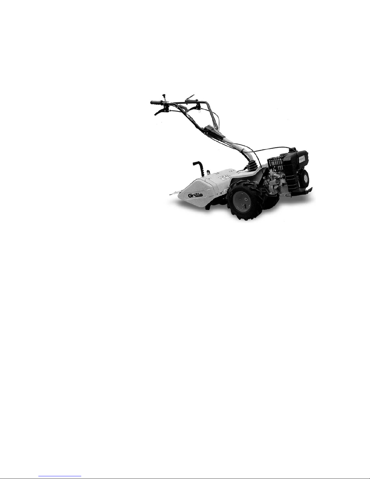
Rotovator.......................................................................................................................................................... p. 6
Identification and after-sales service................................................................................................................ p. 6
Technical data .................................................................................................................................................. p. 7
Instructions for use........................................................................................................................................... p. 7
Putting the machine into service ...................................................................................................................... p. 7
Maintenance and lubrication ............................................................................................................................ p. 8
Implements....................................................................................................................................................... p. 8
Description of the controls................................................................................................................................ p. 31
Noise level – vibration level.............................................................................................................................. p. 36
I
Norme antinfortunistiche .................................................................................................................................. p. 1
Motocoltivatore................................................................................................................................................. p. 11
Identificazione e assistenza ............................................................................................................................. p. 11
Caratteristiche tecniche.................................................................................................................................... p. 12
Istruzioni d’uso ................................................................................................................................................. p. 12
Messa in opera della macchina........................................................................................................................ p. 12
Manutenzione e lubrificazione.......................................................................................................................... p. 13
Attrezzi ............................................................................................................................................................. p. 14
Descrizione dei comandi .................................................................................................................................. p. 31
Rumorosità – vibrazioni.................................................................................................................................... p. 36
F
Règles de sécurité générale ............................................................................................................................ p. 1
Motoculteur ...................................................................................................................................................... p. 16
Identification et assistance............................................................................................................................... p. 16
Caractéristiques techniques............................................................................................................................. p. 17
Mode d’emploi.................................................................................................................................................. p. 17
Mise en service de la machine......................................................................................................................... p. 17
Entretien et lubrification.................................................................................................................................... p. 18
Accéssoires...................................................................................................................................................... p. 18
Description des commandes............................................................................................................................ p. 31
Bruit – vibrations .............................................................................................................................................. p. 36
D
Sicherheitsvorschriften..................................................................................................................................... p. 1
Einachsschlepper............................................................................................................................................. p. 21
Identifikation und Kundendienst....................................................................................................................... p. 21
Technische Daten............................................................................................................................................. p. 22
Bedienungsanleitung........................................................................................................................................ p. 22
Inbetriebnahme der Maschine.......................................................................................................................... p. 22
Wartung und Schmierung................................................................................................................................. p. 23
Anbaugeräte..................................................................................................................................................... p. 23
Beschreibung der Bedienungseinrichtungen ................................................................................................... p. 31
Geräuschemission – Vibrationen ..................................................................................................................... p. 36
E
Normas de seguridad....................................................................................................................................... p. 1
Motocultor ........................................................................................................................................................ p. 26
Identificación y asistencia ................................................................................................................................ p. 26
Características técnicas ................................................................................................................................... p. 27
Instrucciones de uso ........................................................................................................................................ p. 27
Puesta en marcha de la máquina .................................................................................................................... p. 27
Manutencion y lubricación................................................................................................................................ p. 28
Accesorios........................................................................................................................................................ p. 28
Descripción mandos......................................................................................................................................... p. 31
Niveles del ruido - vibración ............................................................................................................................. p. 36

1

2

3

4
Grillo G52
000000
57 kg.
2.9/3.7/3600
tipo
serie
massa c.a.
anno
KW/giri minuto
S.p.A.
CESENA - ITALY
Cod. 03207
2003

Warning! Turning gears, keep your hands
and feet away. Do not clean the attachment
when the engine is running.
Attenzione! Organo in rotazione, tenere
lontano piedi e mani. Non pulire l’attrezzo
col motore in moto.
Attention! Organe en rotation, ne pas
approcher mains et pieds. Ne pas nettoyer
l’outil quand le moteur est en marche.
Achtung! Rotierende klinge, Hände und Füße
fernhalten. Niemals bei laufendem Motor
reinigen.
¡Atención! Órgano en rotación, mantener
lejos los pies y las manos. No limpiar la
herramienta con el motor en marcha.
Atenção! Órgão em rotação. Mantenha as
mãos e os pés afastados. Não limpe o
equipamento com o motor em movimento.
5

6
ROTOVATOR
Dear Customer,
Thank you for choosing our rotovator; we are sure that your new machine’s performance will meet your
requirements in full.
To ensure optimum service and maintenance of its qualities over time, read this manual carefully and follow its
instructions. This will give you the best results and protect your investment.
Please keep this manual, which must always accompany the machine.
CAUTION! Before starting the engine, read this carefully.
The following warnings are very important in ensuring safety!
SAFETY REGULATIONS
Caution is your main weapon in preventing accidents!
We urge you to read the following regulations for use of the machine carefully before starting work.
Improper use of the machine and its equipment may cause damage; to reduce this risk, read the following
precautions carefully.
1) Read the whole of this manual before starting the machine or putting it in motion.
2) Pay special attention to the safety warnings and labels.
3) Rotation of the tiller is extremely dangerous; never insert hands or feet under the tiller!
4) Before other people are allowed to use the machine they must first be informed about the safety regulations
and how to use the vehicle.
5) Before starting the engine, make sure that there is no-one nearby, particularly children.
6) Never use the machine when tired and do not drink alcohol.
7) Check the ground before tilling for stones, sticks or foreign bodies which might damage the machine or be flung
dangerously to some distance during operation.
8) Before starting work, put on suitable working clothes, gloves, heavy footwear and goggles.
9) Never use the rotovator on steep slopes; it might tip over.
10) Never allow the machine to be used by anyone under 16 years of age.
11) Never reverse with the engine at high throttle.
12) It is dangerous to operate the levers sharply with the engine at maximum rpm.
13) Never keep the engine running indoors; you may inhale poisonous gases.
14) Always switch off the engine before filling up with fuel, keep away from sparks or flames and do not smoke!
15) Avoid fuel spills and after filling the tank clean all spills before starting the engine.
16) Never tamper with or disable the safety devices.
17) Never make any adjustments or do any cleaning with the engine running.
18) Never have anyone check the machine while you are driving with the engine running.
19) The user is always responsible for injury or damage to third parties.
20) Any improper uses causes the machine to become null and void and the constructor will decline all liability.
21) Misshapen or damaged hoes must always be replaced and never repaired.
22) Always use original Grillo spare parts.
23) Before starting any work with the machine, check that all the accident prevention systems with which it is
equipped are in perfect working order. They must never be disabled or tampered with.
24) Before starting work, check that the nuts and bolts securing the tiller and hoes are perfectly tight.
25) All protective fittings (hoods, mudguards, etc.) must be kept in place during operation.
26) Never clean the tiller with the engine running.
27) Never use the machine barefoot.
IDENTIFICATION AND AFTER-SALES SERVICE
The vehicle’s serial number is punched on the nameplate on the left-hand longitudinal member of the chassis and
on the gearbox nameplate.
Always state the serial number when ordering spare parts.

7
TECHNICAL DATA
Engine: 4 stroke petrol engine TECUMSEH GEOTECH 50 - LOMBARDINI LGA 226 - BRIGGS & STRATTON INTEK
5.5 HP – HONDA GC 160
Gearbox: 2 speed gears in oil bath (one forward and one reverse).
Power-take-off: at 644 rpm as walking tractor in anti-clockwise direction of rotation; at 965 rpm as motor mower in
clockwise direction of rotation.
Safety device: engaging the reverse gear the rotary tiller disconnects automatically.
Handlebar: adjustable in height and sideway and revolving.
Rotary tiller: standard: 500 mm (adjustable 500 - 370 mm).
Attachments: rotary tiller, cutter bar, snow thrower, rotary cutter, spraying pump, cage steel wheels, wheel-weights,
wheel extensions, barrow, grass cutter cm. 50, combined furrower, trailer, tilting front dozer blade cm. 80.
Weight: machine in working order with rotary tiller: 66 kg.
Speeds with 13.50-6 tires:
As walking tractor: forward speed 1.4 km/h - reverse speed 2.2 km/h.
As motor mower: forward speed 2.2 km/h - reverse speed 1.4 km/h.
INSTRUCTIONS FOR USE
PUTTING THE MACHINE INTO SERVICE
1) Fill engine oil to level (please refer to relevant engine handbook).
2) Check the BLASIA 220 gearbox oil (or international equivalent ISO-L-CKD, DIN 51502 PGLP) or ROTRA MP 80W90
(API GL 5).
Do not turn on the engine without first checking:
– all screws and nuts are well tightened;
– the reversing device lever on gearbox housing is on the right position;
MOTOCOLTIVATORE (walking tractor) A
MOTOFALCIATRICE (motor mower) B (fig. 1)
– the attachments engaging lever (fig. 2 no. 3) is in idle position (in the fig. no. 2 the attachment is engaged) the
advancement control lever (fig. 2 no. 1) are in idle position (fig. 3);
– air filter is clean (fig. 4 - fig. 6);
– to fill in the tank use a funnel with a very fine filter;
– the attachments are properly fixed to the machine (fig. 5-6);
– adjust handlebar height (fig. 2 no. 4).
HOW TO START THE ENGINE
Open the fuel tap (fig. 7 no. 2), push the gas control lever halfway (fig. 2 no. 5). Press the dead-man handle (fig. 2 no. 6).
If the engine is cold operate the starter device on the carburettor (fig. 7 no. 1) choke position (please refer to relevant engine
handbook); grip the starting handle (fig. 8) and jerk strongly. When the engine has started it is necessary to set the starting
device back to the «RUN» position; then the gas lever slowly to the minimum.
HOW TO START THE MACHINE
Keep the engine at a low rating; engage the implement by leaving the lever no. 3 (fig. 2); accelerate properly and leave
the wheel engaging lever (fig. 2 no. 1): the machine will start moving. Pulling the lever no. 1 (fig. 2) the machine stops.
Pulling the lever no. 2 (fig. 2) the machine goes backward. To lock the levers, hook the lever clip (fig. 3). Operating the
lever (fig. 9) it is possible to adjust the handlebar laterally «one right-hand position - one left-hand position» either as
walking tractor or as motor mower.
END OF WORK
When work is ended, to stop the engine; press the button (fig. 2 no. 8) and close the fuel tap (please refer to relevant engine handbook).
POSSIBLE INCONVENIENCES AND SOLUTIONS
The following inconveniences can be fixed up by the operator himself. If the engine does not start, check in the following order that:
– the fuel tank is at least half full;
– the fuel tap is open;
– the starting device is operating (when the engine is cold) fig. 7 CHOKE;
– fuel gets to the carburettor;
– the breather hole on the tank plug is not obstructed;
– the air filter is clean (fig. 4 - fig. 6);
– current gets to the spark plug (fig. 10); (please refer to relevant engine handbook). If current does not arrive, after
checking the electric cables have no defects and the plug is clean, change the plug taking care to buy another one with
the same heat rating. If this attempt also should turn out to be useless, the failure must be searched in the magneto
flywheel; at this point it is advisable to go to the nearest service-centre.

8
MAINTENANCE AND LUBRICATION
LUBRICATION: do the following operations with machine in horizontal position.
N.B.: the oil change must be effected with warmed up machine in order to help the total oil drainage.
ENGINE OIL: Follow the instructions on the «Engine operator’s manual» carefully. It is however necessary to
check the oil level every 4 hours taking the plug off (fig. 11 no. 1) and checking that oil reaches the hole border.
Change lubricant the first time after 20 hours. The change it every 50 hours (please refer to relevant engine
handbook).
Unscrew the plug (fig. 11 no. 2).
GEARBOX OIL: check oil level every 50 working hours unscrewing the screw (fig. 1 no. 1). If necessary add some
BLASIA 220 (quantity: 750 gr.) lubricant.
Change oil once per year.
To drain the oil unscrew the plug (fig. 12 no. 1).
MAINTENANCE: after the first working hours, it might be necessary to check and adjust the wheel releasing cable
and the reversing device cable acting on the adjuster situated on the handle (fig. 3). The quick coupling must be
always clean and greased.
To remove the fairing pull upward. The same for the cutter bar conveyor.
Spare parts we recommend to have in stock:
– 1 accelerator cable
– 1 wheel engaging cable
– 1 gas throttle lever
– 5 blade fingers
– 1 complete blade
– 10 cutter bar nails
– 2 cutter bar fingers
– 10 cutter bar finger nails
– 1 right tyne
– 1 left tyne.
HOW TO ORDER SPARE PARTS: address to your area agent or local dealer in your Country. Always give the
machine serial number and part number:
GRILLO S.p.A.
Via Cervese 1701 - 47023 CESENA (FC) ITALY
Tel. 0039 - 0547 - 633.111 / Fax 0039 - 0547 - 632.011
END OF SEASON MAINTENANCE
Clean the machine carefully: the air filter, the cutter bar and the rotary tiller.
Change engine and gearbox oil.
Put two wooden boards under the wheels.
I M P L E M E N T S
ROTARY TILLER
The rotary tiller is used to break the superficial layer of the ground so that its permeability is increased and, at the
same time, to rid of weeds (fig. 13).
Tilling depth can be adjusted by lifting or lowering the central knife situated under the rotary unit. To increase depth
it is necessary to lift the knife. It is advisable to start working with the knife in the lowest position and lift it when a
deeper tillage is requested. For a better tillage it is advisable to use the wheel extensions either with cage wheels
or pneumatic wheels.
Important
To protect the machine transmission, the rotary tiller is fitted with two safety screws, which fix the tines in case a
stone or any other foreign object suddenly block the tiller rotation. Should this happen, you have to stop immediately
the engine and to replace the screws, which fix the tines group to the tines shaft. Please use steel screws 1.29.

9
N.B.: on hard soils the machine may jump forward. If so, lower the central knife to the maximum keeping
the slide horizontal (fig. 14). Check the tynes are properly placed on (fig. 15). Check oil level every 20 hours
(fig. 15 no. 2) adding 85W/90 lubricant, if necessary.
To narrow the rotary tiller to 37 cm, you need the part number 929512.
CUTTER BAR
The cutter bar attachable to this machine can be with central control (fig. 16).
Its strong construction and high performances make it the ideal means to mow small pieces of land, parks and
gardens.
The cutter bar must be fixed to the attachments coupling in place of the rotary tiller just by means of the locking
rod (fig. 5): let the eccentric lever be free (fig. 5) in order to allow it to swing.
It is possible to equip the central cutter bar with the slides in order to adjust cutting height.
The handlebar must be turned 180°on the engine side operating the handlebar adjustment lever (fig. 9).
Maintenance
– Check the blade holders are always well adjusted (fig. 18) but not too tight because the engine might stop once
the cutter bar is engaged and the cutter bar could be damaged by overheating. The blade must turn by operating
the hand-wheel.
– Check the blade is well sharpened.
– Sharpen the cutting edges on the upper side (fig. 19).
– Check the blade movement is always properly tightened and lubricated while working (fig. 20).
– When work is finished the cutter bar must be washed and lubricated.
SAFETY DEVICE FOR G52 CUTTER BAR FIG. 17
On the G52 cutter bar a safety device has been assembled in order to protect the cutter bar itself if a foreign body
suddenly stops the blade. If, after a certain period of work, and after several sudden stops on the blade, the cutter
bar doesn’t work as well as before, it is necessary to add one or two 0,5 mm washers see the picture in order to
adjust the spring pressure on the couplings.
Actions:
1) Disconnect the cutter bar from the machine using the attachment blockage lever.
2) Unscrew the screw nr. 1.
3) Extract the washer nr. 2.
4) Add one or more shins 0,5 mm.
5) Reassemble the washer nr. 2, the screw and the cutter bar onto the machine.
WHEEL EXTENSIONS
They are used to widen the track, consequently increasing the machine stability on crosswise slopes. They must
be fixed between the wheels and the wheel shaft. The track is thus widened by 5 cm on each side.
ROTARY CUTTER
This implement (fig. 21), specially studied for parks and gardens maintenance, has a cutting width of 50 cm. Its
high power and the driving wheels allow to operate in all conditions without tiring the operator. The lawn mower
is attachable to the implement frame of the walking tractor and it is used with the handlebar turned over the engine.
The transmission of the movement to the blade is obtained by a bevel gear pair. The grass shredder is equipped
with a releasing device on the coupling, in order the machine is not damaged by its inertia when the reverse gear
is operated.
Cutting height can be regulated adjusting the position of the little front wheel, thus changing the lateral rams position
(fig. 22).
Maintenance
Keep the rotary cutter blade clean and well sharpened: cut will be better and the engine will not strain. Always
tighten the fixing bolt well when fastening or removing the blade. Check gearbox oil level every 50 hours removing
the plug situated on top of the box and make sure oil level reaches at least 50 mm from the hole. If necessary add
85W/90 lubricant. Replace oil once per year.

10
CAUTION: the blade rotation is very dangerous. Please keep hands and foot far from the blade. Do not clean the
implement when the engine is running.
SNOW THROWER
This implement, specially designed for this walking tractor, is very helpful to clear of snow yards, driveways, etc.
(fig. 23).
It consists of a turbine rotary unit enclosed in a special casing opened on the front side which, turning at a high
speed, collects snow and throws it through a pipe whose inclination can be adjusted. Snow may be thrown 8-10
mt far in any desired position.
The snow thrower is attachable to the flange for attachments and it is fixed by the specific lever.
The handle must be turned 180°on the engine side.
The throwing pipe adjustment rod must be fixed under the handlebar adjusting lever (fig. 24).
The snow thrower is 50 cm wide and can clear off snow up to 30 cm high. In case snow is very wet it is convenient
to keep the throwing pipe forward to avoid obstructions at the outlet. The two side skids must be adjusted so that
they just skim the ground if this is level (asphalted roads), or to keep the snow thrower high if the ground is uneven.
Maintenance
When work is finished it is convenient to remove the snow thrower in order to prevent its blocking the turbine by
freezing.
Check oil level inside the central box where the bevel torque is placed and add 85W/90 lubricant (high pressure),
if necessary.
WHEEL WEIGHTS
The wheel weights must be fixed to the rims of the cage or garden wheels by four nuts. They are used to increase
the machine weight and therefore its adhesion; they are advised when working with the furrower and even with the
rotary tiller, when special performances are required. They cannot be used with the pneumatic wheels.
They weigh 7 kg each (fig. 25).
CAGE STEEL WHEELS
These wheels are particularly useful to work with the rotary tiller on very hard or grassy soils. In fact the cross bars
placed around the wheels, penetrate into the ground assuring a perfect berth of the machine preventing the wheels
from skidding (fig. 26). The cage wheels are also advised when pneumatic wheels, might skid or sink in moist or
soft grounds, when they have just been tilled. The use of cage wheels is recommended if it is restricted to such
cases. Otherwise, if a particular adhesion is not required, it is usually advised the use of pneumatic wheels that give
the machine a more regular traction and form an elastic buffer between the machine and the ground.
COMBINED FURROWER
Like the adjustable furrower, this implement is used for preparing furrows for sowing and irrigation, but it is mounted
above the rotary tiller instead of the tiller cover, and the two implements work together. The traction provided by
the wheels is increased by the propulsive action of the rotary tiller (working on the ground), for easier forward
movement even on particularly hard soils.
The furrower height can be adjusted using the rear support rod which has several holes. The furrow depth can also
be varied by changing the mounting position. The width can be adjusted by changing the position of the two back
wings (fig. 27).
TRAILER
The trailer is mounted on the tool flanging. It is equipped with a dumper and reversible wheels to make steering
easier (figure 28).
TILTING FRONT DOZER BLADE - 80 cm
This highly resistant device is ideal for removing snow and levelling mounds of soil or gravel. May be tilted to the
right and left (figure 29).

11
MOTOCOLTIVATORE
Gentile Cliente,
nel ringraziarLa per la fiducia e la preferenza accordata al nostro motocoltivatore, confidiamo che l'uso di questa
sua nuova macchina risponda pienamente alle sue esigenze.
Per l'impiego ottimale e per la sua manutenzione nel tempo, la preghiamo di leggere attentamente e seguire
scrupolosamente le indicazioni di questo libretto; ciò le consentirà di ottenere i massimi risultati e salvaguardare
la sua spesa.
La preghiamo di conservare questo libretto, che dovrà sempre accompagnare la macchina.
IDENTIFICAZIONE E ASSISTENZA
IDENTIFICAZIONE
La macchina è fornita di una targhetta posta sul telaio con il numero di matricola.
Questo numero è indispensabile per ogni richiesta di intervento tecnico e per l'ordinazione dei ricambi.
ATTENZIONE! Prima di avviare il motore leggere attentamente.
Le seguenti avvertenze sono importanti per l'incolumità!
NORME ANTINFORTUNISTICHE
La prudenza è l'arma principale nella prevenzione degli incidenti!
La preghiamo vivamente di leggere con attenzione le seguenti avvertenze, prima ancora di iniziare il lavoro.
L'uso improprio del motocoltivatore e il suo equipaggiamento può risultare dannoso; per ridurre queste possibilità
osservare le precauzioni necessarie di seguito riportate:
1) Leggere questo manuale interamente, prima di accendere e mettere in movimento il motocoltivatore.
2) Dare particolare attenzione alle ammonizioni e alle etichette di sicurezza attorno alla macchina.
3) La rotazione della fresa è altamente pericolosa, non mettere mai le mani o i piedi sotto alla fresa.
4) Prima di fare lavorare col motocoltivatore altre persone bisogna metterle al corrente delle norme di sicurezza
e di come si usa la macchina.
5) Prima di accendere il motocoltivatore verificare che non ci siano persone intorno; specialmente bambini.
6) Non usare il motocoltivatore quando si è affaticati e non bere alcoolici.
7) Controllare il terreno prima di procedere alla fresatura, che non vi siano sassi, bastoni o corpi estranei, che
potrebbero danneggiare la macchina o essere scagliati lontano, e quindi molto pericolosi.
8) Prima di iniziare il lavoro, indossare indumenti appropriati da lavoro, guanti, scarponi, occhiali.
9) Non usare il motocoltivatore su forti pendenze, si potrebbe ribaltare.
10) Non fare lavorare ragazzi troppo giovani; è vietato l'uso ai minori di 16 anni.
11) Non fare retromarcia col motore accelerato.
12) È pericoloso azionare le leve bruscamente, col motore a massimo regime.
13) Per evitare il pericolo di esalazioni velenose, non adoperare il motore acceso in un locale chiuso.
14) Spegnere sempre il motore prima di fare rifornimento di combustibile, stare lontano da scintille o fiamme, non
fumare!
15) Evitare fuoriuscite di combustibile e dopo aver riempito il serbatoio pulire ogni fuoriuscita prima di avviare il
motore.
16) Non manomettere o disattivare i dispositivi di sicurezza.
17) Non fare nessun tipo di regolazione o pulizia col motore in moto.
18) Non fare controllare la macchina da nessuno mentre siete alla guida col motore in moto.
19) L'utilizzatore è sempre responsabile dei danni arrecati a terzi.
20) Ogni utilizzo improprio comporta il decadimento della garanzia ed il declino di ogni responsabilità del
costruttore.
21) Le zappe deformate o danneggiate devono essere sempre sostituite, mai riparate.
22) Usare sempre ricambi originali Grillo.
23)
Prima di cominciare qualsiasi lavoro con la macchina, verificare che tutti i sistemi antinfortunistici, di cui essa
è dotata, siano perfettamente funzionanti. È severamente vietato escluderli o manometterli.
24) Prima di iniziare il lavoro, controllare che le viti e i dadi di bloccaggio della fresa e delle zappette siano
perfettamente serrati.
25) L'attrezzatura protettiva (cofani, parafanghi, ecc.), va assolutamente mantenuta durante i lavori di zappatura.
26) Non pulire la fresa con il motore acceso.
27) Non utilizzare la macchina a piedi nudi.

12
CARATTERISTICHE TECNICHE
Motore: 4 tempi a benzina TECUMSEH GEOTECH 50 - LOMBARDINI LGA 226 - BRIGGS & STRATTON INTEK
5,5 HP - HONDA GC 160.
Cambio: Con ingranaggi in bagno d'olio a 2 marce (una in avanti ed una in retromarcia).
Presediforza: A 644 giri in versione motocoltivatore e senso di rotazione antiorario; a 965 giri in versione falciatrice
e senso di rotazione orario.
Dispositivo di sicurezza: Innestando la retromarcia la fresa si disinnesta automaticamente.
Stegole: Regolabili sia in altezza che lateralmente reversibili.
Fresa: STANDARD mm. 500 registrabile 500 - 370 mm.
Applicazioni: Fresa, barra falciante, spazzaneve, pompa irrorazione, ruote a gabbia, zavorre, allargamenti ruote,
carrello contenitore, trinciaerba, ruspa frontale orientabile, assolcatore combinato.
Peso: Con fresa Kg. 66.
Velocità con ruote 13.50-6:
In versione motocoltivatore - in avanti Km/h. 1.4 - in retromarcia Km/h. 2.2.
In versione falciatrice - in avanti Km/h. 2.2 - in retromarcia Km/h. 1.4.
ISTRUZIONI D'USO
MESSA IN OPERA DELLA MACCHINA
1) Inserire l'olio motore (vedi apposito libretto).
2) Controllare l'olio cambio BLASIA 220 (ISO-L-CKD, DIN 51502 PGLP) o ROTRA MP 80W90 (API GL 5).
Prima di avviare il motore controllare sempre:
– Che tutte le viti e i dadi siano ben serrati.
–
Che la levetta invertitore sul carter cambio sia nella posizione giusta «Motocoltivatore (A) o Motofalciatrice (B)» Fig. 1.
– Che la leva innesto attrezzi (Fig. 2 n°3) sia in posizione di folle (nella figura l'attrezzo è innestato). La leva
comando avanzamento (Fig. 2 n°1) sia in posizione di folle (Fig. 3).
– Che il filtro aria sia ben pulito (Fig. 4 - Fig. 6).
– Riempire il serbatoio di carburante servendosi di un imbuto munito di filtro molto fine.
– Che gli attrezzi siano ben fissati alla macchina (Fig. 5).
– Posizionare all'altezza giusta la stegola (Fig. 2 n°4).
AVVIAMENTO DEL MOTORE
Aprire il rubinetto del carburante (Fig. 7 n°2), spingere fino a metà la levetta comando gas (Fig. 2 n°5), agganciare
il motor stop (Fig. 2 n°6) se il motore è freddo, azionare il dispositivo di starter sul carburatore (Fig. 7 n°1) posizione
choke (vedi libretto motore); afferrare la maniglia di avviamento (Fig. 8) e dare uno strappo energico.
Avviato il motore riportare ai primi scoppi lo starter in posizione RUN, poi lentamente la levetta acceleratore al minimo.
AVVIAMENTO DELLA MACCHINA
Tenere il motore a basso regime, innestare l'attrezzo lasciando la leva n. 3 (Fig. 2), accelerare opportunamente
e lasciare la leva innesto ruote (Fig. 2 n°1), la macchina si metterà in movimento.
Tirando la leva n. 1 (Fig. 2) la macchina si arresta.
Tirando la leva n. 2 (Fig. 2) la macchina retrocede.
Per bloccare le leve agganciare il fermaglietto (Fig. 3). Azionando la levetta (Fig. 9) si può spostare lateralmente
la stegola «1 posizione a destra n°1 posizione a sinistra» sia in versione motocoltivatore che in versione falciatrice.
FINE LAVORO
Terminato il lavoro, per arrestare il motore, spingere il pulsante (Fig. 2 n°8) chiudere il rubinetto del carburante
(vedi libretto motore).
POSSIBILI INCONVENIENTI E LORO RIMEDI:
Diamo qui di seguito un elenco di piccoli inconvenienti che possono essere rimediati direttamente dal cliente.
1) Il motore non parte:
Eseguire nell'ordine i seguenti controlli:
– Che il serbatoio della benzina sia pieno almeno per metà.
– Che il rubinetto della benzina sia aperto.
– Che lo starter sia azionato (se il motore è freddo) Fig. 7 (choke).
– Che il carburante arrivi al carburatore.
– Che il foro di sfiato sul tappo del serbatoio non sia otturato.
– Che il filtro aria sia ben pulito (Fig. 4 - Fig. 6).
–
Che arrivi corrente alla candela (Fig. 10) - vedi libretto motore. Se la
corrente non arriva dopo essersi
assicurati la mancanza di difetti nei cavi elettrici e aver pulito la candela sostituirla avendo cura di acquistarne
una con un grado termico uguale. Se anche questo tentativo dovesse risultare negativo il guasto è da ricercarsi
nell'interno del volano magnete, è consigliabile a questo punto rivolgersi al centro assistenza più vicino.

13
MANUTENZIONE E LUBRIFICAZIONE
LUBRIFICAZIONE
Eseguire le seguenti operazioni tenendo la macchina in posizione orizzontale.
NOTE: La sostituzione dell'olio va effettuata a macchina calda per favorire la fuoriuscita totale dell'olio.
OLIO MOTORE
Attenersi scrupolosamente alle norme contenute nel libretto motore. È comunque indispensabile controllare il
livello ogni 4 ore, togliere il tappo (Fig. 11 n°1) verificando che l'olio arrivi al filo del foro ed effettuare il primo cambio
dopo 20 ore, successivamente cambiare l'olio ogni 50 ore, vedi libretto motore.
Svitando il tappo (Fig. 11 n°2).
OLIO CAMBIO
Controllare il livello ogni 50 ore circa di lavoro svitando la vite (Fig. 1 - n°1) e se occorre, aggiungere olio per cambio
BLASIA 220 (quantità: 750 gr).
Sostituire l'olio una volta all'anno.
Per togliere l'olio vecchio svitare il tappo (Fig. 12 n°1).
MANUTENZIONE
Dopo le prime ore di lavoro controllare e registrare se necessario il filo disinnesto ruote e il filo invertitore agendo
sul registro posto sulla maniglia (Fig. 3).
L'attacco rapido va tenuto sempre ben pulito e lubrificato con grasso.
Per togliere la carenatura tirare verso l'alto così anche per il convogliatore barra.
Ricambi che consigliamo di tenere di scorta:
N. 1 filo acceleratore.
N. 1 filo innesto ruote.
N. 1 manettino acceleratore.
N. 1 leva innesto ruote.
N. 5 denti lama.
N. 1 lama completa.
N. 10 chiodi per lama.
N. 2 denti barra.
N. 10 chiodi per denti barra.
N. 1 zappa destra.
N. 1 zappa sinistra.
COME ORDINARE I RICAMBI:
Rivolgersi ai nostri centri ricambi, presenti in ogni Provincia; oppure presso le nostre officine; indicare sempre il
numero di matricola della macchina.
Il nostro indirizzo è:
GRILLO S.p.A.
Via Cervese 1701 - 47023 CESENA (FC) ITALY
Tel. 0039 - 0547 - 633.111 / Fax 0039 - 0547 - 632.011
MANUTENZIONE DI FINE STAGIONE:
Pulire la macchina con cura, il filtro aria, la barra e la fresa.
Sostituire l'olio motore e l'olio cambio.
Mettere due assicelle di legno sotto le ruote.

14
A T T R E Z Z I
FRESA
La fresa serve per rompere lo strato superficiale del terreno onde aumentarne la permeabilità ed allo stesso tempo
per liberarlo dalle erbe infestanti (Fig. 13). La profondità di fresatura può essere variata alzando od abbassando
il coltello centrale posto sotto il corpo fresa. Per aumentare la profondità bisogna spostare il coltello verso l'alto.
È buona norma iniziare il lavoro col coltello nella posizione più bassa ed alzarlo poi se si vuole ottenere maggiore
profondità. Per un migliore rendimento in fresatura è consigliabile usare gli allargamenti con le ruote a gabbia o
ruote in gomma.
Importante
Attenzione!
Sulla fresa sono montate 2 viti di sicurezza che fissano i gruppi zappe atte a proteggere la trasmissione della
macchina, qualora una pietra o un altro corpo estraneo blocchi bruscamente la rotazione della fresa.
Se dovesse capitare quanto detto occorre fermare immediatamente il motore e sostituire le viti che fissano i gruppi
zappe all'albero zappe (Fig. 30). Utilizzare viti in acciaio 12.9.
N.B. - Nei terreni duri, se la macchina tende a saltare in avanti, abbassare al massimo il coltello tenendo lo
slittino in posizione orizzontale (Fig. 14). Controllare che il montaggio dei coltelli sia corretto (vedi Fig. 15).
Verificare il livello dell'olio ogni 20 ore posto sul coperchio carter (Fig. 15 n°2) se occorre, aggiungere olio
85W/90.
Per restringere la fresa a 37 cm. occorre l'articolo 929512.
BARRA FALCIANTE
La barra falciante applicabile a questa macchina può essere a comando centrale (Fig. 16). La costruzione robusta
e l'elevato rendimento la rende il mezzo ideale per falciare piccoli appezzamenti di terreno, parchi o giardini.
La barra va montata sull'attacco attrezzi al posto della fresa e fissata con la levetta (Fig. 5). Su richiesta nella barra
centrale possono essere montati anche gli slittini per la regolazione dell'altezza di taglio.
Il manubrio va ruotato di 180°portandolo dalla parte del motore agendo sulla levetta posizionamento stegola (Fig. 9).
Manutenzione:
– Controllare che i premilama siano sempre ben registrati (Fig. 18) ma non troppo stretti, infatti il motore all'atto
dell'innesto della barra si spegnerebbe e la barra surriscaldandosi si danneggerebbe. «La lama deve girare
azionando il movimento a mano».
– Verificare che la lama sia sempre ben affilata.
– Affilare i taglienti delle lamette sempre sulla parte superiore (Fig. 19).
– Controllare che il movimento lama (Fig. 20) sia sempre ben avvitato e ben lubrificato.
– La barra terminato il lavoro va lavata e pulita da residui di terra e erba poi oliata.
DISPOSITIVO DI SICUREZZA BARRA FALCIANTE G52 FIG. 17
Sulla barra falciante è montato un dispositivo di sicurezza atto a proteggere la barra nel caso in cui un corpo
estraneo blocchi bruscamente la lama.
Se dopo un certo periodo di lavoro con diversi blocchi della lama si manifesta un calo di rendimento della barra
occorre aggiungere uno o due spessori da mm. 0,5 sotto alla rondella come in figura per ripristinare la pressione
delle molle sugli innesti.
Operazioni:
1) Sganciare la barra dalla macchina agendo sulla leva bloccaggio attrezzi.
2) Svitare la vite n. 1.
3) Togliere la rondella n. 2.
4) Aggiungere n. 1 o 2 spessori da 0,5 mm.
5) Rimontare la rondella n. 2 la vite e la barra sulla macchina.
DISTANZIALI PER RUOTE
Servono per allargare la carreggiata e aumentano quindi la stabilità della macchina sulle pendenze trasversali. Si
montano interposti tra le ruote e l'albero porta ruote e allargano la carreggiata di 5 cm. per parte.
TRINCIAERBA
Questo attrezzo (Fig. 21) studiato per la manutenzione di parchi o giardini ha una larghezza di taglio di 50 cm.; l'elevata
potenza e le ruote motrici permettono di operare nelle condizioni più gravose senza affaticamento dell'operatore. Si

15
applica sull'attacco attrezzi del motocoltivatore e si usa con le stegole girate sul motore. La trasmissione del movimento
alla lama è ottenuta con una coppia di ingranaggi conici. Il trinciaerba è dotato di uno scatto libero sull'innesto affinchè
con la sua inerzia non danneggi la macchina quando si aziona la retromarcia.
La regolazione dell'altezza di taglio viene effettuata agendo sulla posizione della ruotina anteriore o variando la
posizione delle slitte laterali (Fig. 22).
Manutenzione: mantenere la lama del trinciaerba sempre bene affilata: il taglio sarà migliore e il motore forzerà di
meno. Smontando e rimontando la lama stringere sempre a fondo la vite di fissaggio. Controllare ogni 50 ore di lavoro
il livello dell'olio nella scatola degli ingranaggi togliendo il tappo posto sulla parte superiore della scatola e verificare che
il livello dell'olio arrivi almeno a 50 mm. dal filo del foro; se il livello fosse più basso aggiungere olio per cambi 85W/90.
Cambiare l'olio una volta all'anno.
Attenzione! La rotazione della lama è altamente pericolosa. Tenere lontano mani e piedi. Non pulire l'attrezzo col motore in moto.
SPAZZANEVE
Questo attrezzo (Fig. 23) studiato appositamente per questo motocoltivatore, è molto utile per lo sgombero della neve
da piazzali, accessi di garage, ecc. È costituito da una fresa turbina, racchiusa in un apposito carter aperto sul davanti,
che girando ad elevato regime raccoglie la neve e la espelle attraverso un tubo di lancio ad inclinazione regolabile. La
neve può essere così gettata fino ad una distanza di 8-10 m. nella direzione voluta (a destra o a sinistra o in avanti con
tutte le posizioni intermedie). Lo spazzaneve si monta sull'attacco attrezzi del motocoltivatore e si fissa con l'apposita
levetta. Il manubrio va ruotato di 180°portandolo dalla parte del motore. L'asta di regolazione del camino si fissa sotto
la levetta posizionamento stegola (Fig. 24). Lo spazzaneve è largo 50 cm. ed è in grado di sgomberare la neve fino ad
una altezza massima di 30 cm. Nel caso la neve fosse molto bagnata è opportuno tenere la bocca di lancio diretta in
avanti per evitare intasamenti nell'uscita. Le due slittine laterali vanno regolate in modo da sfiorare appena il terreno,
se questo è ben piano (strade asfaltate), o da tener alto lo spazzaneve se il terreno è accidentato.
Manutenzione: terminato il lavoro è sempre opportuno rimuovere la neve rimasta nello spazzaneve per evitare che,
gelando, blocchi la girante della turbina. Verificare frequentemente il livello dell'olio nella scatola centrale che porta la
coppia conica. Aggiungere, se necessario, olio per cambi SAE 85W/90 (elevate pressioni).
ZAVORRE PER RUOTE
Le zavorre si montano nei cerchi delle ruote a gabbia e vengono fissate con quattro viti. Servono ad aumentare il peso
della macchina e quindi l'aderenza; sono consigliabili nei lavori con l'assolcatore ed eventualmente con la fresa se si
vogliono ottenere prestazioni limite. Non vanno montate sulle ruote in gomma. Il loro peso è di 7 Kg. cadauna (Fig. 25).
RUOTE METALLICHE A GABBIA
Queste ruote trovano particolare utilizzazione nell'impiego del motocoltivatore con fresa in terreni molto duri o erbosi.
Infatti le traversine poste sulla circonferenza delle ruote penetrano nel terreno realizzando quindi un buon ancoraggio
della macchina a terra e impedendo alle ruote di slittare (Fig. 26). Le ruote a gabbia si usano anche quando le altre ruote,
gommate, potrebbero slittare o sprofondare in terreni molli o soffici perchè appena lavorati. L'uso delle ruote a gabbia
è conveniente se limitato a questi casi. Negli altri casi in genere è consigliabile l'uso delle ruote pneumatiche, che, dove
non siano richieste prestazioni di aderenza limite, danno alla macchina una trazione più regolare e fanno da cuscinetto
elastico tra questa e il terreno.
ASSOLCATORE COMBINATO
È un attrezzo che come il precedente serve per tracciare solchi da irrigazione o da semina. Viene però montato
sopra alla fresa al posto del cofano e lavora congiuntamente ad essa. In questo modo la trazione data dalle ruote
della macchina viene integrata dall'azione propulsiva della fresa che lavora nel terreno e si ottiene un avanzamento
agevole anche lavorando in terreni duri.
L'assolcatore è registrabile in altezza a mezzo dell'asta posteriore di sostegno che porta diversi fori. Variando la
posizione di fissaggio si varia la profondità del solco. Per regolare la larghezza si varia invece la posizione delle
due ali posteriori alzandole od abbassandole (fig. 27).
CARRELLO CONTENITORE
Il carrello contenitore si applica alla flangiatura attrezzi, è dotato di ribaltabile per il cassone e ruote piroettanti per
facilitarne la guida (fig. 28).
RUSPA FRONTALE ORIENTABILE cm. 80
La sua robustezza la rende il mezzo ideale per togliere la neve e spianare cumuli di ghiaia o terriccio, è inclinabile
a destra o a sinistra (fig. 29).

16
MOTOCULTEUR
Cher Client,
Nous vous remercions de la confiance et de la préférence que vous avez bien voulu accorder à notre motoculteur
et nous sommes certains que son usage répondra entièrement à vos exigences.
Pour une utilisation optimale et un entretien à long terme, nous vous demandons de lire attentivement et de suivre
scrupuleusement les indications contenues dans cette brochure. Cela vous permettra d’obtenir d’excellents
résultats et de sauvegarder votre investissement.
Nous vous demandons de conserver ce manuel qui devra toujours accompagner la machine.
ATTENTION! Lire attentivement les instructions avant de mettre le moteur en marche.
Les précautions suivantes sont importantes pour votre sécurité!
NORMES POUR LA PRÉVENTION DES ACCIDENTS
La prudence est la meilleure arme pour la prévention des accidents!
Nous vous demandons de lire attentivement les normes suivantes avant même de commencer le travail.
L’utilisation inadéquate du motoculteur et de son équipement peut être dangereuse. Pour réduire ces éventualités
de danger, veuillez respecter les précautions nécessaires décrites ci-après:
1) Lire entièrement ce manuel avant d’allumer et de mettre en mouvement la machine.
2)
Suivre avec une attention particulière les mises en garde et les étiquettes de sécurité placées autour de la machine.
3)
La rotation de la fraise est extrêmement dangereuse, ne jamais mettre les mains ou les pieds sous la fraise.
4) Avant de confier votre motoculteur à d’autres personnes, il faut leur illustrer aussi bien les normes de sécurité
que le mode d’emploi.
5)
Avant d’allumer le motoculteur, vérifier qu’il n’y aie personne aux alentours et, en particulier, qu’il n’y aie pas
d’enfants.
6) Ne pas utiliser le motoculteur en cas de fatigue et ne pas boire d’alcools.
7) Contrôler le terrain avant d’effectuer le fraisage, vérifier qu’il n’y aie pas de pierres, de bâtons ou de corps
étrangers qui pourraient endommager la machine ou être lancés au loin et donc être très dangereux.
8) L'opérateur doit porter des vêtements de travail appropriés, des gants, des bottes et des lunettes.
9) Ne pas utiliser le motoculteur sur des pentes abruptes car il pourrait se renverser.
10) Ne pas faire travailler des personnes trop jeunes; l’utilisation de la machine est interdite aux mineurs de 16
ans.
11) Ne pas faire marche arrière avec le moteur accéléré.
12) Il est dangereux d’actionner brusquement les leviers, avec le moteur à plein régime.
13) Pour éviter le danger d’exhalations toxiques, ne pas faire tourner le moteur dans un local fermé.
14) Eteindre toujours le moteur avant de faire le plein de combustible; s’éloigner des étincelles ou des flammes
et ne pas fumer!
15) Eviter les fuites de combustible; après avoir rempli le réservoir, nettoyer soigneusement les fuites avant
d’activer le moteur.
16) Ne pas altérer ou désactiver les dispositifs de sécurité.
17) N’effectuer aucun réglage ou nettoyage avec le moteur en marche.
18) Ne pas faire contrôler la machine lorsque le conducteur est au volant avec le moteur en marche.
19) L’utilisateur est toujours responsable des dommages occasionnés aux tiers.
20) Toute utilisation impropre annule la garantie et supprime la responsabilité du constructeur.
21) Les houes déformées ou endommagées doivent être remplacées, jamais réparées.
22) Utiliser toujours des pièces de rechange Grillo d’origine.
23) Avant de commencer tout travail avec la machine, vérifier que tous les systèmes contre les accidents dont
la machine est équipée fonctionnent parfaitement. Il est formellement interdit de les exclure ou de les modifier.
24)
Avant de commencer le travail, contrôler que les vis et écrous de blocage de la fraise et des houes soient bien
serrés.
25) Les équipements de protection (capots, garde-boue, etc) doivent être maintenus durant le travail.
26) Ne pas nettoyer la fraise lorsque le moteur est allumé.
27) Ne pas utiliser la machine nu-pieds.
IDENTIFICATION ET ASSISTANCE
IDENTIFICATION
Le numéro de série de la machine est estampillé sur la plaque signalétique placée sur le châssis.
Le numéro de série doit toujours être cité dans toute demande d’intervention technique et sur les commandes de
pièces de rechange.

17
CARACTÉRISTIQUES TÉCHNIQUES
Moteur: à quatre temps à essence TECUMSEH GEOTECH 50 - LOMBARDINI LGA 226 - BRIGGS & STRATTON
INTEK 5.5 HP – HONDA GC 160.
Boîte de vitesses: avec engrenages à bain d’huile à deux vitesses (une marche avant et une marche arrière).
Prise de force: à 644 tours pour la version Motoculteur dans le sens contraire à celui des aiguilles d’une montre
- à 965 tours pour la version Motofaucheuse avec rotation dans le sens des aiguilles d’une montre.
Dispositif de sécurité: en embrayant la marche arrière la fraise se déclenche automatiquement.
Mancherons: ils sont réglables en hauteur et latéralement, réversibles.
Fraise: standard mm 500, réglable mm. 500 - 370.
Applications: fraise, barre faucheuse, chasse-neige, pompe à pulvériser, pompe à irrigation, roues à cage,
masses, élargisseurs de roues, broyeur d'herbe, brouette, butteur combiné, scraper.
Poids: avec fraise Kg 66.
Vitesse avec roues 13.50-6: en la version Motoculteur en marche avant: Km/h. 1,4 en marche arrière: Km/h. 2,2.
En la version Motofaucheuse en marche avant: Km/h. 2,2; en marche arrière: Km/h. 1,4.
MODE D'EMPLOI
MISE EN SERVICE DE LA MACHINE
1) Introduire l’huile moteur en respectant les indications contenues dans le manuel fourni avec la machine.
2)Contrôler l’huilede laboîte devitesses (BLASIA220: correspondantinternational ISO-L-CKD,DIN 51502PGLP)
ou ROTRA MP 80W90 (API GL 5).
Avant de démarrer il faut toujours contrôler:
– Que toutes les vis et tous les écrous soient bien serrés.
– Que la manette inverseur soit sur la position exacte “Motoculteur (A) ou Motofaucheuse (B)” (Fig. 1).
– Que le levier d’embrayage des outils (Fig. 2 n°3) soit au point mort (dans la photo l’outil est embrayé). Le levier
de commande d’avancement (Fig. 2 n°1) soit au point mort (Fig. 3).
– Que le filtre à air soit bien propre (Fig. 4 - Fig. 6).
– Remplir le réservoir d’essence en se servant d’un entonnoir muni d’un filtre très fin.
– Que les outils soient bien fixés à la machine (Fig. 5).
– Régler le mancheron à la hauteur désirée (Fig. 2 n°4).
DÉMARRAGE DU MOTEUR
Ouvrir le robinet du carburant fig. 7 n°2, pousser jusqu’à mi-course le levier de commande du gaz (Fig. 2 n°5).
Tirer le levier du motor-stop (Fig. 2 n°6). Si le moteur est froid, actionner le dispositif du starter sur le carburateur
(Fig. 7 n°1); empoigner le levier du démarreur (Fig. 8) et tirer énergiquement. Dès que le moteur se met en marche,
ramener le starter en position RUN, et lentement l’accélérateur au minimum.
DÉMARRAGE DE LA MACHINE
Tenir le moteur au ralenti, embrayer l’outil en lâchant le levier n°3 (Fig. 2), commencer à accélérer et relâcher la
poignée de l’embrayage des roues (Fig. 2 n°1), la machine se mettra en mouvement. En tirant le levier n°1 (Fig.
2) la machine s’arrête. En tirant le levier n°2 (Fig. 2) la machine fait marche arrière. Pour bloquer les leviers
accrocher le bloque-levier (Fig. 3). En actionnant le levier (Fig. 9) on peut déplacer le mancheron “1 à droite, 1 à
gauche”, pour la version Motoculteur aussi bien que pour la version Motofaucheuse.
FIN DU TRAVAIL
Dès que le travail est fini arrêter le moteur en appuyant sur le bouton (Fig. 2 n°8), fermer le robinet du carburant
(voir le manuel fourni avec le moteur).
POSSIBLES INCONVÉNIENTS ET LEURS SOLUTIONS
Nous vous donnons ci-dessous une liste de petits inconvénients dont vous pouvez personnellement trouver une solution:
1) Le moteur ne roule pas:
effectuer dans l’ordre les contrôles suivants:
– Que le réservoir d’essence soit plein au moins jusqu’à la moitié.
– Que le robinet de l’essence soit ouvert.
– Que le starter soit actionné (si le moteur est froid) Fig. 7 CHOKE.
– Que le carburant arrive au carburateur.
– Que le trou à évent placé sur le bouchon du réservoir soit libre.
– Que le filtre à huile soit bien propre (Fig. 4 - Fig. 6).
– Que le courant arrive aux bougies. Voir le manuel fourni avec le moteur. Si malgré tout, après s’être assuré du
bon état des câbles électriques et avoir nettoyé la bougie, le courant n’arrive toujours pas, il faudra remplacer
la bougie en contrôlant bien que la neuve aie le même degré thermique. Si également cette dernière tentative
n’aboutit à aucun résultat, la panne est à chercher à l’intérieur du volant magnéto; dans ce cas nous vous
conseillons de vous adresser au plus proche centre d’assistance.

18
ENTRETIEN ET LUBRIFICATION
GRAISSAGE: les opérations qui suivent doivent ètre exécutées en tenant la machine en position horizontale.
NOTES: l’huile doit être changé quand la machine est encore chaude pour favoriser la sortie totale du lubrifiant.
HUILE MOTEUR: suivre à la lettre les normes contenues dans le livret moteur. Il est en outre indispensable de
contrôler le niveau d’huile toutes les 4 heures en soulevant le bouchon (Fig. 11 n°1) et en vérifiant que l’huile arrive
au fil du trou graisseur. Effectuer le premier changement après 20 heures, successivement toutes les 50 heures
(voir le manuel fourni avec le moteur) en dévissant le bouchon (Fig. 11 n°2).
HUILE POUR BOÎTE DE VITESSE: contrôler le niveau de l’huile toutes les 50 heures de travail en dévissant la
vis (Fig. 1 n°1) et s’il est nécessaire en ajoutant de l’huile pour boîte de vitesse BLASIA 220 (quantité: 750 gr.).
Changer l’huile une fois par an. Pour vidanger l’huile usé, dévisser le bouchon (Fig. 12 n°1).
ENTRETIEN:après lespremières heuresde travailcontrôler etrégler, sinécessaire, lecâble dedébrayage desroues
et le câble d’inverseur, en agissant sue le réglage placé sur la poignée (Fig. 3). L’attache rapide doit être tenu toujours
bien propre et graissé. Si la bague dût prendre du jeu, visser l’écrou de sécurité du levier excentrique (Fig. 5).
Pour enlever le carénage tirer vers le haut, comme pour le capot de barre de coupe.
Pièces de rechange que nous vous conseillons de garder en stock:
N. 1 câble accélérateur
N. 1 câble embrayage des roues
N. 1 manette d’accélérateur
N. 1 levier embrayage des roues
N. 5 dents de lame
N. 1 lame complète
N. 10 clous pour lame
N. 2 dents de barre
N. 10 clous pour dents de barre
N. 1 couteau droit
N. 1 couteau gauche
COMMENT COMMANDER DES PIÈCES DE RECHANGE: contacter nos centres de rechanges présents dans
chaque départements. Il faut toujours indiquer le numéro de série de la machine et le numéro de code de la pièce
à changer.
GRILLO S.p.A.
Via Cervese 1701 - 47023 CESENA (FC) ITALY
Tel. 0039 - 0547 - 633.111 / Fax 0039 - 0547 - 632.011
ENTRETIEN DE SAISON: nettoyer soigneusement la machine, le filtre à air, la fraise et la barre; changer l’huile
de la boîte de vitesses et du moteur.
Mettre des planchettes en bois sous les roues.
A C C É S S O I R E S
FRAISE: la fraise sert à rompre la couche superficielle du terrain pour en augmenter la perméabilité et en même
temps désherber (Fig. 13). La profondeur du fraisage peut être variée en abaissant ou en soulevant le couteau
central sous le corp de la fraise. Pour augmenter la profondeur il faut déplacer le couteau vers le haut. Nous vous
conseillons de commencer le travail en positionnant le couteau le plus bas possible et le soulever ensuite pour
augmenterlaprofondeur.Pouraméliorerle rendementdefraisagenous vousconseillonsd’utiliserles élargissements
avec les roues à cage ou les roues en caoutchouc.
Important:
Attention!
Deux vis de sécurité qui fixent les groupes des houes sont montées sur la fraise pour protéger la transmission de
la machine, dans le cas où une pierre ou d'autres corps étrangers bloqueraient brusquement la rotation de la fraise.
Dans ce cas il faut arrêter immédiatement le moteur et remplacer les vis qui fixent les groupes des houes à l'arbre
des houes (Fig. 30) en utilisant des vis en acier 12.9.
Other manuals for G52
3
Table of contents
Languages:
Other Grillo Lawn And Garden Equipment manuals

Grillo
Grillo gf2 User manual

Grillo
Grillo DUMPER 507 User manual

Grillo
Grillo 978511 User manual

Grillo
Grillo G52 User guide

Grillo
Grillo DUMPER 406 User manual

Grillo
Grillo CLIMBER 9.27 User manual

Grillo
Grillo CL62 User manual

Grillo
Grillo CLIMBER 780 User manual

Grillo
Grillo GH 9 User manual

Grillo
Grillo FM13.09 User manual