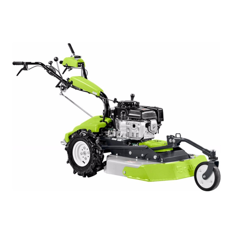
Grillo GH 9 User manual

EN
OPERATOR’S MANUAL
02511.2022.12
GH 9
Hydrostatic Multi-tool
STANDARD CONFIGURATION
WITH 85 cm ALL PURPOSE FLAIL MOWER

2
1. Introduction ............................................................................ 3
2. Description and intended use............................................... 3
3. Use and safety decals............................................................ 4
4. General safety rules............................................................... 5
5. General warnings to keep in mind........................................ 7
6. Identicationofmachinecontrolsandfunctions ............... 8
7. Identicationofmachinecomponents................................. 9
8. Technicalspecications...................................................... 10
9. Operating instructions - standard conguration with
85cmailmower ..................................................................11
9.1 Setting up the machine for use.......................................11
9.2 Checks to be carried out before starting the engine.......11
9.3 Starting the engine .........................................................11
9.4 Starting the machine.......................................................11
9.5 Work conclusion ............................................................ 12
9.6 Ordinary machine cleaning............................................ 12
9.7 Useful rules for correct use............................................ 13
9.8 Sloping terrain ............................................................... 13
10. Safety devices ...................................................................... 13
10.1 Active coupling .............................................................. 13
10.2 Stationary brake ............................................................ 13
11. Ordinary adjustments .......................................................... 14
11.1 Handlebar setting .......................................................... 14
11.2 Cutting height adjustment.............................................. 14
12. Extraordinary adjustments.................................................. 15
12.1 Adjusting the turn levers ................................................ 15
12.2 Adjusting the forward lever ............................................ 15
12.3 Adjusting the PTO lever................................................. 15
12.4 Adjusting the handlebar rotation lever ........................... 15
12.5 Adjustingtheailmowerbelttension ............................ 15
13. Ordinary maintenance ......................................................... 16
13.1 Engine maintenance...................................................... 16
13.2 Maintenance of the hydrostatic axle .............................. 16
13.3 Maintenanceoftheailmower...................................... 17
14. Extraordinary maintenance................................................. 18
14.1 Replacing the hydrostatic axle belt................................ 18
14.2 Replacing the PTO belts................................................ 18
14.3 Replacingtheailmowerdrivebelt............................... 18
15. Troubleshootingguide......................................................... 19
16. Maintenanceschedule......................................................... 20
17. Lubricationchart.................................................................. 20
18. Storage and prolonged inactivity ....................................... 21
19. Availableattachments.......................................................... 21
20. Technicalassistanceservice .............................................. 22
20.1 Assistance ..................................................................... 22
20.2 Identicationdata .......................................................... 22
20.3 Spare parts .................................................................... 22
20.4 Warranty ........................................................................ 22
20.5 How to order spare parts ............................................... 22
21. Transport warnings.............................................................. 22
22. Disposal ................................................................................ 22
Declaration of Conformity............................................................ 23
Translationoftheoriginalmanual.
Allinformation,illustrationsandtechnicalspecicationsinthis
manualarebasedonthelatestinformationavailableatthetime
of publication.
Subjecttochangewithoutpriornotice.
TABLE OF CONTENTS
GH 9 Hydrostatic Multi-tool / Translation of the original instructions

3
1. INTRODUCTION
Dear Customer,
we thank you for the trust and preference you have placed in our Grillo
GH9allpurposeailmowerandwearecondentthattheuseofyour
new machine will fully meet your requirements.
For optimal use and maintenance over time, please carefully read and
follow the instructions in this booklet; this will enable you to obtain the
best results and safeguard your purchase.
Please keep this manual, which should always accompany the machine
as an integral part of it.
Readingtheoperator’smanualisveryimportant.
2. DESCRIPTION AND INTENDED USE
The GH 9 is a hydrostatic multi-tool, a self-propelled agricultural machine
equipped in the standard version with a 85 cm ail mower for cutting
grass in rustic areas even on sloping surfaces (max 20°).
The machine consists of a supporting frame, on which is installed an
internal combustion engine that drives the wheels and a PTO where the
attachment(inthestandardversiona85cmailmower)isconnected.
Attachmentssuchasa68cmallpurposeailmower,132cmprodouble
blade cutter bar, 100 cm sweeper, 100 cm snow blade, 70 cm two-stage
snow thrower, weed brush can be attached.
The machine is controlled by an operator on the ground who follows its
movement by guiding it via a handlebar, on which the controls are located.
Any other use is considered as improper use.
This machine must only be used by personnel who are familiar with
its specic features, safety regulations and all that concerns accident
prevention.
Any improper use of the machine will invalidate the warranty and relieve
the manufacturer of all responsibility; any risk resulting from improper use
will be borne by the user.
Maintenanceandrepairofthemachinemustbecarriedoutbyqualied
personnel following the procedures specied by the manufacturer.
Any alteration or tampering will invalidate the warranty and relieve the
manufacturer of all responsibility for damage or accidents.
mArkings in the mAnuAl
This manual contains warnings highlighted in bold and marked with these
symbols:
CAUTION
This symbol and the text that follows it contain information that
highlights possible, even very serious, risks to the safety of the
operatorandanyoneworkingonthemachineiftheydonotconsider
thewritteninformationandprocedures.
IMPORTANT
This heading informs the operator of actions or conditions that
coulddamagethemachine.
Read these messages carefully to avoid injury or damage to the machine.
The retailer is responsible for inspecting the machine before delivery and
for completing the inspection form “PRE-DELIVERY INSPECTION”.
On this occasion the retailer will provide the customer with all the
information necessary to use the machine.
The customer will receive the machine in optimum condition.

4
3. USE AND SAFETY DECALS
Forward lever and
PTO engagement
Parking brake
Serial number
Consult the
manual
Danger
of bursting
Danger -
disconnect
the spark plug
before doing any
maintenance
Danger
of gas inhalation
Danger -
transmission parts
Danger -
thrown objects,
keep a safe
distance
Danger - sharp parts
Fire hazard
Danger of burns
Forward gear
Reverse gear
STOP position

5
4. GENERAL SAFETY RULES
Accident prevention rules
On the machine and in this manual there are warnings and indications
accompanied by this symbol:
it indicates the presence of a potential hazard for which particular caution
should be taken for your own safety and for the safety of others who may
be within the operating range of the machine.
All accident prevention rules in this manual are important and must be
observed. Always keep the manual handy and read it carefully to learn
how to use the machine safely. Do not allow anyone to use the machine
without having received comprehensive instructions.
explAnAtion of wArning decAls
Risk of injury
Before doing any maintenance, disconnect the spark plug and read the
instruction manual.
Danger of bursting
Rim separation or tyre bursting can cause serious injury or even death. Be
sure to maintain tyre pressure at the level recommended in this manual,
excessive pressure can cause the tyre to burst.
If a tyre is damaged or cut, do not use it, it could burst. To replace or repair
it, contact a specialised centre.
Danger of burns
Take particular care not to come into contact with hot engine parts.
Dangerofgasinhalation
Exhaust fumes can cause serious damage to health or death.
If it is necessary to start the engine in an enclosed space, use an
extension piece to the exhaust pipe to blow out the smoke. Work in a well
ventilated area.
Dangerofre
Handlefuelwithcareasitishighlyammable;donotrefuelwhilesmoking,
nearopenamesorsparks,whentheengineisrunning.
Dangerofinjuryfromsharpknives
Do not put hands or feet under the all purpose ail mower when the
engine is running.
Dangerofthrownobjects,keepasafedistance
Donotworkwiththeallpurposeailmowerongravelorforeignbodies
that can be thrown at a distance and be very dangerous.
Keep people at least 15 m away when the machine is running.
Risk of injury caused by transmission parts
When the engine is running, never touch pulleys or belts, do not carry out
maintenance and keep hands away from the indicated area.

6
personAl protection equipment
Before using the machine the appropriate personal protection equipment
must be worn: body protection, protective gloves, safety footwear, hearing
protection, goggles.

7
5. GENERAL WARNINGS TO KEEP IN MIND
WARNING:Readcarefullybeforeoperatingthemachine.
Cautionisthemainrequirementinaccidentprevention!Carefully
read the following warnings when using the machine, even
before starting work. Improper use can be dangerous. Observe
thefollowingprecautions:
• Read this manual completely before starting and running the
machine;
• Before handing the machine over to other people, make them
aware of the safety rules and how to use the machine;
• Pay particular attention to the safety decals on the machine;
• When working with the all purpose ail mower (or other
optional attachments) always wear appropriate work clothes,
long trousers, gloves, safety footwear, goggles; avoid wearing
clothing or accessories that can get caught in the controls or in
theailmower(e.g.loosetrousers,scarves,etc.);
• The use of hearing protection equipment is recommended when
using the machine continuously. Use earplugs or earmuffs that
comply with current regulations.
sAfety in the working environment
• Before switching on the machine, check that there are no
animals or people nearby, especially children; the minimum
distance is 15 m;
• Check the area where the machine is to be used: before starting
work, remove all objects that could damage the knives or that
could be thrown from the rotating tool (e.g. stones);
• Take care when working near a road, when there are passers-
by;
• Do not work near ditches or embankments that may collapse
under the weight of the machine, especially if the surface is
uneven or wet;
• Be particularly careful when working on slopes, take special
care when changing direction, do not work on excessively steep
slopes (max 20°). The machine’s manoeuvrability is reduced on
slopes;
• Be very careful when reversing, in case of danger let go of the
handlebar, the machine will stop immediately;
• It is dangerous to operate the levers sharply with the engine at
maximum speed;
• To avoid toxic exhaust fumes, do not use the machine in
enclosed spaces.
driving And behAviourAl sAfety
• Do not use the machine to transport people or animals;
• Children under 16 years of age must not use the machine;
• Donotusethemachinewhenfatiguedorundertheinuenceof
alcohol, drugs or medications that impair the operator’s physical
and cognitive abilities;
• On uneven terrain proceed at low speed;
• Onlyworkinsunlightorwithgoodarticiallight;
• Do not leave the machine on a slope;
• The machine must only ever be accompanied by walking, never
by running.
further sAfety meAsures
• If you hit a foreign body, disengage the attachment, switch off the
engine, and inspect the rotor and blades for damage;
• If the machine begins to vibrate abnormally after a knock,
immediately carry out a general check to identify the reason for
the anomaly. If necessary, request the assistance of an authorised
Grillo workshop;
• Rotationoftheailmowerrotorisverydangerous,neverputyour
hands or feet near the rotor while the engine is running;
• The guards installed on the machine (bonnets, plastics, etc.) must
not be removed when working;
• Before starting work, check that all safety devices are in working
order. Do not tamper with or deactivate them;
• Do not operate the machine barefoot; keep feet well clear of the
rotor;
• Before checking, adjusting, repairing or simply cleaning the
machine, switch off the engine;
• Do not change the engine settings, especially the maximum revs;
• Do not have anyone check the machine while you are driving with
the engine running.
fuel And fire hAzArd
• Only refuel outdoors, always switch off the engine, stay away from
sparks or ames, do not smoke! Securely replace tank and fuel
container caps;
• Avoidfuelspills.Afterllingthetankcleanupanyspillageonthe
machine before starting the engine;
• Storefuelincontainersspecicallydesignedforthispurpose;
• If it is necessary to empty the tank, do so outdoors or in a ventilated
area;
• Caution!Toreducetheriskofre,alwayskeeptheengine,mufer,
exhaust manifold, fuel tank area and fuel line clean and free of
grass, leaves and dust;
• Do not store the machine in buildings where the fuel vapours could
reachamesandsparks;
• Allow the engine to cool down before storing the machine in an
enclosed area.
sAfe replAcements
• Deformedordamagedailmowerknivesmustalwaysbereplaced,
never repaired;
• Always use genuine Grillo spare parts and accessories;
• Grillo machines are designed for the use of genuine Grillo
accessories or accessories from authorised manufacturers. Do not
install non-genuine accessories, accessories from unauthorised
manufacturers,oraccessoriesmodiedbyunauthorisedpersonnel
on your machine.

8
6. IDENTIFICATION OF MACHINE CONTROLS AND FUNCTIONS
3 4 5
1
2
7
6
8
8
10
11
9
3
5
7
6
1 4
2
12
15
14
13
1. HANDLEBAR ROTATION LEVER
2. LEFT TURN LEVER
3. FORWARD LEVER
4. PTO LEVER
5. HANDLEBAR HEIGHT ADJUSTMENT LEVER
6. RIGHT TURN LEVER
7. THROTTLE
8. SPEED CONTROL LEVER
9. MACHINE BODY SUPPORT ROD
10. FLAIL MOWER LIFTING ROD
11. LIFTING ROD HOLDER
12. CRANK FOR ADJUSTING THE CUTTING HEIGHT OF THE FLAIL MOWER
13. CRANK CATCH
14. LOCKING DEVICE FOR THE FRONT WHEELS OF THE FLAIL MOWER
15. KNOB FOR ADJUSTING THE HARDNESS OF THE SPEED CONTROL LEVER

9
1. ENGINE AIR FILTER
2. CHOKE LEVER
3. FUEL TAP
4. PARKING BRAKE PEDAL
5. RECOIL KNOB
6. ENGINE GUARD
7. ENGINE FAN GRID
8. FUEL TANK CAP
9. LEFT-HAND ENGINE OIL LEVEL AND TOP-UP PLUG
10. ENGINE OIL DRAIN PLUG
11. HANDLEBAR DAMPER
12. RIGHT-HAND ENGINE OIL LEVEL AND TOP-UP PLUG
13. PROTECTIVE GUARD
14. FLAIL TRANSMISSION AND BELT
7. IDENTIFICATION OF MACHINE COMPONENTS
2
1
4
3
5
7
8
6109
13
14
11
12

10
8. TECHNICAL SPECIFICATIONS
MODEL: GH 9 Multi-tool, standard conguration with 85 cm all
purposeailmower.
ENGINE: Honda GX 270, 270 cm³, 6.3 kW (8.4 HP) at 3600 rpm, single-
cylinder petrol engine.
FUEL TANK CAPACITY: 5,3 litres
STARTER: breakaway with recoil starter.
TRANSMISSION: hydrostatic.
SPEED: 0 to 6 km/h continuously variable, reverse gear 0 to 3 km/h.
DRIVING SYSTEM: lever steering with traction disengagement on the
wheel axle.
HANDLEBAR: adjustable in height and sideways, foldable.
DRIVING WHEELS: with 16x6.50-8 tyres.
FRONT WHEELS (all purpose ail mower attachment): solid and
puncture-proof.
SAFETY DEVICE: active coupling (immediate stop of the attachment
when the lever is released).
PARKING BRAKE: pedal-operated.
PTO: at 965 rpm anticlockwise.
CUTTING SYSTEM: rotor with Y-shaped knives.
FLAIL ROTOR SPEED: 2400 rpm
FLAIL ROTOR DIAMETER: 29.5 cm
CUTTING WIDTH: 85 cm
CUTTING HEIGHT: crank adjustable from 3 to 11 cm.
DIMENSIONS(completewith85cmallpurposeailmower)
- Max handlebar width (A): 70 cm
- Flail mower width (B): 97 cm
- Width at the wheels (C): 68 cm
- Machine body length (D): 106 cm
- Total length (E): 200 cm
- Height (F): 97 cm
WEIGHT(completewith85cmallpurposeailmower): 165 kg
WEIGHT(machinebodyonly): 88 kg
AVAILABLE ATTACHMENTS:
-68cmallpurposeailmower;
- 132 cm pro double blade cutter bar;
- 100 cm sweeper;
- 100 cm snow blade;
- 70 cm two-stage snow thrower;
- Weed brush.
A
C
B
D
E
F
Fig. 1

11
9. OPERATING INSTRUCTIONS - STANDARD
CONFIGURATION WITH 85 CM FLAIL MOWER
9.1 SETTING UP THE MACHINE FOR USE
• Check the integrity of the machine to ensure that it has not been
damaged during transport;
• Remove the machine from its packaging, taking care not to damage
the levers and cables. Use an appropriate hoist with a minimum
load capacity of 200 kg;
• Raise the handlebar to the driving position using the height
adjustmentlever(g.2/5);
• Stabilise the machine body in a horizontal position by lowering the
supportrodttedtothebumper(g.2/9)andsecureitbytightening
the knob;
• Removetheailmowerfromitspackaging,inserttheailmower
liftingrodintotheholeprovidedasshowning.2/a(thepinmust
be engaged - if the hole does not align, use the adjusting crank to
help).Atthispointtheailmowerisatthesamelevelasthexing
screwsonthemachinebody.Fititandtightenthexingnuts(g.
3); raise the support rod connected to the bumper and lock it in this
position;
• Check the tyre pressure (16x6.50-8 2PLY RATING) it must be 1.2
bar.
Flail mower
Machine body
5
9
Fig. 2 a
Fig. 3
9.2 CHECKS TO BE CARRIED OUT BEFORE
STARTING THE ENGINE
Before using the machine, always check that:
1. The engine oil is level (follow the appropriate booklet). There
are two oil plugs, the photo (g. 4) shows the one that is most
accessible. For a detailed oil level check see chapter 13. Ordinary
Maintenance;
2. Theintakegridsforenginecoolingareclean(g.7/7);
3. Theinsideoftheworkingframeiswellcleaned(g.5);
4. All levers are in the neutral position;
5. The PTO is disengaged;
6. Theairlter(oil-bathversion,g.7/1)iscleanandtheoilislevel;
7. Thereissufcientfuelinsidethetank;useafunnelwithaveryne
ltertollthefueltank.
Fig. 5Fig. 4
01
Fig. 6
5
2
1
3
7
Fig. 7
9.3 STARTING THE ENGINE
1. Openthefueltap(g.7/3);
2. Setthethrottletothehalfwayposition1(g.6/1)andiftheengine
iscoldactivatethechoke(g.7/2);
3. Starttheenginebyrmlypullingtherecoilstarterknob(g.7/5);
4. Oncetheenginehasstarted,movethechokelever(g.7/2)tothe
starting position.
9.4 STARTING THE MACHINE
CAUTION: before starting work, always wear appropriate work
wear,gloves,safetyshoesandgoggles.
1. Adjust the handlebar height by releasing the handlebar lever under
thecentralfairing(g.8/5);
2. To rotate the handlebar, press the lever on the left-hand side under
thehandlebargrip(g.8/1),rotatethehandlebartotherightorleft
and then release the lever to lock the position. This adjustment can
be useful when working, for example, close to a hedge or an edge
with shrubs;
3. Settheheightoftheailmower;removethecatch(g.9/13)and
adjustthecuttingheightbyturningthecrank(g.9/12).Theheight
ranges from a minimum of 3 cm to a maximum of 11 cm.
CAUTION:theheightadjustmentoftheailmowermustalways
bemadewiththeengineswitchedoff.

12
5
1
Fig. 8
Fig. 9
13
12
4. Now start the engine (see 9.3 Starting the Engine);
5. Setthespeedcontrollever(g.10/8)intheSTOPposition;
6. Lowertheforwardlever(g.10/3)andgentlyoperatethespeed
control lever (g. 10/8). By pushing it forward, the machine will
move forward and the speed will increase continuously as the lever
moves forward (be very careful when handling this manoeuvre,
you must become familiar with the lever). Reversing is achieved by
pulling the speed control lever towards you;
RM
26
STOP
83 4
Fig. 10
CAUTION:Withtheforwardlever(g.10/3)presseddown,both
forwardand reversetravelcanbemanagedvia thespeedcontrol
lever(g.10/8)withoutdiscontinuity.Itisrecommendedtohandle
themovementsofspeedcontrollevergentlyandsmoothlywithout
sudden jerks.
7. Practice forward and reverse travel only to familiarise yourself with
the machine;
8. Then familiarise yourself with steering manoeuvres to the right
or left by operating the levers on the handlebars. As you move
forward,pressingtherightturnlever(g.10/6)willdisengagethe
right wheel and the machine will tend to turn right; pressing the left
turnlever(g.10/2)willdisengagetheleftwheelandthemachine
will tend to turn left;
CAUTION:byreleasingtheforwardlever(g.10/3)themachine
stops.
CAUTION:whenthePTOlever(g.10/4)ispointingtowards
thefrontofthemachinethePTOisdisengagedandtheattachment
isstopped,whentheleverispointingtowardstheoperatorthePTO
isengagedandtheattachmentrotates.
9. Tooperate theailmower,thethrottle levermustbeinhalf-way
position1(g.6/1)andthespeedcontrollever(g.10/8)mustbe
inSTOP.Holddowntheforwardlever(g.10/3)withyourlefthand,
engagethePTOlever(g.10/4)andtheailmowerwillstarttorun.
Move the throttle to maximum speed, then use the speed control
lever to select the appropriate speed and begin work.
CAUTION:byreleasingtheforwardlever(g.10/3)themachine
stopsandthePTOlever(g.10/4)returnstotheSTOPposition:this
isasafetyfeaturethatallowstheoperatoratanytimetostopthe
machinecompletely.
CAUTION: when the engine is running, never put hands or
feetinthecuttingarea.Maintainallguardstoallowsafeuseofthe
machine.
9.5 WORK CONCLUSION
Onceworkisnished,stoptheenginebyreleasingtheforwardlever(g.
10/3)andturnthethrottletoposition0(g.6/0),thenclosethefueltap
(g.7/3).
CAUTION:neverleavethemachineunattendedand/orwithin
reachofchildrenorpeoplewhohavenotreadthismanualorwho
havenotreceivedadequateinstructionsforthesafeandproperuse
ofthehydrostaticailmower.
IMPORTANT:tomovethemachinewhentheengineisstopped,
bothleftandrightturnlevers(g.10/2and10/6)mustbepressed
simultaneouslyasthisdisengagesthedrive.
9.6 ORDINARY MACHINE CLEANING
CAUTION: before starting any cleaning work, always wear
suitableclothingandprotectivegoggles.
CAUTION:whencleaningthecuttingrotor,alwaysensurethat
themotorisswitchedoff.
CAUTION:inordertoreducetheriskofre,itisimportantto
keeptheengineandmuferareawellcleanedofdustanddrygrass
residuesandtoallowthe engine to cool down beforestoringthe
machineinanenclosedarea.
At the end of each job, proper cleaning ensures a long service life for the
machine and prevents most common inconveniences.
The best way to clean the machine is with compressed air in the engine
areaandoptionallywaterforthebodypartsandtheailmowerarea.
IMPORTANT: avoid wetting the engine linkages, cables and
handlebarleverswithastrongjetofwater.

13
9.7 USEFUL RULES FOR CORRECT USE
The machine will work in optimum condition if certain precautions are
followed.
• Before starting work, check that the attachment is clean, free of
grass and dirt;
• Always keep cables and levers clean of dirt and dust;
• Before starting work, check the ground for stones, large branches
and foreign bodies. If possible, remove them;
• Be careful if the engine revs drop: you are working overloaded,
you must reduce the forward speed. Never force the engine: when
smoke comes out of the exhaust it is overloaded, you must slow
down;
• Never leave the machine under the rain;
• Check the knives of the ail mower frequently (g. 5), ensure
that they are free to rotate, if worn, turn them and replace them if
necessary:thenishoftheworkwillbebetterandtheenginewill
absorb less power;
• During work keep the engine at maximum revs, adjust the speed
according to the height of the grass to be shredded;
• Keeptheenginegridsclean(g.7/7);
• Check frequently the tyre pressure.
9.8 SLOPING TERRAIN
Be careful when working on slopes, the manoeuvrability of the machine
is reduced.
CAUTION:avoidslopesthataretoosteep;forcorrectmachine
operationandsafety,observe the slope limitsof the engine: max
20°.
Steep terrain should be negotiated if possible in the uphill/downhill
direction, taking great care when changing direction and that the uphill
wheel does not encounter any obstacles (stones, branches, roots, etc.)
that could cause the machine to tip over or lose control. Therefore, assess
the various situations and be careful on wet ground and wet grass, as the
machine could slip.
When going downhill, start at low speed.
CAUTION:onslopingterrain,avoiddisengagingdrivetothe
wheelsbypressingbothturnlevers(g.10/2and10/6)atthesame
timeasthemachinewillrunawaydownhillwithoutcontrol.
10. SAFETY DEVICES
10.1 ACTIVE COUPLING
The machine is equipped with an active coupling system.
Releasingtheforwardlever(g.10/3)causesthemachinetostopand
thePTOlever(g.10/4)toreturntotheSTOPposition;thisisasafety
feature that allows the operator at any time to stop the attachment and the
forward/reverse travel of the machine.
CAUTION:checkfrequentlythattheactivecouplingfunctions
correctly.Whentheforwardlever(g.10/3)isreleased,themachine
must stop immediately.
10.2 STATIONARY BRAKE
To park the machine correctly, the pedal brake must be engaged.
Inthepositioning.11thebrakeisdisengaged,inthepositioning.12
the brake is engaged.
Always apply the parking brake when leaving the machine on a slope or
during transport.
Fig. 11 Fig. 12

14
11. ORDINARY ADJUSTMENTS
11.1 HANDLEBAR SETTING
Before starting work, it is recommended to position the handlebar in the
most comfortable position and with the greatest control over the machine.
To adjust the height of the handlebar, push down the lever located at the
baseofthehandlebar(g.13/5),thenmovethehandlebarupordown.To
lock the handlebar in the desired position, release the lever, ensuring that
its central pin engages in the notch.
5
Fig. 13
In certain cutting conditions, such as clearing edges, it may be useful
to rotate the handlebar to the right or left. To rotate it, simply use the
appropriatelever(g.14/1):bypressingit,thehandlebarcanrotatefreely
and it will be possible to move it to the right or left.
By releasing the lever, the column will lock into the holes in the base.
8
1
15
Fig. 14
Thehardnessofthespeedcontrollever(g.14/8)locatedinthecentre
of the handlebar housing can also be adjusted by simply tightening or
looseningtheknob(g.14/15).
11.2 CUTTING HEIGHT ADJUSTMENT
Tosetthecuttingheightoftheailmower,removethecatch(g.15/13)
and turn the crank (g. 15/12) clockwise/counterclockwise to set the
desired height, then reposition the catch.
The height ranges from a minimum of 3 cm to a maximum of 9 cm.
Fig. 15
13
12
14
Fig. 16
Theadjustment crankhasamechanismhinged toaspecicholewith
a nut and screw (g. 16); the two free holes are only used when the
scarifyingkit(optionalpurchasedseparately)isttedtotheailmower.
Theswivelwheelsontheailmowercanalsobelocked.Onthesupport
ofeachwheelthereisarigidrubberinsertwithasmallpin(g.16/14).By
pushing down on the insert by hand, the pin is inserted into a hole in the
forktolockitsposition,sothattheailmowerwillonlymoveinastraight
line. This can be very useful when working in a hillside. To return to free
wheels unlock the plastic insert by pulling it upwards releasing the pin.
CAUTION:theheightadjustmentoftheailmowermustalways
bemadewiththeengineswitchedoff.

15
12. EXTRAORDINARY ADJUSTMENTS
CAUTION: The adjustment procedures described below
requiretechnicalskillsandexpertise.Itisadvisabletocontactan
authorisedGrillocentretocarrythemout.
Keeping the levers at the correct tension ensures proper operation of the
machine controls. The tension of the connected cable can be adjusted
for each lever.
Before any adjustment, carry out a visual check of the machine.
12.1 ADJUSTING THE TURN LEVERS
Whenpressingtherightturnlever(g.17/6)theright-handwheelshould
disengage from the transmission; if this does not happen, loosen the lock
nut(g.17/B)andslightlyextendtheadjuster(unscrewit),thenretighten
the lock nut.
Inthesamewaytheleftturnlever(g.17/2)canbeadjustedwiththeleft
turnleveradjuster(g.17/A).
2 6
AB
Fig. 17
12.2 ADJUSTING THE FORWARD LEVER
Ifthemachinedoesnotmovewhentheforwardlever(g.18/3)islowered,
itisnecessarytoloosenthelocknut(g.18/C)andslightlyextendthe
adjuster (unscrew it), then retighten the lock nut. If, on the other hand,
the machine moves despite the forward lever being lifted, it is necessary
to loosen the lock nut and shorten the adjuster slightly (screw it in), then
retighten the lock nut.
3
C
Fig. 18
12.3 ADJUSTING THE PTO LEVER
IftheailrotordoesnotstartwhenthePTOlever(g.19/4)isoperated,
itisnecessarytoloosenthelocknut(g.19/D)andslightlyextendthe
adjuster (unscrew it), then retighten the lock nut.
If,ontheotherhand,theailrotordoesstartdespitethePTOleverbeing
released, it is necessary to loosen the lock nut and slightly shorten the
adjuster (screw it in), then retighten the lock nut.
4D
Fig. 19
12.4 ADJUSTING THE HANDLEBAR ROTATION
LEVER
If the pin that locks the handlebar is not released when the handlebar
rotationlever(g.20/1)ispressed,itisnecessarytoloosenthelocknut
(g.20/E)andslightlyextendtheadjuster(unscrewit),thenretightenthe
lock nut.
E1
Fig. 20
12.5 ADJUSTING THE FLAIL MOWER BELT TENSION
Regularlycheckthebelttensionofthesidedrivebeltoftheailmower
(every 10 hours).
Todothis,removethesidecoveroftheailmower(g.21).
Fig. 21
Forcorrectbelttension,theredarrowtip(g.22/F)mustbealignedwith
the washer under the tightening nut; if the arrow is not in the correct
position,itisnecessarytoloosenthelocknut(g.22/G)andscrewor
unscrewthetighteningnut(g.22/H)untilthearrowtipisinthecorrect
position, then retighten the lock nut.

16
H
G
F
Fig. 22
13. ORDINARY MAINTENANCE
CAUTION: always use suitable tools such as supports and
safetydevicesifthemachineorpartofithastobelifted.
• Alwayswearsuitableclothingandworkglovesbeforestarting
anycleaning,maintenanceorrepairwork;
• Donotleavethemachineduringmaintenancewithoutsafety
devices or lifted, in places accessible to inexperienced people,
especiallychildren;
• Neverdisposeofusedoil,fuelandanyotherpollutantsinto
theenvironment!
• Regular maintenance helps to keep the machine in perfect
working order.
CAUTION: before carrying out all control and maintenance
operation,makesurethattheengineisswitchedoff.
13.1 ENGINE MAINTENANCE
IMPORTANT: read the engine manual; check the engine
periodically,keeptheairltercleanandtheengineoillevel.
IMPORTANT: place the machine in a horizontal position to
checkuidlevels.
engine Air filter
Checkandcleantheairlterevery10hours.
Forengineswithanoil-bathairlter(g.7/1),changetheoilifdirty.Use
the engine oil recommended in the engine manual.
engine oil
IMPORTANT:itisessentialtochangetheengineoilafterthe
break-inperiod(rst20hours).Thenchangetheoilevery100hours
or once a year.
The engine must be cold and in a horizontal position to check the engine
oil level.
Removethellingplug/dipstickandcleanit(g.23).
Reinsertandremovethedipstickwithoutscrewingitintothellerneck:
the oil level will be marked on the dipstick.
If the oil level is low, top up to the edge of the ller neck with the
recommended oil; see the engine manual for further instructions.
To change the engine oil, follow the instructions in the engine manual.
Fig. 23
13.2 MAINTENANCE OF THE HYDROSTATIC AXLE
Change the hydrostatic axle oil every 50 working hours.
For optimum performance it is recommended to use the specic GH
axle oil available from Grillo dealers. To change the oil it is necessary to
disassemble the axle, the procedures described below require technical
skills and expertise, it is advisable to contact an authorised Grillo centre.
1. Remove the axle from the machine;
2. Unscrewtheplug(g.24/I);
3. Raise the levers (g. 24/L) by 2 cm, using a thin screwdriver to
release the locking tabs;
4. Drain all the oil;
5. Clamp the axle in a vice;
6. Undothesixbolts(g.25/M)andopentheaxle;
7. Thoroughlycleanthe magnet (g.26/N) and the housingofany
metal residue;
8. Reassemble the axle, taking care to reposition all parts correctly;
9. Close the cover, taking care to correctly reinsert the two plastic pins
intotheholesintheplasticforks(g.26/O);
10. Tightenallcoverbolts(g.25/M);
11. Keepthelevers(g.24/L)liftedup;
12. Fill the axle with 1.8 L of oil Grillo code 53140 or gearbox oil 10W60;
13. Lowerthelevers(g.24/L)untiltheyclickintoplaceandtightenthe
oilplug(g.24/I).
LL
I
Fig. 24

17
M
M
Fig. 25
O
Fig. 26 N
13.3 MAINTENANCE OF THE FLAIL MOWER
mAintenAnce position of the flAil mower
Itispossibletoservicetheailmowerbyraisingitandkeepingitina
stable position by placing the lifting support rod in the appropriate holder.
CAUTION: all maintenance work on the ail mower must be
carried out with the engine switched off and the parking brake
applied.
Fig. 27
lubricAting the trAnsmission
Remove the upper metal protection by unscrewing the 4 screws that
secureit(g.28).Changethetransmissionoilevery50workinghours.
Use IP MELLANA 220 gearbox oil, quantity: 0.2 litres.
Fig. 28
greAsing the rotor And front wheel beArings
Greasethebearingsoftheailmowerrotorandthecarriagefrontwheels
every20operatinghoursusingthegreasenipples(g.29).
Thegreasenipplesonthewheelsareidentiedbyadedicateddecal.
Fig. 29

18
14. EXTRAORDINARY MAINTENANCE
CAUTION: replacement of the belts below should only be
carriedoutifthebeltsareexcessivelyworn,brokenorhaveevident
cracks.ItisadvisabletocontactanauthorisedGrillocentretohave
thebeltsreplaced.
14.1 REPLACING THE HYDROSTATIC AXLE BELT
To replace the hydrostatic axle belt, it is necessary to:
1. Remove the plastic guards;
2. Loosen the two grub screws connecting the transmission shaft to
theengineshaft(g.30);
3. Loosen the screws that secure the engine to the frame and then
move the engine back until there is enough clearance to pass the
belt through;
4. Replace the worn belt with a new original Grillo belt;
5. Reassemble all components, taking care to align the pulleys;
6. Tightenallboltsandrettheplasticguards;
7. If necessary, adjust the belt tension using the appropriate adjuster
(see chapter 12.2 Adjusting the forward lever).
Fig. 30
14.2 REPLACING THE PTO BELTS
To replace the PTO belts, it is necessary to:
1. Remove the plastic guards.
2. Removethebeltguidebracketlocatedabovethesmallpulley(g.
31);
3. Replace the worn belts with a new pair of original Grillo belts;
4. Retthebeltguide;
5. Tightenallboltsandrettheplasticguards;
6. If necessary, adjust the belt tension using the belt tension adjuster
(see chapter 12.3 Adjusting the PTO lever).
Fig. 31
14.3 REPLACING THE FLAIL MOWER DRIVE BELT
Toreplacetheailmowerdrivebelt,itisnecessaryto:
1. Toreplacetheailmowerdrivebelt,itisnecessaryto:
2. Removetheguardlocatedontherightsideoftheailmower(g.
21);
3. Loosen the tensioner by unscrewing the nuts located above the tie
rod(g.32);
4. Replace the worn belt with a new original Grillo belt;
5. Adjust the tension of the tensioner (see chapter 12.5 Adjusting the
ailmowerbelttension);
6. Rettheguardontherightsideoftheailmower.
Fig. 32

19
15. TROUBLESHOOTING GUIDE
GH 9 WITH FLAIL MOWER - TROUBLESHOOTING GUIDE
PROBLEM CAUSE SOLUTION
The engine does not start
Out of fuel - Check that the fuel tap is open
- Check the fuel level
Throttle is set to zero - Move the throttle to position 1
Combustion issues
- Check that the choke is applied (if the engine is cold)
- Check that the hole in the tank cap is not blocked
- Check that the carburettor jets are clean
- Check that the spark plug gives a spark
The engine starts but the
machine does not move
forward
The speed control lever is in the neutral position - Move the lever forward or backward to select the
desired speed
Insufcientcabletensionoftheforwardlever - Act on the forward lever adjuster, increasing the tension
of the connected cable (see chapter 12.2)
The machine moves
forward even if the forward
lever is not pressed
Excessive cable tension on the forward lever - Act on the forward lever adjuster, decreasing the
tension of the connected cable (see chapter 12.2)
The engine starts but
theailmowerdoesnot
operate
InsufcientcabletensionofthePTOlever - Act on the PTO lever adjuster, increasing the tension of
the connected cable (see chapter 12.3)
Flail mower drive belt tension - Adjusttheailmowerbelttension(seechapter12.5)
The engine does not
switch off
Throttle not in zero position - Move the throttle to the zero position
Throttle not properly connected to the engine - Check the throttle and its connection to the engine
Drop in engine
performance during cutting Overload
- Proceed with cutting small areas, avoiding cutting in
areas with many residual shrubs
- Raise the cutting height
The PTO engages even
if the PTO lever is in the
STOP position
Excessive cable tension of the PTO lever - Act on the PTO lever adjuster, decreasing the tension
of the connected cable (see chapter 12.3)
The engine switches off
whenactivatingtheail
mower
Insufcientenginepoweroutput - Increase power from the throttle
Rotor jammed by an obstruction or wound grass - Checkforobstructionsblockingtheailmowerand
remove them
CAUTION:Ifproblemspersistaftercarryingouttheactions
describedinthismanual,contacttheauthorisedservicecentre.
Never attempt to carry out major repairs without having the
necessarymeansandtechnicalexpertise.
IF YOU HIT A STONE OR ANOTHER FOREIGN BODY
1. Disengage the cutting rotor;
2. Switch off the engine;
3. Pull out the lifting support rod;
4. Tilt the machine, raising the cutting rotor;
5. Insert the lifting support rod into the appropriate holder;
6. Check the integrity of the rotor and blades.

20
16. MAINTENANCE SCHEDULE
GH 9 WITH FLAIL MOWER - MAINTENANCE SCHEDULE
MAINTENANCE ITEM AT EVERY USE
WHICHEVER OCCURS FIRST
FIRST 20 HOURS
OR WITHIN THE
FIRST MONTH
EVERY 50 HOURS
OR 6 MONTHS
EVERY 100 HOURS
OR EVERY YEAR
Engine oil Check the level ●
Change ● ●
Airlter Check ●
Replace *
Flail mower transmission oil Change ●
Flail mower drive belt Check the tension ●
Replace ●
Hydrostatic axle oil Change ●
Check that the engine intake grid is well cleaned ●
Checkingthesharpnessandxingoftheknives ●
Grease lubrication ● ●
Check tyre pressure (1.2 bar) ● ●
●recommended task
*task to be carried out if necessary
IMPORTANT:regularlycheckthehydrostaticaxleandtheailmowerdriveforoilleaks.
17. LUBRICATION CHART
GH 9 WITH FLAIL MOWER - LUBRICATION CHART
Engine oil SAE30 1.1 L Changeaftertherst20operatinghoursandthenevery100hoursor
once a year thereafter
Flail mower transmission oil IP MELLANA 220 0.2 L Change every 50 working hours or every 6 months
Hydrostatic axle oil GRILLO 53140
10W60 1.8 L Change every 50 working hours or every 6 months
Table of contents
Other Grillo Lawn And Garden Equipment manuals

Grillo
Grillo 978511 User manual

Grillo
Grillo G52 User guide

Grillo
Grillo CLIMBER 780 User manual

Grillo
Grillo FM13.09 User manual

Grillo
Grillo DUMPER 507 User manual

Grillo
Grillo G52 User guide

Grillo
Grillo DUMPER 406 User manual

Grillo
Grillo CLIMBER 9.27 User manual

Grillo
Grillo 2500 User manual

Grillo
Grillo gf2 User manual
Popular Lawn And Garden Equipment manuals by other brands

SNOWJOE
SNOWJOE Sun Joe SBJ6-GA manual

Everbloom
Everbloom E283612 installation guide

P3 International
P3 International Sonic Molechaser P7900 Specifications

Parkside
Parkside PTUS 1 A1 Operation and safety notes

Plast-IQ
Plast-IQ U-GREENY VERTICAL GARDENING SYSTEM instruction manual

breviglieri
breviglieri b45f 125 manual