Grizzly G0632 User manual

COPYRIGHT © APRIL, 2007 BY GRIZZLY INDUSTRIAL, INC.
WARNING: NO PORTION OF THIS MANUAL MAY BE REPRODUCED IN ANY SHAPE
OR FORM WITHOUT THE WRITTEN APPROVAL OF GRIZZLY INDUSTRIAL, INC.
#TS8724 PRINTED IN CHINA
MODEL G0632
16" X 42" VARIABLE SPEED
WOOD LATHE
OWNER'S MANUAL


Table of Contents
INTRODUCTION ............................................... 2
Foreword ........................................................ 2
Contact Info ................................................... 2
Machine Data Sheet ...................................... 3
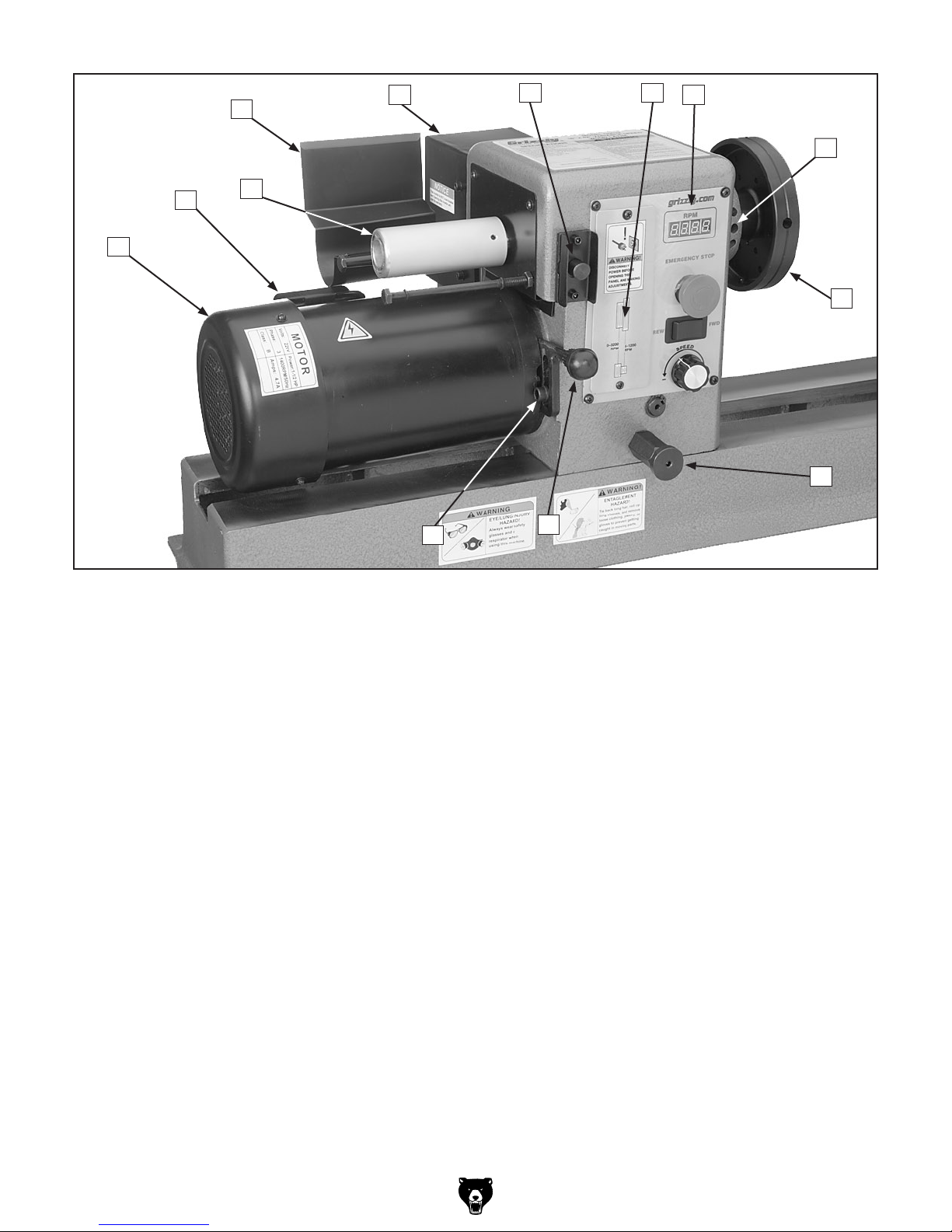
Identification ................................................... 5
SECTION 1: SAFETY ....................................... 8
Additional Safety Instructions for Wood Lathes
10
SECTION 2: CIRCUIT REQUIREMENTS ...... 11
220V Single-Phase ...................................... 11
SECTION 3: SETUP ....................................... 12
Setup Safety ................................................ 12
Items Needed for Setup ............................... 12
Unpacking .................................................... 12
Inventory ...................................................... 13
Hardware Recognition Chart ....................... 14
Site Considerations ...................................... 15
Mounting to Shop Floor ............................... 15
Clean Up ...................................................... 16
Assembly ..................................................... 16
Test Run ...................................................... 18
SECTION 4: OPERATIONS ........................... 19
Operation Safety .......................................... 19
Adjusting Headstock .................................... 19
Adjusting Tailstock ....................................... 20
Adjusting Tool Rest ...................................... 21
Installing/Removing Headstock Center ........ 22
Installing/Removing Tailstock Center .......... 23
Headstock Faceplate ................................... 24
Changing Speed Ranges ............................. 25
Indexing ....................................................... 27
Selecting Turning Tools ............................... 28
Spindle Turning ............................................ 29
Faceplate Turning ........................................ 32
Outboard Turning ......................................... 33
Sanding/Finishing ........................................ 33
SECTION 5: ACCESSORIES ......................... 34
SECTION 6: MAINTENANCE ......................... 36
Schedule ...................................................... 36
Cleaning ....................................................... 36
Lathe Bed .................................................... 36
Lubrication ................................................... 36
SECTION 7: SERVICE ................................... 37
Troubleshooting ........................................... 37
Service Log .................................................. 39
Aligning Centers .......................................... 40
Changing Belt .............................................. 40
Electrical Components ................................. 41
Wiring Diagram Overview ............................ 42
Frequency Inverter Wiring Diagram ............. 43
Stand & Bed Parts Breakdown .................... 44
Headstock Parts Breakdown ....................... 46
Label Placement .......................................... 48
WARRANTY AND RETURNS ........................ 49

-2- G0632 16" x 42" Variable Speed Wood Lathe
INTRODUCTION
Foreword
We are proud to offer the Model G0632 16" x
42" Variable Speed Wood Lathe. This machine
is part of a growing Grizzly family of fine wood-
working machinery. When used according to
the guidelines set forth in this manual, you can
expect years of trouble-free, enjoyable operation
and proof of Grizzly’s commitment to customer
satisfaction.
The specifications, drawings, and photographs
illustrated in this manual represent the Model
G0632 when the manual was prepared. However,
owing to Grizzly’s policy of continuous improve-
ment, changes may be made at any time with no
obligation on the part of Grizzly.
For your convenience, we always keep current
Grizzly manuals available on our website at www.
grizzly.com. Any updates to your machine will be
reflected in these manuals as soon as they are
complete. Visit our site often to check for the lat-
est updates to this manual!
If you have any comments regarding this manual,
please write to us at the address below:
Grizzly Industrial, Inc.
C/O Technical Documentation Manager
P.O. Box 2069
Bellingham, WA 98227-2069
Email: [email protected]
We stand behind our machines. If you have any
service questions or parts requests, please call or
write us at the location listed below.
Grizzly Industrial, Inc.
1203 Lycoming Mall Circle
Muncy, PA 17756
Phone: (570) 546-9663
Fax: (800) 438-5901
E-Mail: [email protected]
Web Site: http://www.grizzly.com
Contact Info

G0632 16" x 42" Variable Speed Wood Lathe -3-
Customer Service #: (570) 546-9663 • To Order Call: (800) 523-4777 • Fax #: (800) 438-5901
Machine Data Sheet Machine Data Sheet

-4- G0632 16" x 42" Variable Speed Wood Lathe

G0632 16" x 42" Variable Speed Wood Lathe -5-
Figure 1. Model G0632 tailstock and front view.
A. Tailstock Handwheel
B. Tailstock Quill
C. Headstock
D. Headstock Lock Handle
E. Tool Rest
F. Tool Rest Base
G. Tailstock Lock Handle
H. Tailstock
I. Tailstock Quill Lock Handle
J. Tool Rest Lock Handle
K. Tool Rest Base Lock Handle
L. Lathe Bed
M. Supporting Leg
Identification
C
DE
F
L
K
J
M
AB
I
GH

-6- G0632 16" x 42" Variable Speed Wood Lathe
Figure 2. Model G0632 headstock.
A. Motor
B. Motor Wiring Junction Box
C. Spindle Handwheel
D. Spindle Handwheel Safety Cover
E. Frequency Inverter
F. Spindle Lock
G. Front Belt Access Panel
H. Control Panel
I. Indexing Pin Holes
J. Face Plate
K. Headstock Rotation Lock
L. Motor Tensioning Handle
M. Motor Mount Cap Screw
A
BC
DEFGH
J
L
K
I
M

G0632 16" x 42" Variable Speed Wood Lathe -7-
A
B
C
D
E
Figure 3. Model G0632 control panel.
A. Front Belt Access Panel—Remove this panel to access the drive belt and pulleys for changing speed
ranges.
B. RPM Readout—Shows spindle RPM.
C. Emergency Stop Button—Disconnects power to the motor when pushed in. Rotate clockwise to let it
pop out and reconnect power to the motor.
D. REV/FWD Switch—Used to reverse the spindle direction.
E. Variable Speed Dial—Varies the spindle speed from 0 RPM's to the upper limit for the selected RPM
range.
NOTICE
The frequency inverter controls on the rear
of the headstock have no effect on the oper-
ation of the lathe. Opening the frequency
inverter will void the lathe warranty and
could seriously damage the lathe. DO NOT
open the case of the frequency inverter.

-8- G0632 16" x 42" Variable Speed Wood Lathe
Safety

G0632 16" x 42" Variable Speed Wood Lathe -9-

-10- G0632 16" x 42" Variable Speed Wood Lathe
Additional Safety Instructions for Wood
Lathes
No list of safety guidelines can be complete.
Every shop environment is different. Always
consider safety first, as it applies to your
individual working conditions. Use this and
other machinery with caution and respect.
Failure to do so could result in serious per-
sonal injury, damage to equipment, or poor
work results.
Like all machinery there is potential danger
when operating this lathe. Accidents are
frequently caused by lack of familiarity or
failure to pay attention. Use this lathe with
respect and caution to lessen the possibility
of operator injury. If normal safety precau-
tions are overlooked or ignored, serious
personal injury may occur.
1. KEEPING GUARDS IN PLACE. Make
sure all guards are in place and the lathe
sits on a flat, stable surface.
2. EYE/FACE PROTECTION. Always wear
eye protection or a face shield when oper-
ating the lathe.
3. RESPIRATORY PROTECTION. Always
wear a respirator when using this machine.
Wood dust may cause allergies or long-
term respiratory health problems.
4. MOUNTING WORKPIECE. Before starting,
be certain the workpiece has been properly
embedded on the headstock and tailstock
centers and that there is adequate clear-
ance for the full rotation of the workpiece.
5. ADJUSTING TOOL REST. Adjust tool rest
to provide proper support for the turning
tool you will be using. Test tool rest clear-
ance by rotating workpiece by hand before
turning lathe ON.
6. TURNING SPEED. Select the correct turn-
ing speed for your work, and allow the lathe
to gain full speed before starting the opera-
tion.
7. USING SHARP CHISELS. Keep lathe
chisels properly sharpened and held firmly
in position when turning.
8. OPERATING DAMAGED LATHE. Never
operate the lathe with damaged or worn
parts.
9. WORKPIECE CONDITION. Always inspect
the condition of your workpiece. DO NOT
turn pieces with knots, splits, and other
potentially dangerous conditions. Make
sure joints of glued-up pieces have high
quality bonds and will not fly apart during
operation.
10. ADJUSTMENTS/MAINTENANCE. Make
sure your wood lathe is turned OFF, dis-
connected from the power source, and all
moving parts have come to a complete stop
before starting any inspection, adjustment,
or maintenance procedure.
11. STOPPING LATHE. DO NOT attempt to
stop the lathe by using your hand against
the workpiece or face plate. Allow the lathe
to stop on its own.
12. AVOIDING ENTANGLEMENT. Keep long
hair and loose clothing articles such as
sleeves, belts, and jewelry items away from
the lathe during operation.
13. FACEPLATE TURNING. When faceplate
turning, use lathe chisels on the downward
spinning side of the workpiece only.

G0632 16" x 42" Variable Speed Wood Lathe -11-
SECTION 2: CIRCUIT REQUIREMENTS
Serious personal injury could occur if you
connect the machine to the power source
before you have completed the setup pro-
cess. DO NOT connect the machine to the
power source until instructed to do so.
220V Single-Phase Plug/Receptacle Type
Recommended Plug/Receptacle .......NEMA 6-15
Grounding
In the event of an electrical short, grounding
reduces the risk of electric shock. The grounding
wire in the power cord must be properly connected
to the grounding prong on the plug; likewise, the
outlet must be properly installed and grounded.
All electrical connections must be made in accor-
dance with local codes and ordinances.
Amperage Draw
The Model G0632 motor draws the following
amps under maximum load:
Motor Draw at 220V ............................. 4.7 Amps
Circuit Requirements
The included frequency inverter takes in 220V
single-phase power and converts it to 3-phase
power for the variable speed lathe motor. We rec-
ommend connecting your machine to a dedicated
and grounded circuit that is rated for the amperage
and phase given below. Never replace a circuit
breaker on an existing circuit with one of higher
amperage without consulting a qualified electri-
cian to ensure compliance with wiring codes. If
you are unsure about the wiring codes in your
area or you plan to connect your machine to a
shared circuit, consult a qualified electrician.
220V, Single Phase Circuit ...................15 Amps
Electrocution or fire could
result if this machine is
not grounded correctly
or if your electrical con-
figuration does not comply
with local and state codes.
Ensure compliance by
checking with a qualified
electrician!
Extension Cords
We do not recommend the use of extension cords.
Instead, arrange the placement of your equipment
and the installed wiring to eliminate the need for
extension cords.
If you find it absolutely necessary to use an exten-
sion cord at 220V with your machine:
• Use at least a 16 gauge cord that does not
exceed 50 feet in length!
• The extension cord must also contain a
ground wire and plug pin.
• A qualified electrician MUST size cords over
50 feet long to prevent motor damage.
Circuit Requirements
Figure 4. NEMA 6-15 plug and receptacle.

-12- G0632 16" x 42" Variable Speed Wood Lathe
Wear safety glasses dur-
ing the entire setup pro-
cess!
This machine presents
serious injury hazards
to untrained users. Read
through this entire manu-
al to become familiar with
the controls and opera-
tions before starting the
machine!
Setup Safety
SECTION 3: SETUP
The following items are needed to complete the
setup process, but are not included with your
machine:
Description Qty
• Assistance .................................. As Needed
• Safety Glasses (for each person) .............. 1
• Level ........................................................... 1
• Measuring Tape ......................................... 1
• Wrench 17mm ............................................ 1
• Cleaning Solvent ........................ As Needed
• Shop Rags .................................. As Needed
Items Needed for
Setup
Read and understand the rest of the instructions
contained in this SETUP section before moving
and assembling the lathe.
The Model G0632 was carefully packed when it
left our warehouse. If you discover the machine
is damaged after you have signed for delivery,
please immediately call Customer Service at
(570) 546-9663 for advice.
Save the containers and all packing materials for
possible inspection by the carrier or its agent.
Otherwise, filing a freight claim can be difficult.
When you are completely satisfied with the condi-
tion of your shipment, inventory the contents.
Unpacking
The G0632 and its com-
ponents are very heavy.
Get lifting help or use
power lifting equipment
such as a fork lift to move
heavy items.

G0632 16" x 42" Variable Speed Wood Lathe -13-
Inventory
After all the parts have been removed from the
shipping containers, you should have the follow-
ing items:
Inventory: (Figures 5–7) Qty
A. Lathe Assembly
—Headstock (mounted) ............................. 1
—Tool Rest Base (mounted) ...................... 1
—Tailstock (mounted) ................................ 1
—Face Plate 6" (installed) ......................... 1
B. Supporting Legs ......................................... 2
C. Machine Feet .............................................. 4
D. Tool Rest .................................................... 1
E. Spur Center MT#2 ...................................... 1
F. Live Center MT#2 ....................................... 1
G. Hex Wrenches 3, 4, 8mm .....................1 Ea
H. Knockout Tool ............................................ 1
I. Indexing Pin ................................................ 1
J. Hardware (not shown)
—Cap Screws M10-1.5 x 25 ...................... 8
—Lock Washers 10mm .............................. 8
If any nonproprietary parts are missing (e.g. a
nut or a washer), we will gladly replace them; or
for the sake of expediency, replacements can be
obtained at your local hardware store.
B
C
D
EF
G
H
NOTICE
Some hardware/fasteners on the inventory
list may arrive pre-installed. Check mount-
ing locations before assuming that any
items from the inventory list are missing.
Inventory
Figure 6. Model G0632 inventory B.
Figure 7. Model G0632 inventory C–I.
Figure 5. Model G0632 inventory A.
A
I

-14- G0632 16" x 42" Variable Speed Wood Lathe
Hardware Recognition Chart

G0632 16" x 42" Variable Speed Wood Lathe -15-
Floor Load
Refer to the Machine Data Sheet on Page 3 for
the weight and footprint specifications of your
machine. Some residential floors may require
additional reinforcement to support both the
machine and operator.
Placement Location
Consider existing and anticipated needs, size of
material to be processed through each machine,
and space for auxiliary stands, work tables, other
machinery, and the operator when establishing a
location for your new machine. See Figure 8 for
the minimum clearance dimensions.
Children and visitors may be
seriously injured if unsuper-
vised. Lock all entrances to
the shop when you are away.
DO NOT allow unsupervised
children or visitors in your
shop at any time!
Site Considerations
Site Considerations
Figure 8. G0632 clearance dimensions.
NOTICE
We strongly recommend securing your
machine to the floor if it is hardwired to the
power source. Consult with your electrician
to ensure compliance with local codes.
Figure 9. Typical mounting fasteners for
concrete floors.
NOTICE
Anchor studs are stronger and more per-
manent alternatives to lag shield anchors;
however, they will stick out of the floor,
which may cause a tripping hazard if you
decide to move your machine.
Generally, you can either bolt your machine to
the floor or mount it on the included machine
feet. Although not required, we recommend that
you bolt your new lathe to the floor. Because this
is an optional step and floor materials may vary,
only machine feet are included with your lathe.
Whichever option you choose, it is necessary to
level your machine with a precision level.
Bolting to Concrete Floors
Lag shield anchors with lag bolts and anchor
studs (Figure 9) are two popular methods for
anchoring an object to a concrete floor. We sug-
gest you research the many options and methods
for mounting your machine and choose the best
that fits your specific application.
Mounting to Shop
Floor
Mounting to Shop Floor

-16- G0632 16" x 42" Variable Speed Wood Lathe
The unpainted surfaces are coated with a waxy
oil to prevent corrosion during shipment. Remove
this protective coating with a solvent cleaner or
citrus-based degreaser such as Grizzly’s G7895
Citrus Degreaser. To clean thoroughly, some parts
must be removed. For optimum performance
from your machine, clean all moving parts or
sliding contact surfaces. Avoid chlorine-based
solvents, such as acetone or brake parts cleaner
that may damage painted surfaces. Always follow
the manufacturer’s instructions when using any
type of cleaning product.
Clean Up
Figure 10. Grizzly citrus degreaser.
G7895—Grizzly Citrus Degreaser
This natural, citrus-based degreaser is a great
solution for removing export grease, and it’s much
safer to work around than nasty solvents.
Gasoline and petroleum
products have low flash
points and can explode or
cause fire if used to clean
machinery. DO NOT use
these products to clean
the machinery.
Many cleaning solvents are
toxic if inhaled. Minimize
your risk by only using
these products in a well
ventilated area.
Clean Up
Assembly
To assemble your lathe:
1. Stand the right and left supporting legs up
approximately 47" apart, and get them rea-
sonably aligned, as shown in Figure 11.
The G0632 and its com-
ponents are very heavy.
Get lifting help or use
power lifting equipment
such as a fork lift to move
heavy items.
Figure 11. Stand legs approximately 47" apart to
prepare for mounting the lathe.
2. Using the help of assistants, carefully lift the
lathe onto the stands and align the mounting
holes.
Note: The headstock end of the lathe is the
heaviest and usually requires two people for
lifting that end.

G0632 16" x 42" Variable Speed Wood Lathe -17-
3. Secure the lathe assembly to the supporting
legs with the (8) M10-1.5 x 25 cap screws
and 10mm flat washers (see Figure 12).
Figure 12. Securing lathe assembly to
supporting legs.
4. If you are bolting your lathe to the floor, skip
to Step 7. Otherwise, move the tailstock, tool
rest assembly, and headstock to one end of
the lathe bed (see the OPERATIONS sec-
tion beginning on Page 18 for instructions for
moving these components).
5. Use assistants to lift the light end of the lathe
onto support blocks in preparation for install-
ing the machine feet (see Figure 13).
6. Insert the machine feet into the mounting
holes of the supporting legs, as shown in
Figure 14. Do not tighten the top hex nut yet.
Repeat Steps 5–6 on the other legs.
Figure 14. Machine feet installed.
7. Place a level on the lathe bed and make nec-
essary adjustments so that the bed is level
from side-to-side and front-to-back.
—If you are using the machine feet, adjust
the top and bottom hex nuts on each leg to
level the bed; then tighten the hex nuts to
secure these adjustments.
—If you are bolting your lathe to the floor, use
shims under the legs to level the bed; then
tighten the mounting fasteners.
8. Insert the tool rest into the tool rest base and
tighten the tool rest lock lever (see Figure
15).
Figure 13. Example of supporting one end of
lathe in preparation for installing the machine
feet.
Support Blocks
Note: Use assistants to support and stabilize
the lathe while you install the machine feet.
Figure 15. Tool rest installed on the tool rest
base.
Tool Rest Base
Tool Rest
Tool Rest
Lock Lever

-18- G0632 16" x 42" Variable Speed Wood Lathe
Before starting the lathe, make sure you
have performed the preceding assembly
and adjustment instructions, and you have
read through the rest of the manual and
are familiar with the various functions and
safety features on this machine. Failure to
follow this warning could result in serious
personal injury or even death!
Test Run
Once the assembly is complete, test run your
machine to make sure it runs properly and is
ready for regular operation. The test run consists
of verifying the following: 1) The motor powers up
and runs correctly and 2) the stop button safety
feature works correctly.
If, during the test run, you cannot easily locate
the source of an unusual noise or vibration,
stop using the machine immediately, then review
Troubleshooting on Page 36.
If you cannot find a remedy, contact our Tech
Support at (570) 546-9663 for assistance. 5. Verify that the machine is operating correctly
by pressing the REV/FWD switch to FWD.
—When operating correctly, the machine
runs smoothly with little or no vibration or
rubbing noises.
— Investigate and correct strange or unusual
noises or vibrations before operating the
machine further. Always disconnect the
machine from power when investigating or
correcting potential problems.
6. Press the REV/FWD switch to the center
neutral position to stop the machine, and
push in the EMERGENCY stop button.
7. WITHOUT resetting the EMERGENCY stop
button, press the press the REV/FWD switch
to FWD. The machine should not start.
—If the machine does not start, the
EMERGENCY stop button safety feature
is working correctly. The Test Run is com-
plete.
—If the machine does start (with the
EMERGENCY stop button pushed in),
immediately disconnect power to the
machine. The EMERGENCY stop button
safety feature is not working correctly. This
safety feature must work properly before
proceeding with regular operations. Call
Tech Support for help.
To test run your lathe:
1. Make sure you understand the safety instruc-
tions at the beginning of the manual and that
the machine is setup properly.
2. Make sure all tools and objects used during
setup are cleared away from the machine.
3. Connect the machine to the power source.
Figure 16. Resetting the EMERGENCY stop
switch.
4. Push the EMERGENCY stop button in, then
twist it clockwise so it pops out. When the
button pops out, the switch is reset and ready
for operation (see Figure 16).
Other manuals for G0632
3
Table of contents
Other Grizzly Lathe manuals

Grizzly
Grizzly G9247 User manual

Grizzly
Grizzly G0657 User manual

Grizzly
Grizzly G0509G Installation instructions

Grizzly
Grizzly G0733 User manual

Grizzly
Grizzly G9972Z User manual

Grizzly
Grizzly G0765 User manual

Grizzly
Grizzly G0625 Quick start guide

Grizzly
Grizzly G0842 User manual

Grizzly
Grizzly G9730 User manual

Grizzly
Grizzly T25920 User manual

Grizzly
Grizzly G0657 User manual

Grizzly
Grizzly G0584 User manual

Grizzly
Grizzly G1067Z User manual

Grizzly
Grizzly G0602 Instruction Manual

Grizzly
Grizzly G0462 User manual

Grizzly
Grizzly G9036 User manual

Grizzly
Grizzly G1495 User manual

Grizzly
Grizzly G0745 User manual

Grizzly
Grizzly G4002 User manual

Grizzly
Grizzly G0584 Quick start guide