Groen SMARTSTEAM GSSP-BL-3E User manual

OPERATOR MANUAL
IMPORTANT INFORMATION, KEEP FOR OPERATOR
THIS MANUAL MUST BE RETAINED FOR FUTURE REFERENCE. READ,
UNDERSTAND AND FOLLOW THE INSTRUCTIONS AND WARNINGS
CONTAINED IN THIS MANUAL.
FOR YOUR SAFETY Do not store or use gasoline or other ammable
vapors and liquids in the vicinity of this or any other appliance.
WARNING Improper installation, adjustment, alteration, service or
maintenance can cause property damage, injury or death. Read the
installation, operating and maintenance instructions thoroughly before
installing or servicing this equipment.
NOTIFY CARRIER OF DAMAGE AT ONCE It is the responsibility of the
consignee to inspect the container upon receipt of same and to determine
the possibility of any damage, including concealed damage. Unied
Brands suggests that if you are suspicious of damage to make a notation
on the delivery receipt. It will be the responsibility of the consignee to le
a claim with the carrier. We recommend that you do so at once.
Manufacture Service/Questions 888-994-7636.
PART NUMBER 178960, REV. B (04/22)
This manual provides information for:
SMARTSTEAM® PRO
BOILERLESS STEAMER, DOMESTIC
GSSP-BL-3E/3ES/5E/5ES/10ES &
(2)GSSP-BL-3ES/5ES/10ES
EQUIPMENT DESCRIPTION
The GSSP-BL steamers are equipped with electronic controls. Steamer function
is controlled by touch screen display and LED lighted on/off push button.
The drain system on all models includes condensate spray, which cools drain
water.
REFERENCES
UNDERWRITERS LABORATORIES, INC.
333 Pngsten Road
Northbrook, Illinois 60062-2096
NATIONAL FIRE PROTECTION ASSOCIATION
1 Batterymarch Park
Quincy, Massachusetts 02169-7471
NFPA/70 National Electrical Code
NSF INTERNATIONAL
789 N. Dixboro Rd.
P.O. Box 130140
Ann Arbor, Michigan 48105-9723
888-994-7636, fax 888-864-7636
uniedbrands.net
The information in this document is Condential and shall not be disclosed to any third party without the express written
consent of Unied Brands. Information contained in this document is known to be current and accurate at the time of printing/
creation. Unied Brands recommends referencing our product line websites, uniedbrands.net, for the most updated product
information and specications. © 2022 Unied Brands. All Rights Reserved.
STEAMER TYPE WEIGHT PANS PER CAPACITY PER TYPE
LBS KGS 12 x 20 x 2-1/2 12 x 20 x 4 13 x 18 18 x 26
GSSP-BL-3E Counter Top 220 100 3 2 0 0
GSSP-BL-3ES Single With Stand 300 136 3 2 0 0
(2)GSSP-BL-3ES Double Stack With Stand 500 227 6 4 0 0
GSSP-BL-5E Counter Top 275 125 5 3 0 0
GSSP-BL-5ES Single With Stand 465 211 5 3 0 0
(2)GSSP-BL-5ES Double Stack With Stand 545 247 10 6 0 0
GSSP-BL-10ES Single With Stand 469 213 10 6 20 10
(2)GSSP-BL-10ES Double Stack With Stand 764 347 20 12 40 20
Your Groen GSSP-BL Boilerless Steamer is designed to give years of service. It
has a mirrored stainless steel cavity (steaming chamber) and an atmospheric
steam generating reservoir. A powerful side-mounted convection fan circulates
the steam in the cavity to increase heating efciency, steaming speed, and
uniformity.
Each cavity holds up to three, ve or ten steam table pans (12 x 20 x 21/2 deep).
An 18-gauge stainless steel case encloses the cavity, the steam generating
reservoir and the control compartment that houses electrical components. Door
hinges are eld-reversible (the door may be set to open from the left or right).

2 OM-GSSP-BL-E BOILERLESS STEAMER
IMPORTANT - READ FIRST - IMPORTANT
WARNING: THE UNIT MUST BE INSTALLED BY PERSONNEL QUALIFIED TO WORK WITH
ELECTRICITY AND PLUMBING. IMPROPER INSTALLATION CAN CAUSE
INJURY TO PERSONNEL AND/OR DAMAGE TO THE EQUIPMENT. THE UNIT
MUST BE INSTALLED IN ACCORDANCE WITH APPLICABLE CODES.
CAUTION: SHIPPING STRAPS ARE UNDER TENSION AND CAN SNAP BACK WHEN CUT.
CAUTION: DO NOT INSTALL THE UNIT IN ANY WAY WHICH WILL BLOCK THE REAR
VENTS, OR WITHIN 2 INCHES OF A HEAT SOURCE SUCH AS A BRAISING PAN,
DEEP FRYER, CHAR BROILER OR KETTLE.
CAUTION: LEVEL THE UNIT FRONT TO BACK, AND PITCH IT SLIGHTLY TO THE FRONT,
TO AVOID DRAINAGE PROBLEMS.
WARNING: FOLLOW THE WIRING DIAGRAM EXACTLY WHEN CONNECTING A UNIT TO
AVOID DAMAGE OR INJURY. WIRING DIAGRAM IS LOCATED ON THE INSIDE
OF THE RIGHT PANEL.
CAUTION: DO NOT USE PLASTIC PIPE. DRAIN MUST BE RATED FOR BOILING WATER.
WARNING: DO NOT CONNECT THE DRAIN DIRECTLY TO A BUILDING DRAIN.
WARNING: BLOCKING THE DRAIN IS HAZARDOUS.
IMPORTANT: IMPROPER DRAIN CONNECTION WILL VOID WARRANTY.
IMPORTANT: DO NOT ALLOW ANY WATER TRAPS IN THE DRAIN LINE. A TRAP CAN CAUSE
PRESSURE TO BUILD UP INSIDE THE CAVITY DURING STEAMING, WHICH
WILL MAKE THE DOOR GASKET LEAK.
WARNING: WHEN YOU OPEN THE DOOR, STAY AWAY FROM STEAM COMING OUT OF
THE UNIT. STEAM CAN CAUSE BURNS.
WARNING: BEFORE CLEANING THE OUTSIDE OF THE STEAMER, DISCONNECT THE
ELECTRIC POWER SUPPLY. KEEP WATER AND CLEANING SOLUTIONS OUT
OF CONTROLS AND ELECTRICAL COMPONENTS. NEVER HOSE OR STEAM
CLEAN ANY PART OF THE UNIT.
INSPECTION & UNPACKING
CAUTION: SHIPPING STRAPS ARE UNDER TENSION AND CAN SNAP BACK WHEN CUT.
Your Groen Boilerless Steamer will be delivered completely assembled in a heavy
shipping carton strapped to a skid. On receipt, inspect carton carefully for exterior
damage.
Carefully cut the straps and detach the sides of the carton from the skid. Pull the
carton up off the unit. Be careful to avoid personal injury or equipment damage
from staples which might be left in the carton walls.
When starting installation, check packing materials to make sure loose parts such
as the condensate drip tray are not discarded with this material.
Write down the model number, serial number and installation date. Keep this
information for reference. Space for these entries is provided at the top of the
Service Log in the back of this manual. This information will also be available
under MENUàUNIT INFO.
INSTALLATION & START-UP
WARNING: THE UNIT MUST BE INSTALLED BY PERSONNEL WHO ARE QUALIFIED TO
WORK WITH ELECTRICITY AND PLUMBING. IMPROPER INSTALLATION CAN
CAUSE INJURY TO PERSONNEL AND/OR DAMAGE TO THE EQUIPMENT. THE
UNIT MUST BE INSTALLED IN ACCORDANCE WITH APPLICABLE CODES. THE
UNIT MUST BE INSTALLED BY A LICENSED PLUMBER WHEN INSTALLED
WITHIN THE COMMONWEALTH OF MASSACHUSETTS.
CAUTION: DO NOT INSTALL THE UNIT WITH THE REAR VENTS BLOCKED OR WITHIN 2
INCHES OF A HEAT SOURCE SUCH AS A BRAISING PAN, DEEP FAT FRYER,
CHARBROILER OR KETTLE.
TO AVOID DRAINAGE PROBLEMS, LEVEL THE UNIT FRONT TO BACK, AND
PITCH SLIGHTLY TO THE FRONT.
INSTALLATION
Minimum Clearances: Boilerless Steamer requires the following minimum
clearances to any surface, combustible or noncombustible.
Right Side: 2 inches Left Side: 2 inches Rear: 6 inches
WARNING: ALLOW STEAMING CHAMBER TO COOL COMPLETELY BEFORE CLEANING.
WARNING: USE MILD CLEANING AGENTS ONLY. CAREFULLY READ THE WARNINGS AND
FOLLOW THE DIRECTIONS ON THE LABEL OF EACH CLEANING AGENT. USE
SAFETY GLASSES AND RUBBER GLOVES AS RECOMMENDED BY CLEANING
AGENT MANUFACTURER.
WARNING: DO NOT PUT HANDS OR TOOLS INTO THE STEAMING CHAMBER UNTIL THE FAN
HAS STOPPED TURNING.
WARNING: DO NOT OPERATE THE UNIT UNLESS THE REMOVABLE RIGHT SIDE PANEL HAS
BEEN RETURNED TO ITS PROPER LOCATION.
NOTICE: DO NOT USE A CLEANING AGENT THAT CONTAINS ANY SULFAMIC ACID, OR
ANY CHLORIDE, INCLUDING HYDROCHLORIC ACID. IF THE CHLORIDE CONTENT
OF ANY PRODUCT IS UNCLEAR, CONSULT THE MANUFACTURER. DO NOT
USE A CLEANING OR DELIMING AGENT THAT CONTAINS MORE THAN 30%
PHOSPHORIC ACID.
NOTICE: DO NOT USE ANY DEGREASER THAT CONTAINS POTASSIUM HYDROXIDE OR
SODIUM HYDROXIDE OR THAT IS ALKALINE.
WARNING: USE OF ANY REPLACEMENT PARTS OTHER THAN THOSE SUPPLIED BY GROEN
OR THEIR AUTHORIZED DISTRIBUTOR VOIDS ALL WARRANTIES AND CAN
RESULT IN BODILY INJURY TO THE OPERATOR AND DAMAGE THE EQUIPMENT.
SERVICE BY OTHER THAN FACTORY-AUTHORIZED PERSONNEL WILL VOID ALL
WARRANTIES.
WARNING: HIGH VOLTAGE EXISTS INSIDE CONTROL COMPARTMENTS. DISCONNECT
FROM BRANCH CIRCUIT BEFORE SERVICING. FAILURE TO DO SO CAN RESULT
IN INJURY OR DEATH.
Steam Free Zone:The Boilerless Steamer can be damaged by steam from external
sources. Do not install the steamer over a steam venting drain. Ensure that steam
is not present in an area bounded by the footprint of the steamer and a circle 18
inches in radius about the right rear corner of the steamer (see gure below).
ELECTRICAL SUPPLY CONNECTION
CAUTION: EACH UNIT MUST HAVE A SEPARATE GROUND WIRE FOR SAFE OPERATION.
WARNING: TO AVOID DAMAGE OR PERSONAL INJURY, FOLLOW THE WIRING DIAGRAM
EXACTLY
Bring wire in through hole in the upper left back panel. Each cavity requires a separate
cord for connections. Local codes and/or the National Electrical Code should be
observed in accordance with ANSI/NFPA 70. AN ELECTRICAL GROUND IS REQUIRED.
The wiring diagram is located in the service compartment.
1. Panel Removal (Right Side): Open the wiring and control panel by removing
screws from the right side panel. Lower panel below top cover panel. Pull
away toward the front of the unit and set aside.

3 OM-GSSP-BL-E BOILERLESS STEAMER
2. Control Panel Removal: While right side panel is removed, carefully disconnect
harness from touchscreen display and on/off switch. Remove screws from
behind front panel and pull control panel away.
3. Supply Voltage:The unit must be operated at the rated name plate voltage. The
name plate can be found inside of the electrical compartment and outside of
the right access panel.
4. Phase Selection: Refer to steamer wiring diagram and element wiring located
on the inside of the right-side access panel.
5. Terminal Block: The terminal block for incoming power is located at the back
of the control compartment. The ground terminal is located in the wiring
compartment near the terminal block.
6. Supply Wire: The equipment grounding wire must comply with the National
Electrical Code (NEC) requirements. The wiring diagram on the inside of the
unit’s right side cover gives directions for proper connection of the terminal
block jumpers. The wire must be used or the unit will not meet Underwriters
Laboratories and NEC requirements. The electric hole is sized for a 3/4 inch (3
and 5-pan) or a 1 inch (10-pan) conduit tting.
7. Branch Circuit Protection: Each Boilerless Steamer, including individual units of
stacked models, should have its own branch circuit protection and ground wire.
8. On/Off Switch (in the rear): There is main power disconnect on the unit. It is
located on rear back panel above the entry hole for incoming electrical supply
wiring.
9. Current and power demands for steamer cavity are as below.
GSSP-BL Steamer
(KW Rating)
RATED CURRENT DEMAND PER CAVITY
208 3P 208 1P 240 3P 240 1P 480 3P
GSSP-BL-3E/ES (9) 25 44 22 38 11
GSSP-BL-5E/ES (12) 34 58 29 50 15
GSSP-BL-10ES (21) 59 N/A 51 N/A 26
WATER CONNECTION(S)
Install a check valve to prevent back ow in the incoming cold water line, as
required by local plumbing codes. Water pressure in the line should be between 30
and 60 PSI. If pressure is above 60 PSI, a pressure regulator will be needed. These
pressures must provide the 1.5 gallons per minute required for proper steamer
function.
Dual water connection: A 3/4 inch female NH connector (garden hose type) is
used to attach the water supply to the inlet valve. Minimum inside diameter of the
water feed line is 1/2 inch. Use a washer in the hose connection. Do not allow the
connection to leak, no matter how slowly. Do not over-tighten hose connections.
This equipment is to be installed to comply with the basic plumbing code of the
Building Ofcials and Code Administrators International, Inc. (BOCA) and the Food
Service Sanitation Manual of the Food and Drug Administration (FDA).
NOTE: Local code may also require check valves in the water supply line.
DRAIN CONNECTION
WARNING: DO NOT CONNECT THE DRAIN DIRECTLY TO A BUILDING DRAIN. BLOCKING
THE DRAIN IS HAZARDOUS.
CAUTION: DO NOT USE PLASTIC PIPE. DRAIN MUST BE RATED FOR BOILING WATER.
Level the steamer front to back, and pitch it slightly to the rear (maximum 1/4 inch)
by adjusting the optional legs or the bullet feet on the optional stand.
STEAMER Drain ID Hose Size
Required (IN)
GSSP-BL-3E/ES 1.5
(2)GSSP-BL-3ES 2.5
GSSP-BL-5E/ES 1.5
(2)GSSP-BL-5E 2.5
GSSP-BL-10ES 2
(2)GSSP-BL-10ES 2.5
There must be a free air gap between the end of the hose and the building drain.
The free air gap should be as close as possible to the unit drain.There must also be
no other elbows or restrictions between the unit drain and the free air gap.
Install the drain line with a constant downward pitch.
IMPORTANT
: DO NOT ALLOW WATER TRAPS IN THE LINE. A TRAP CAN CAUSE PRESSURE
IN THE CAVITY, WHICH MAY CAUSE THE DOOR GASKET TO LEAK.
Proper Drain Line Connection –– Drain Line must have a constant downward pitch
of at least 1/4 per foot. Observe local code regarding air gap spacing and drain
connections.
FACTORY-STACKED UNITS
This section is applicable only if you are installing factory-stacked units. Installing
stacked steamers is similar to installing a single unit. The steamers are stacked
and assembled at the factory and delivered with the water connections and drain
hoses required for a single point connection.
1. Dual Water Connections
The same water supply connection is used for both units. At the water inlet
valve a 3/4 inch female NH connector (garden hose type) is used for the water
supply.
2. Electrical Supply Connection
Separate electrical connections will be required for each steamer to be
stacked. Each steamer unit must have it’s own branch circuit protection.
3. Drain Connection
Steamers must be leveled front to back, and pitched to the front (maximum
1/4 inch) by adjusting the bullet feet on the cabinet or stand base.
For all factory-stacked GSSP-BL steamers, a 2-1/2 inch ID hose is attached to
the unit drain. It must be rated for boiling water.
COUNTER-MOUNTED UNITS
WARNING: DO NOT STACK GSSP-BL STEAMERS WHEN LEGS ARE USED.
This section is applicable if the steamer will be mounted to a counter. All four edges
of the bottom of the steamer must be sealed with RTV to the counter if the 4 inch
legs are not used. Counter must be made of a noncombustible material such as
metal or tile.

4 OM-GSSP-BL-E BOILERLESS STEAMER
USER SETTINGS
SYMBOL GUIDE
Temperature Ready This symbol is green and is found in the upper left
corner of your screen. It is visible when the unit has reached temperature.
Door Open This symbol is orange and is found in the upper left corner of
your screen. It is displayed when the door is open.
Menu This menu option is found in the upper right corner of your display
and is accessible from most screens. This is how you access all settings
and user information.
Back Button This button is displayed in the upper right corner of your
screen and is used to return to a previous screen or menu.
Scroll Button These buttons are displayed when options can not t on
your screen. Press appropriate button to scroll up or scroll down to access
further options.
Exit Button Any image with an X communicates an exit option.
+1m Button This button is found on steamer timer pages and allows you
to quickly add 1 minutes to the steam time.
MENU OPTIONS
The items shown on the right of all the menu screens (shown with blue text) can
be changed by tapping the blue text. It will cycle through the options. Only items
with blue text or a slider button can be changed.
MM/DD/YY
Set Date
English
Language
°F
Temp
Indication
On
3
Number
of Timers
On
Compensating
Timers
On
Timer Screen
Lock
Off
12:00pm
Settings
2 min
Door Alarm
4
Brightness
Mid
Alarm Volume
On
Delime Button
Delime Reminder
Keyboard Beep
HH:MM
Set Clock
12 hr
Time Format
Contact Us
Service
Settings
Unit Info
12:00pm
Menu
Contact Us
Service
Settings
Unit Info
12:00pm
Menu
INITIAL START-UP
WARNING: WHEN YOU OPEN THE DOOR, STAY AWAY FROM STEAM COMING OUT OF
THE UNIT. STEAM CAN CAUSE BURNS.
START-UP
After the Boilerless Steamer has been installed, test it to ensure that the unit is
operating correctly.
1. Remove all literature and packing materials from the interior and exterior of
the unit.
2. Make sure the water supply line is open.
3. Turn on electrical service to the unit. The steamer will not operate without
electrical power. Do not attempt to operate the unit during a power failure.
NOTE: The door MUST be closed in order for unit to heat.
4. There is an on/off switch in the rear of the unit. Conrm that is it in the ON
position.
5. To turn the unit on, press the power button on the front control panel. The
power button will light up and the touch screen will display that the unit is
going through self diagnostics.
NOTE: DELIME button is only displayed
during startup if the DELIME button is
turned to ON in settings menu. The
default setting for DELIME button is OFF.
12:00pm
Performing self-diagnostic
12:00pm
Performing self-diagnostic
Delime
6. Upon completion of self diagnostics, the screen will transition to the manual
cook screen and the unit will begin pre-heating. If exited, the screen will
transition to the home screen where it will continue to pre-heat.
Manual
Pan Timers
12:00pm
Heating
In Progress
SHUTDOWN H:MM:SS
Pre-heating
12:00pm
Timed
Manual
Hold
7. On initial start up, the installer needs to record the startup date in the controls.
Go into the MENUàSERVICEàSTARTUP DATE, and enter the date. After this
date is set, it cannot be changed.To exit this menu, hit the back arrow until you
return to the home screen.
SHUT-DOWN
1. To shut down the unit, press the power button on the front control panel. The
steam generating reservoir will then ll with cold water and drain. You will see
a shutdown progress bar on the display.
Shutdown in process,
please wait
Time for a break?
You deserve it!
I'll see you
tomorrow.
+1m

5 OM-GSSP-BL-E BOILERLESS STEAMER
OPERATION
WARNING: WHEN YOU OPEN THE DOOR, STAY AWAY FROM STEAM COMING OUT OF
THE UNIT. STEAM CAN CAUSE BURNS.
1. Press the power button. When on, the button will light up.The steam generating
reservoir will begin lling. After initial ll the unit will begin heating in the
manual cook mode until the temperature ready icon appears and the message
on the screen changes to “Steaming In Process”.
2. Load food into pans in uniform layers. Pans should be lled to about the same
levels, and should not be mounded.
3. Open the door and slide the pans into the supports. If you will only be steaming
one pan, put it in the middle position. Some foods will cause foam. When
steaming foods that foam, such as shellsh, put an empty solid 2½ deep pan
in the bottom slot of the pan racks.
4. The Boilerless Steamer has three modes: TIMED, MANUAL and HOLD. Choose
one of these options to begin steaming. See MODE sections below.
5. To remove pans from cavity, open the door and wait for the steam to escape
prior to accessing the product. Remove the pans from the steamer using hot
pads or oven mitts to protect your hands from the hot pans.
6. To shut off the unit press the power button on the front of the unit. A shutdown
screen will display. During the shutdown process a progress bar is shown.
Menu is not available during shutdown.
NOTE: Once shutdown process has initiated, front on/off button is disabled and will
not allow unit to restart until shutdown process is complete.
NOTE: When steaming large amounts of shellsh, foaming can occur due to the
temperature of the steam lid, causing the protein drippings from the shellsh to
foam. To avoid this, place a catch pan on the lowest level to prevent the drippings
from coming into contact with the steam lid.
TIMED MODE
12:00pm
Timed
Manual
Hold
SHUTDOWN H:MM:SS
12:00pm
HH:MM
Start
2
3
1
5
6
4
7
9
0
8
Set Cook Time Hold
Pan Timers
12:00pm
+1m
1:12
12:00pm
Timed
+1m
Pan Timers
45:20
The TIMED mode allows you to set the steam times. User must set the time for
steaming using the keypad. Maximum time that can be entered is 12 hours. Once
the timer has counted down enough, additional time can be added by pushing +1m .
Steaming can be canceled by pressing . User must conrm that they want to
stop steaming, then the unit will return to the home screen.
When the TIMED count down reaches zero, screen background changes to orange,
3 beeps will sound, and the unit will enter HOLD mode and the time will begin
to count up. The +1m will remain active in HOLD mode for 10 minutes in case
additional steaming is required. After 10 minutes, +1m will no longer be available.
NOTE: TIMED mode can be entered before pre-heating has been completed, but a
warning screen will appear for conrmation that the user wants to proceed to the
TIMED mode before the unit is to temperature or not.
NOTE: Time is paused when the door is open only if COMPENSATING TIMER is
turned ON. Go to MENUàSETTINGS.
MANUAL MODE
Manual
Pan Timers
12:00pm
Steaming
In Progress
SHUTDOWN H:MM:SS
12:00pm
Timed
Manual
Hold
SHUTDOWN H:MM:SS
In MANUAL mode, the steamer is in an innite steam mode with no timer. Steaming
can be canceled by pressing . User must conrm that they want to stop steaming,
then the unit will return to the home screen and drop to the ready temperature.
HOLD MODE
12:00pm
Timed
Manual
Hold
SHUTDOWN H:MM:SS
Hold
Pan Timers
12:00pm
Holding
In Progress
HOLD mode maintains a cavity temperature between 145ºF and 165ºF. This mode
can be accessed from the home screen or automatically occurs after when a
TIMED mode has expired. Holding can be canceled by pressing . User must
conrm that they want to stop holding, then the unit will return to the home screen
and drop to the ready temperature.
PAN TIMERS
PAN TIMERS are available in all modes to set individual timers for pans. These
timers are not tied to a steaming mode but can be used to help manage the
amount of time pans, or food, is being steamed.
12:00pm
Broccoli
1
6:00
Brussel Sprouts
2
4:58
Pan Timer
3
14:00
Pan Timer
4
14:00
Shrimp
5
14:00
Asparagus
6
14:00
Pan Timers
12:00pm
Save
5
HH:MM
Set Time
2
3
1
5
6
4
7
9
0
8
Save
Carrot
Cabbage
Brussels Sprout
Broccoli
Beans
Asparagus
Artichoke
12:00pm
Set Name
On the PAN TIMERS screen, press the blue timer of the appropriate pan timer, enter
desired time on the SET TIME screen, and press SAVE. Screen will go back to the
PAN TIMER display. Slide the toggle to the right to start desired pan timer. It will
turn green and start counting down.
Pan timer names automatically default to “Pan Timer”. This can be changed by
pressing on the blue name. A list of predetermined names will appear. Use the
scroll arrows to scroll through the list. Choose a name and press SAVE.
1:30:45
+1m
12:00pm
Timed
0:30
Pan Timers
Brussel Sprouts
5
SHUTDOWN H:MM:SS
12:00pm
Timed
+1m
1:30:15
0:00
Pan Timers
Brussel Sprouts
5
During a steaming mode, a pan timer will display on the screen when 30 second
remain. Once displayed, timer can be cleared by pressing the countdown time
prior to expiration. This will stop the timer and no alarm or further notication will
be given. Upon expiration, the time will change from black to red, begin blinking,
and an alarm will sound. Alarm will continue until silenced by pressing on the
ashing 0:00.
If a timer goes off while on the home screen or a non-steam screen, a popup will
appear so acknowledgment can be conrmed.

6 OM-GSSP-BL-E BOILERLESS STEAMER
CLEANING
WARNING: DISCONNECT THE POWER SUPPLY BEFORE CLEANING THE OUTSIDE OF THE
STEAMER.
KEEP WATER AND CLEANING SOLUTIONS OUT OF CONTROLS AND
ELECTRICAL COMPONENTS. NEVER HOSE OR STEAM CLEAN ANY PART OF
THE UNIT.
AVOID CONTACT WITH ANY CLEANERS, DELIMING AGENT OR DEGREASER
AS RECOMMENDED BY THE SUPPLIER. MANY ARE HARMFUL. READ THE
WARNINGS AND FOLLOW THE DIRECTIONS!
EVEN WHEN THE UNIT HAS BEEN SHUT OFF, DON’T PUT HANDS OR TOOLS
INTO THE STEAMING CHAMBER UNTIL THE FAN HAS STOPPED TURNING.
DON’T OPERATE THE UNIT UNLESS THE REMOVABLE STEAM LID HAS BEEN
PUT BACK IN ITS PROPER LOCATION.
DON’T USE ANY CLEANING AGENT THAT CONTAINS ANY SULFAMIC AGENT
OR ANY CHLORIDE,INCLUDING HYDROCHLORIC ACID (HCL). TO CHECK FOR
CHLORIDE CONTENT SEE ANY MATERIAL SAFETY DATA SHEETS PROVIDED
BY THE CLEANING AGENT MANUFACTURER.
IMPORTANT
:
DO NOT USE ANY METAL MATERIAL (SUCH AS METAL SPONGES) OR METAL
IMPLEMENTS (SUCH AS A SPOON, SCRAPER OR WIRE BRUSH) THAT
MIGHT SCRATCH ANY STAINLESS STEEL SURFACE. SCRATCHES MAKE THE
SURFACE HARD TO CLEAN AND PROVIDE PLACES FOR BACTERIA TO GROW.
DO NOT USE STEEL WOOL, WHICH MAY LEAVE PARTICLES EMBEDDED IN THE
SURFACE, WHICH COULD EVENTUALLY CAUSE CORROSION AND PITTING.
WARNING: ALLOW THE STEAMER TO COOL COMPLETELY BEFORE CLEANING. HOT
SURFACES CAN CAUSE SEVERE BURNS.
WARNING: FAILURE TO CLEAN THE STEAMER AS SPECIFIED COULD NEGATIVELY
IMPACT THE PERFORMANCE OF THE STEAMER OR WILL NOT ALLOW UNIT
TO HEAT.
To keep your Boilerless Steamer in proper working condition, use the following
daily procedure to clean the unit.This regular manual cleaning will reduce the time
and effort required to clean the water reservoir and cavity.
SUGGESTED SUPPLIES
1. Mild detergent
2. Stainless steel exterior cleaner
3. Cloth or sponge
4. Brush with soft bristles
5. Spray bottle
6. Measuring cup
7. Nylon pad
8. Towels
9. Plastic disposable gloves
10. Funnel
EXTERIOR CLEANING
1. Prepare a warm solution of the mild detergent as instructed by the supplier.
Wet a cloth with this solution and wring it out. Use the moist cloth to clean the
outside of the unit. Do not allow freely running liquid to touch the controls, the
control panel, any electrical part, or any louver on the rear panels.
2. To remove material which may be stuck to the unit, use a ber brush or a
plastic or rubber scraper with a mild detergent solution.
3. Stainless steel surfaces may be polished with a recognized stainless steel
cleaner. Do not scrub across the grain of any stainless steel.
INTERIOR CLEANING
Daily cleaning must be done in order to enhance the performance and prolong the
life of your Boilerless Steamer.
1. Press the power button to off and open steamer door.Allow the steamer to cool
completely before cleaning.
2. Remove steam lid by grasping the horizontal ange located on the lid front and
sliding pan forward. Wear heat resistant hand coverings if the steam lid is hot.
3. Remove left pan rack by lifting rack up and pulling away from cavity wall.
4. Remove right fan shroud and rack assembly by lifting rack up and pulling
away from cavity wall.
5. Clean steam lid, left pan rack and right pan rack/shroud assembly to remove
food soils. These three parts may be cleaned in a dishwasher.
6. Use a mild detergent to wipe down the entire steamer cavity to remove food
and scale particles. Carefully clean probes if food residue or loose scale is
present.A thin layer of tightly bound scale is normal and will not affect steamer
performance. If scale is excessive, then refer to deliming instructions below.
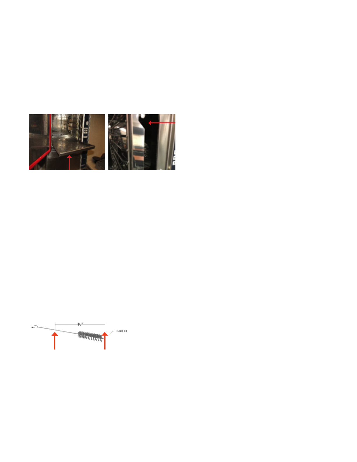
7. Clean cup and overow drains per instructions in “Cup & Overow Drains”
section.
8. Remove drain strainer and clean thoroughly to remove any build-up of debris.
9. Replace pan racks and steam lid. Steamer is now cleaned and ready to use.
DELIMING
The steamer control monitors the water level probes for cleanliness and to ensure
continuous steamer operation and reduce the need for service repair due to
probe cleaning issues. The control will display an advanced cleaning warning in
the event probe cleaning is required. Despite the warning, the steamer operation
will continue for a limited period of time of 8 hours and countdown clock will
be displayed. The countdown clock indicates how much time is available to the
operator to complete cooking process or regiment before the clock expires and
unit shutdowns automatically.
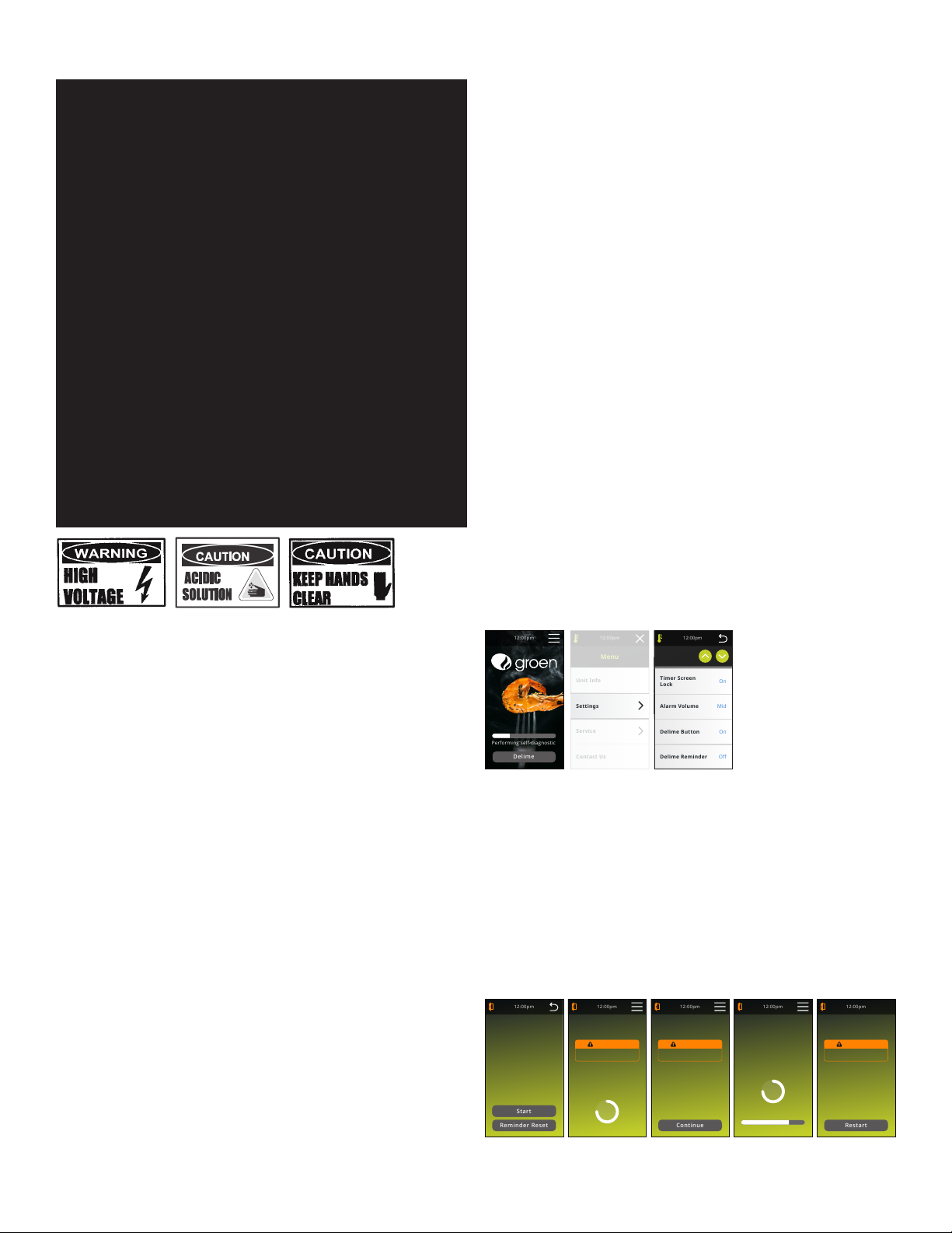
MM/DD/YY
Set Date
English
Language
°F
Temp
Indication
On
3
Number
of Timers
On
Compensating
Timers
On
Timer Screen
Lock
Off
12:00pm
Settings
2 min
Door Alarm
4
Brightness
Mid
Alarm Volume
On
Delime Button
Delime Reminder
Keyboard Beep
HH:MM
Set Clock
12 hr
Time Format
Contact Us
Service
Settings
Unit Info
12:00pm
Menu
Contact Us
Service
Settings
Unit Info
12:00pm
Menu
MM/DD/YY
Set Date
English
Language
°F
Temp
Indication
On
3
Number
of Timers
On
Compensating
Timers
On
Timer Screen
Lock
Off
12:00pm
Settings
2 min
Door Alarm
4
Brightness
Mid
Alarm Volume
On
Delime Button
Delime Reminder
Keyboard Beep
HH:MM
Set Clock
12 hr
Time Format
12:00pm
Performing self-diagnostic
Delime
DELIME button is only displayed during startup if the DELIME button is turned to
ON in settings menu. The default setting for DELIME button is OFF. The DELIME
REMINDER will provide you status visuals of where you are in the deliming
schedule. When the reminder is ON, the DELIME button will do the following:
•When 75% of the delime schedule has been reached, the DELIME button will
turn yellow
•When 90% of the delime schedule has been reached, the DELIME button will
turn yellow
•Upon expiration of the DELIME schedule, the DELIME button will turn red
•the DELIME button will return to normal after deliming has been completed or
the reminder is reset
12:00pm
Delime
Prepare Cavity
Remove Fan Shroud, Racks
and Steam lid. Please wait
a few minutes to allow
reservoir to fill with water.
WARNING
Hot Surfaces. Exercise caution
when removing hot components.
12:00pm
Delime
In Progress
Delime process has
begun. Process will take
approximately 60-90
minutes to complete.
Continue
12:00pm
Delime
Add Solution
Using caution, add specified
amount of approved
Deliming Solution into
water reservoir. Close door
and press continue.
WARNING
Hot Surfaces. Exercise caution when
touching interior compartment.
Restart
12:00pm
Delime
Complete
Allow unit to cool prior to
wiping out interior. Clean all
probes, steam lid, drip cup
and overflow drains. Replace
interior components. Press
restart to use the steamer or
push the Power Button to
turn off the unit.
WARNING
Hot Surfaces. Exercise caution when
touching interior compartment.
Start
Reminder Reset
12:00pm
Delime
Process Note
Prior to starting the
Delime process, review the
Operator's manual for
detailed instructions and
warnings.

7 OM-GSSP-BL-E BOILERLESS STEAMER
Press DELIME and follow instruction displayed on the unit (shown above) for the
delime procedure. Delime process takes approximately 60-90 minutes. Once
complete the unit will restart and go through the start up diagnostic sequence.
CUP & OVERFLOW DRAINS
1. Turn your unit off and allow it to completely drain. Units will drain automatically
when the units are powered off. This is a 5 minute process.
2. Once the reservoir has completely drained (approximately 5 minutes), stand
to the hinged side of the door and slowly open the door, allowing all of the
steam to escape from the cavity. Allow the cavity to completely cool down
and conrm that the reservoir has completely emptied before cleaning the
overow drain.
3. Remove the steam lid (image below left) and fan cover assembly (image below
right), prior to cleaning the overow drain.
4. Insert the cleaning brush into the cup and overow drains located at the lower,
middle, and back right side of your steamer’s cavity (image below). As the
brush is pushed through the overow drain, it will bend to follow the shape
of the drain as it travels the length of the overow drain. Once you use the
cleaning brush for the rst time, the wire between the handle and the bristles
will retain a curved shape after the brush is removed from the overow drain.
The brush is designed to bend/curve in this fashion. There is no need to
straighten the wire between cleaning/usage.
5. With the cleaning brush, push and pull through the entire lengthy of the cup
and overow drains several times. The brush should be inserted at least ten
inches (10) into the cup and overow drains to pass through the entire length
of the drain piping. Repeat as necessary until the cup and overow drains is
clean. Ensure that the cup and overow drains works properly by pouring or
squirting water into the cup and overow drains and conrming that the water
is owing freely into the drain receptacle and not being blocked and backing
up into the steamer cavity.
If the cup and overow drains is clogged such that the cleaning brush will
not clear the blockage or if water cannot move through the cup and overow
drains into the drain receptacle without backing up into the steamer cavity,
then a service call needs to be made and all use of the steamer must be
discontinued until the service agent evaluates the issue and conrms that the
unit is ready for further operation.
6. Clean the steaming cavity per the cleaning instructions in your operators’
manual.
7. Re-install the steam lid and fan cover assembly.
8. Leave the door open to prolong the life of the door gasket and to allow the
cavity to air out.
9. Clean, dry and store the overow cleaning brush after each use.
10. If a replacement brush is needed, the part number is 175977.
MAINTENANCE
The Boilerless Steamer is designed for minimum maintenance and no user
adjustments should be necessary. Certain parts may need replacement after
prolonged use. If there is a need for service, only Groen Authorized Service Agents
should perform the work.
If steam or condensate is seen leaking from around the door, take the following steps:
1. Check the door gasket. Replace it if it is cracked or split.
2. Inspect the steaming chamber drain to be sure it is not blocked.
3.
Adjust the door latch pin to allow for changes that might occur as the gasket ages.
a. Loosen the lock nut at the base of the latch pin, then turn the latch pin 1/4
turn clockwise, and tighten the lock nut.
b. After adjustment, run the unit to test for further steam leakage.
c. If there is still leakage, repeat the adjustment
d. Continue adjusting the pin clockwise until the door ts tightly enough to
prevent leakage. The hinge may also be adjusted.
REPLACEMENT PARTS
To order parts, contact your Authorized Service Agent. Supply the model
designation, serial number, part description, part number, quantity, and when
applicable, voltage and phase.
CONTACT US
If you have questions pertaining to the content in this manual, contact Unied

8 OM-GSSP-BL-E BOILERLESS STEAMER
WARRANTY
Congratulations on the purchase of your new Unied Brands equipment. We hope you
enjoy many years of reliable service in connection with the same. Please review all of
the important safety and operational information contained in the Operator’s Manual
for this equipment before it is placed in service. If you have any questions related to
equipment set up, operations, or service, please call 888-994-7636.
In addition, please review the sales terms and conditions set forth below.
*****IMPORTANT NOTICE*****
WARRANTIES, LIMITATIONS ON WARRANTIES, AND LIMITATION OF REMEDIES
The following Warranties, Limitation on Warranties, and Limitation of Remedies are
included in the terms of sale for this product. Please read this entire warranty and all
warranty modications, disclaimers, and limitations of remedies set forth herein before
accepting or using this equipment or product. Customer acknowledges and accepts
the provisions of this notice by Customer’s acceptance and use of the product. If these
provisions are not acceptable and agreed to by Customer, then please return this
product in its unused condition to Unied Brands or a Unied Brands authorized dealer.
UNIFIED BRANDS warrants this product against defects in material and workmanship
under normal use and services for which this product was designed. This warranty
runs only to the original end user and is in lieu of any other liability for defects.
THE WARRANTIES EXPRESSED IN THESE TERMS AND CONDITIONS ARE IN PLACE
OF ANY AND ALL OTHER EXPRESS WARRANTIES (UNLESS SEPARATELY STATED IN
PRINTED MATERIAL PREPARED BY US DESCRIBING OUR EQUIPMENT) AND EXCLUDE
ALL IMPLIED WARRANTIES, INCLUDING, BUT NOT LIMITED TO, ANY WARRANTY OF
MERCHANTABILITY OR FITNESS FOR ANY PARTICULAR PURPOSE; NOR ARE THERE
ANY OTHER WARRANTIES, EXPRESS OR IMPLIED, BY OPERATION OF LAW OR
OTHERWISE. In no event shall UNIFIED BRANDS be liable for damages or delay or
for any consequential, special or contingent damages arising out of any breach of
our warranty, whether or not we have knowledge of specic needs or our employees
or agents have given any specic assurances. Anyone claiming that there has been
a breach of warranty by UNIFIED BRANDS must give us written notice within THIRTY
(30) days after discovery of the relevant defect or the right to assert such claim will
have been waived conclusively and provided further that any such claim must also be
asserted within the general warranty period for such equipment and/or parts.
UNIFIED BRANDS will not be liable for any expense incurred without our prior written
authorization for alterations made outside of our factory or for repairs which are
not performed by UNIFIED BRANDS authorized service departments using UNIFIED
BRANDS factory parts. Nor shall we be responsible for the performance of equipment
as to which any repairs, revisions or alterations have been made by others.
THE EXCLUSIVE REMEDY OF THE USER OR BUYER AND THE EXCLUSIVE LIABILITY OF
UNIFIED BRANDS OR ANY SELLER OF UNIFIED BRANDS PRODUCTS, FOR ANY AND ALL
CLAIMS, LOSSES, INJURIES, OR DAMAGES (INCLUDING CLAIMS BASED ON BREACH
OF WARRANTY, CONTRACT, NEGLIGENCE, TORT, STRICT LIABILITY, OR OTHERWISE)
RESULTING FROM OR ARISING OUT OF THE USE OF HANDLING OF THIS PRODUCT,
SHALL BE THE RETURN OF THE PURCHASE PRICE OR AN AMOUNT NOT TO EXCEED
THE ORIGINAL PURCHASE PRICE OF THE PRODUCT OR, AT THE ELECTION OF UNIFIED
BRANDS OR THE SELLER, THE REPLACEMENT OF THE PRODUCT.
https://unifiedbrands.net/
Groen-Warranty-Information

9 OM-GSSP-BL-E BOILERLESS STEAMER
Service Log
Model No: Purchased From:
Serial No: Location:
Date Purchased: Date Installed:
Purchase Order No: For Service Call:
Date Maintenance Performed Performed By
This manual suits for next models
4
Table of contents
Other Groen Kitchen Appliance manuals

Groen
Groen HYPERSTEAM HY-6E User manual

Groen
Groen SSB-3G User manual

Groen
Groen Groen Tri-Res20 User manual

Groen
Groen SSB-3G User manual

Groen
Groen HFP/2E User manual

Groen
Groen SmartSteam OM-SSB-3E User manual

Groen
Groen HY-6CAV User manual

Groen
Groen SSB-3E User manual

Groen
Groen SSB-10EF Manual

Groen
Groen HY-24GF User manual

Groen
Groen AH/1 User manual

Groen
Groen HY-12 User manual

Groen
Groen Vortex VRC-3E User manual

Groen
Groen OM-BTD User manual

Groen
Groen HY-3E User manual

Groen
Groen SSB-10EF User manual

Groen
Groen Eclipse BPM-40G User manual

Groen
Groen Eclipse BPM-30E User manual

Groen
Groen SMARTSTEAM PRO User manual

Groen
Groen HY-12E User manual