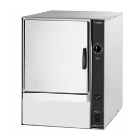
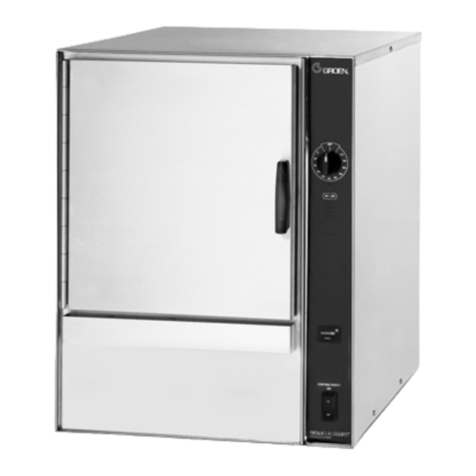
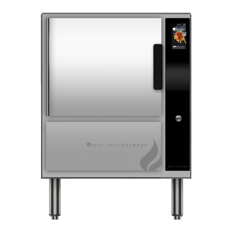
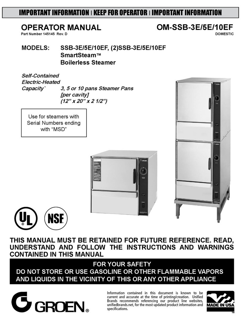
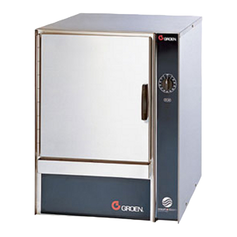
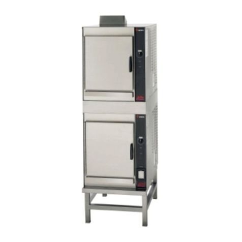
Groen SMARTSTEAM PRO User manual

SERVICE MANUAL
IMPORTANT INFORMATION, KEEP FOR OPERATOR
THIS MANUAL MUST BE RETAINED FOR FUTURE REFERENCE. READ,
UNDERSTAND AND FOLLOW THE INSTRUCTIONS AND WARNINGS
CONTAINED IN THIS MANUAL.
FOR YOUR SAFETY Do not store or use gasoline or other ammable
vapors and liquids in the vicinity of this or any other appliance.
WARNING Improper installation, adjustment, alteration, service or
maintenance can cause property damage, injury or death. Read the
installation,operating and maintenance instructions thoroughly before
installing or servicing this equipment.
NOTIFY CARRIER OF DAMAGE AT ONCE It is the responsibility of the
consigneetoinspectthecontaineruponreceiptofsameandtodetermine
the possibility of any damage, including concealed damage. Unied
Brandssuggeststhat if youaresuspicious of damagetomake a notation
onthedeliveryreceipt.It will bethe responsibility oftheconsignee to le
a claim with the carrier.We recommend that you do so at once.
Manufacture Service/Questions 888-994-7636.
PART NUMBER 179214, REV. A (06/22)
This manual provides information for:
SMARTSTEAM® PRO
BOILERLESS STEAMER,DOMESTIC
GSSP-BL-3E/3ES/5E/5ES/10ES &
(2)GSSP-BL-3ES/5ES/10ES
GSSP-BL-3G/3GS/5G/5GS/10GS &
(2)GSSP-BL-3GS/5GS/10GS
888-994-7636, fax 888-864-7636
uniedbrands.net
The information in this document is Condential and shall not be disclosed to any third party without the express written
consent of Unied Brands. Information contained in this document is known to be current and accurate at the time of printing/
creation. Unied Brands recommends referencing our product line websites, uniedbrands.net, for the most updated product
information and specications. © 2022 Unied Brands. All Rights Reserved.
TABLE OF CONTENTS
Introduction... 2
Groen Certied Service... 2
Warranty & Non-Warranty Repair... 2
Safety... 2
Glossary of Terms... 2
Tools & Supplies... 2
How to Use this Manual... 3
Operation... 3
Controls... 3
Operating Procedure... 4
Typical Questions... 4
Installing,Cleaning & Testing... 5
Electric Model Installation... 5
Gas Model Installation... 6
Installation... 6
General Cleaning... 7
Heavy User Deliming Maintenance Program... 8
Element Wiring... 8
Troubleshooting... 10
Diagnostics... 10
Error Codes... 11
Amperage/Resistance Chart... 12
Gas Orice Size Chart... 12
Wiring Diagrams & Schematics... 13
Assembly / Disassembly... 23
General Information... 23
Cavity Compartment Side Panels... 23
Top Cover... 23
Steamer Display Control... 23
I/O Board... 23
Steam Reservoir Drain Valve... 23
Door Removal/Installation/Alignment... 23
Door Reversal Procedures... 24
Door Switch... 24
Door Gasket... 24
Probe... 24
Element... 25
Burner... 25
Service Bulletin # 194... 25
Parts List... 26
Graphic User Interface... 49
General Notes... 49
Initial Startup... 49
Manual Cook... 50
Home... 51
Timed Cook... 52
Hold Mode... 53
Pan Timers... 53
Menu... 54
Settings... 55
Service... 56
Delime... 59
Errors... 61
Shutdown... 62
All Menus... 63

2 SM-GSSP BOILERLESS STEAMER
INTRODUCTION
Since 1907 Groen has been in the business of designing and manufacturing the
nest commercial appliances for the food service industry. Chefs, cooks and
kitchen support personnel have come to depend upon the quality of construction
and the reliability of operation.
Groen, in turn, depends upon our service centers and their eld service personnel
to keep the equipment in top operation condition. In order to do this, our designs
are made with service and reliability in mind.
Once the Groen equipment is sold, manufactured, delivered and installed, our
reputation is clearly in your hands. As part of our team, we value your efforts and
input to our production design.
We will do all we can to make your job of keeping the equipment in perfect
working order as easy as we can. Together, we will keep our customers satised.
GROEN CERTIFIED SERVICE
The SmartSteam Pro Boilerless Steamer has been carefully designed to provide
many years of efcient and reliable service. Part of the quality program is Groen
Certied Service. This includes:
• Groen certies that all equipment delivered to our customers has been
inspected and tested for compliance with the specications.
• Groen certies that all parts required for service and maintenance will be
readily available.
• Groen certies that this manual will be updated by means of periodic service
bulletins to provide the most up-to-date information for eld maintenance
and service personnel.
WARRANTY & NON-WARRANTY REPAIR
Groen Warranty provisions are clearly presented in the customer’s Operator
Manual. Certain procedures for the cleaning and/or adjustment of the
SmartSteam Pro Boilerless Steamer are presented in this manual for reference,
but not warranty related.
SAFETY
The Groen SmartSteam Pro Boilerless has been designed with safety in mind.
This includes safety to the operating and maintenance personnel, safety to the
facility in which the equipment is installed and safety to the equipment itself.
The steamer has been designed to the highest industry standards and has
been certied by the National Sanitation Foundation Testing Laboratory (NSF),
Underwriters Laboratory (UL) and/or CSA (gas).
The steamer contains several devices which are specially used to prevent
unsafe conditions. If they are disconnected during service, make sure they are
reinstalled properly and tested before the steamer is operated.
The safety precautions in the manuals are in accordance with ANSI 535
Standard. Three different signal words alert you to a hazardous situation:
DANGER, WARNING, AND CAUTION.
DANGER: The signal word danger indicates that a hazardous situation exists and
could result in serious injury or death.
• Do not store or use gasoline or other ammable vapors and liquids in the
vicinity of this or any other appliance.
• When you open the steamer door, be very careful to avoid escaping steam.
Steam can cause burns.
• After removing the fan bafe partition, do not put your hands or other object
into the cooking cavity until the fan comes to a complete stop. Rotating fan
blades can cause severe injury!
WARNING: The signal word WARNING tells you that a possibly hazardous
situation is present, and if not avoided, could cause serious injury or death.
• Always turn off steamer power before removing partitions or panels.
• Disconnect the steamer from the power source before performing any
service.
• Unit has disconnect power switch located on the rear panel.
CAUTION: The signal word CAUTION warns you of a hazardous situation which,
if not avoided, may result in minor or moderate injury.
• Steamer may be hot. Take precaution to prevent any contact with hot
surfaces.
• Be sure all interior partitions have been installed before operating the
steamer.
• All steamer operators and service personnel should be familiar with correct
and safe operating procedures.
• Be sure steamer drain is not blocked as this could result in improper steamer
operations.
Two other signal words, not directly related to personal safety, are also used in
this manual: NOTICE and IMPORTANT
NOTICE:Notice is used to alert you to hazards that may result in component and/
or equipment damage.
IMPORTANT: Important is used to highlight an operating or maintenance tip or
suggestion.
GLOSSARY OF TERMS
The following abbreviations and terms are used in this manual:
BTU British Thermal Unit
GPM Gallons per Minute
LED Lighting Emitting Diode
MM Millimeter
NEC National Electric Code
N.P.T. National Pipe Thread
NSF National Sanitation Foundation
PSI Pounds per Square Inch (Pressure)
U.L. Underwriter’s Laboratory, Inc.
TOOLS & SUPPLIES
CAUTION: CARE SHOULD BE TAKEN IN USING THE CORRECT TOOLS AS INDICATED.
USING THE WRONG TOOL MAY INFLICT DAMAGE TO THE PART BEING
REMOVED, INSTALLED AND/OR ADJUSTED. MAKE SURE THAT THE
CALIBRATIONS ON INSTRUMENTS ARE PERIODICALLY CHECKED FOR
ACCURACY.
This section identies the tools, instruments and supplies which will be required
and useful in the inspection, repair and testing of the equipment described in
this manual.
Most likely, many of these tools and supplies are already in your kits and are
used in everyday maintenance. Make sure to only use the specied sealants,
compounds and dressings recommended by Groen.
REQUIRED TOOLS
• Screw Drivers: Flat Blade No.1 and No. 2
• Phillips No.1 and No. 2
• Socket Wrenches: ¼” through 7/8”
• Nutdrivers (metric and inches)
• Open Ended Wrenches
• Pipe Wrenches: 6” and 8” size
• Allen Wrenches: 1/16” through ¼”
• Slip Joint pliers: Channel Lock or Equivalent
• Wire Crimpers

3 SM-GSSP BOILERLESS STEAMER
RECOMMENDED INSTRUMENTS
• Digital Multimeter: Fluke Model 77 or equivalent
HELPFUL HARDWARE
• Extension Mirror
• Screw Starter
• Level: 18” Model
• Fuse Puller
RECOMMENDED SUPPLIES
• Pipe Thread Compound: Brand: LACO Pipe Tite Stik No. 11176 or equivalent
• Motor Sealant Grease: Bel-ray
• 2” Aluminum Duct Tape
• Removable Thread Locker: Loctite Type 242 (Door), Loctite Type 222
(Exterior)
• Clear Silicone Sealant: Dow Corning Type 732
• Silicone Heat Sink Compound: Non-Fluid Oil Corp., Chemplex 1381
• High Temperature Anti-Seize and Lubricating Compound: Bostix NEVER
SEEZ NSBT-16
HOW TO USE THIS MANUAL
Read this manual completely before attempting any disassembly or repairs.
Please note the similarities and differences between the various models
described in the manual.
Before making repairs, you should have knowledge of the steamer operation as
described in the Operations Section of this manual and a good understanding of
service techniques as presented by the Groen Service School.
This service manual should be taken with you on all service calls. Use the correct
tools in accordance with the procedures shown and use only Groen Certied
Replacement Parts when performing steamer repairs.
OPERATION
WARNING: ANY POTENTIAL USEROF THEEQUIPMENT MUSTBE TRAINEDIN SAFEAND
CORRECT OPERATIONG PROCEDURES.
WARNING: WHEN YOU OPEN THE DOOR,STAY AWAY FROM THE STEAM COMING OUT
OF THE UNIT.THE STEAM CAN CAUSE BURNS.
WARNING
AVOID STEAM CONTACT
CONTROLS
Touchscreen Graphic Display
ON/OFF Push Button
Operator controls are on the front right of the unit.
The Groen SmartSteam Pro Boilerless control panel has the touchscreen graphic
display and the ON/OFF push button.
The touchscreen graphic display allows the user to enter and exist the three
cook modes (MANUAL, TIMED and HOLD) and select various settings with
different menus with the controls. The display also provide several audio and/or
visual indicators to the user as cleaning reminders, when the unit reached ready
temperature, hours of operation, error codes, etc.
The ON/OFF button get the Groen SmartSteam Pro Boilerless ready for use or
shuts it off.
COOK MODE OPERATIONS
1. At the home screen or idle mode, the steam generator stay at a low boil or
ready temperature.
2. When the TIMED button is pushed, time can be set by entering the time in
the HH:MM format. The unit steams until the timer counts down to zero and
goes into HOLD mode while timer counts up. At that time the STOP light
illuminates and a beeper sounds.
3. When the MANUAL button is pushed, the unit steams continuously.
4. HOLD mode the steam generator maintains a warming temperature below
the ready temperature.

4 SM-GSSP BOILERLESS STEAMER
When the MANUAL button is pushed, the heat remains on continuously and
produces full steam.
When the TIMED button is pushed, the display allows time to be entered in hours
and minutes, the heater turns on producing full steam, and the timer counts
down to zero automatically switching to HOLD with audible alert and timer
begins to count up. Heaters will cycle on and off to maintain cavity temperature
between 160º and 170ºF. At any time while in TIMED & HOLD mode, the “+1m”
button will add one minute of cook timer or transition HOLD to TIMED mode for
one minute turning heaters on producing full production.
When the door is open the display shows the door open icon. If “Compensating
Timer” set to “On”, the timer stops counting down, and the heater stops heating.
Close the door to resume timing and heating. If “Compensating Timer” is set
to “Off”, then timer will continue to count down even if door opens and closes.
When the timer counts down to zero the display shows three dashes, the beeper
sounds, and the heater cycles on and off slowly to keep the water temperature
just above the ready temperature. Push the CANCEL button to stop the beeper.
The “X” button may be pushed at any time to stop the MANUAL or TIMES modes.
If the door is open during the cooking process, the door interlock switch causes
power to be removed from the convection motor. The relay or gas valve opens
the circuit of the source of heat, instantly reducing the heat from the steam
reservoir.
WATER ENTRY INTO STEAM RESERVOIR
CAUTION: A SCALED RESERVOIR OR DEBRIS WILL CAUSE ERROR CODES. WHEN A
PROBE HAS EXCESSIVE SCALE IT WILL NOT FUNCTION PROPERLY.
NOTICE: WHEN POWERED OFF,THE CONTROLS EMPTY THE STEAM RESERVOIR.
On power up, the boiler goes through a ll/drain diagnostic to verify the condition
of the water level probes and drain. If either probe is not responding, a error code
is generated.
The LOW WATER probe determines if there is a full and proper level of water in
the steam reservoir. If the water level goes down, he probe is open by the water
level getting low. This causes the water ll valve for that steam reservoir to turn
on to permit water to enter the steam reservoir.
Water will continue to enter the steam reservoir until the level of water is high
enough to close the LOW WATER probe. This determines that the steam reservoir
is full and the water supply solenoid valve is turned off stopping the water ow
to the stem reservoir.
When the LOW WATER probe is open, there is a 3 second delay before the water
ll valve opens. This is to take into account the rising and lowering of the water
level due to the bubbling action of the boiling water in the steam reservoir. If the
probe is open for more than approximately 3 seconds, then the water ll valve
is activated.
SERVICE CODES
Error codes are normally cause by probes or timing issues (ll time and drain
time).
A error code is generated when the electronic controls are blind to the status
of the steam reservoir (i.e., probes are not working) or by a blocked drain. The
error may stop the machine from running and the error code number will be
displayed as a pop-up message on the touchscreen. Error codes protect the
steam reservoir from irreparable damage.
HEATER CONTROL
NOTICE: IF THEDOOR ISOPEN,THE HEATING CIRCUIT WILLNOTBE ENERGIZEDAND
THE HEATING CIRCUIT WILL NOT TURN ON UNTIL THE DOOR IS CLOSED.
After the reservoir is initially lled and the diagnostic is complete, the relay
(electric) or gas valve (gas) energizes providing power to the heating circuit.
Then the control monitors the Ready Thermostat and determines when the
cavity is in “ready” condition.
If the Ready thermostat is at the required temperature and the Home screen
displayed (no cooking mode selected), the heater control cycles the heating
OPERATING PROCEDURE
1. Press the ON/OFF push button. The screen will display a self-diagnostic
screen with progress bar. The drain will close and the steam generating
reservoir will begin lling. When the low probe closes, drain will open until
low probe is open. The drain will close and the steam generating reservoir
lls to high probe until it closes, then the drain will open and the reservoir
drains until high probe is open, then heat will turn on if door is closed.
Unit will continue to drain until low probe opens, then drain will close and
reservoir will ll until the low probe closes. Fill sequence in complete and
the display screen will transition to MANUAL mode and preheating continues
until READY icon turns on (about 10-15).
2. Load food into pans in uniform layers. Pans should be lled to about the
same levels, and should not be mounted.
3. Open the door and slide the pans on to the supports. If you will only be
steaming one pan, put it in the middle position. Some foods will cause foam.
When cooking foods that foam, such as shrimp, put an empty solid 2 ½’
deep pan in the bottom slot of the pan racks.
4. Close the door. When the READY indicator is lit, take one of the following
steps:
• If you want to steam the food for a certain length of time, push the
TIMED button and set the desired time with the TIMER knob. The timer
will automatically run the steamer for the set time and then go into
HOLD. A beeper will sound. Then push “X” button to stop cancel “HOLD”.
• If you want to steam continuously, push MANUAL button. The unit will
continue steaming until stopped.
• Push “X” to stop producing steam.
5. To remove pans from cavity, open the door. Remove the pans from the
steamer, using hot pads or oven mitts to protect your hands from the hot
pans.
6. To shut off the unit, press the ON/OFF push button. The screen will display
a shutdown screen with progress bar. The steam generating reservoir will
begin lling to the high probe until it closes and then drains until the low
probe opens and rells.
NOTE: If a large amount of shrimp is cooked in the steamer, foaming will occur
because the steam lid actually gets so hot that the shrimp will cook on its
surface and the shrimp proteins in the dripping will foam on the surface of the
steam lid. *To avoid this, use a catch pan to catch shrimp drippings and proteins
to prevent foaming when cooking a large amount of shrimp.
TYPICAL QUESTIONS
The following is a sequence of events typical to SmartSteam Pro Boilerless
Steamers.
COOKING FOOD
To use the steamer, ensure the cavity door is closed, press the ON/OFF push
button to on (button light illuminates). The unit veries the probes and drain
using the following sequence. The drain valve is closed and the water enters the
seam reservoir to the “ll” point. When the water level reaches the LOW level
probe, the water ll valve closes and the drain valve opens until water drops off
the LOW probe. At this point, the drain valve closes and the water valve opens to
rell to the HIGH probe. Drain valve opens allowing water to drop off HIGH probe
and the heater will operate. Water level will continue to drop off the LOW probe.
Drain valve closes and water opens and rells until water reaches LOW probe,
then water ll closes, stopping the entry of water into the steam reservoir.
A relay (electric) or gas valve (gas) energizes and provides power to the heating
circuit for the steam reservoir. This heats the steam reservoir to boil the water-
creating the required steam. When the cavity is heated above 180ºF, the READY
icon comes on with an audible alert indicating that the cooking can start. When
it is desired to cook food in the cavity, the pans are inserted into the cavity and
the door is closed.
Steamer starts in MANUAL mode and heat-up time is about 15 minutes after the
steamer is switched on, if all above conditions are met.
5 SM-GSSP BOILERLESS STEAMER
circuit power relay or gas valve and maintains the ready conditions by cycling
the elements 18 seconds ON, 6 minutes OFF.
If the MANUAL mode is on, the heater control continuously turns on heat to
produce steam.
If HOLD mode is on, the HOLD and READY thermostats operate the control the
heat on the following conditions:
Scenario #1
1. When “HOLD” button is pressed, if HOLD and READY thermostats are
closed then heat will turn on.
2. Heat will remain on until HOLD and READY thermostat opens.
3. When READY thermostat opens, heat turns off.
4. Heat will remain off until READY thermostat closes then heat ON/OFF
cycle rate will initiate.
5. Heat cycle will continue until HOLD “X” is pressed to exit or the unit is
turned off.
6. If the HOLD thermostat closes due to drop in temperature, and the
READY thermostat is still closed, then the heat turns on and sequence
returns to step 2.
Scenario #2
1. When “HOLD” button is pressed, if HOLD thermostat is open and READY
thermostat is closed then heat will turn on.
2. Heat will remain on until READY thermostat opens.
3. When READY thermostat opens, heat turns off.
4. Heat will remain off until READY thermostat closes then heat ON/OFF
cycle rate will initiate.
5. Heat cycle will continue until HOLD “X” is pressed to exit or the unit is
turned off.
6. If the HOLD thermostat closes due to drop in temperature, and the
READY thermostat is still closed, then the heat turns on and sequence
returns to step 2.
Scenario #3
1. When “HOLD” button is pressed or “Timed Cook” mode expires, if HOLD
and READY thermostats are open, then heat will turn off.
2. Heat will remain off until READY thermostat closes.
3. Heat will remain off until READY thermostat closes then heat ON/OFF
cycle rate will initiate.
4. Heat cycle will continue until HOLD “X” is pressed to exit or the unit is
turned off.
5. If the HOLD thermostat closes due to drop in temperature, and the
READY thermostat is still closed, then the heat turns on and sequence
returns to step 2.
A High-Limit thermostat is provided as a safety device on each steam reservoir
to monitor the internal temperature of the steam reservoir. This temperature is
set for 280ºF and will shut down the steamer if there is very little or no water and
the steamer cavity starts to overheat.
DRAINING WATER FROM THE STEAM RESERVOIR
When water or steam is drained from the reservoir, it passes through a water
spray in the drain box controlled by a water solenoid valve to condense the
steam before it exits the steamer drain box into the drain line.
A solenoid drain valve is connected to each steam reservoir. This valve is
normally open, permitting water from the steam reservoir to drain out. When the
unit is turned on, the steam generator drain valve closes and the steam reservoir
starts to ll/drain, and the sequence runs until water reaches the proper level
for cooking operation.
When the unit is turned off, the solenoid valve opens and drains the water from
the steam reservoir. When water is drained from the steam reservoir, it passes
through the drain box and then into the drain line.
When the unit is turned off by the ON/OFF push button, the steamer will ll to the
high probe, drain, rell and drain. This is to remove the heat from the reservoir
for cleaning and reduce any possible cavity warping.
*If hot water is existing, the drain fan thermal switch could close and energize
circuit giving error code 19.
LOW WATER LEVEL DETECTION
Because prolonged operation with less than the required amount of water in the
steam reservoir could present a dangerous situation, the control takes action to
prevent the situation.
If the low probe is satised, the heat turns on and continues operation. If the low
probe is not satised, the control begins to operate unit on the HIGH water level
probe for a period up to a 8 hours maximum.
INSTALLING,CLEANING & TESTING
WARNING: THE UNIT MUST BE INSTALLED BY PERSONNEL WHO ARE QUALIFIED TO
WORK WITH GAS,ELECTRICITY AND PLUMBING. IMPROPER INSTALLATION
CAN CAUSE INJURY TO PERSONNEL AND/OR DAMAGE TO THE QUIPMENT.
THEUNITMUST BEINSTALLEDINACCORDANCEWITHAPPLICABLECODES.
CAUTION: DO NOT INSTALL THE UNIT WITH THE REAR VENTS BLOCKED,OR WITHIN 2
INCHES OF A HEAT SOURCE SUCH AS A BRAISING PAN, DEEP FAT FRYER,
CHARBROILER OR KETTLE. TO AVOID DRAINAGE PROBLEMS, LEVEL THE
UNIT FRONT TO BACK,AND PITCH IT SLIGHTLY TO THE FRONT.
WARNING: TO AVOID DAMAGE OR PERSONAL INJURY, FOLLOW THE WIRING DIAGRAM
EXACTLY WHEN CONNECTING THE UNIT.
CAUTION: EACHUNIT MUST HAVEA SEPARATEGROUNDWIRE FOR SAFE OPERATION.
ELECTRIC MODEL INSTALLATION
ELECTRICAL SUPPLY CONNECTION
1. Panel Removal – Right Side: Open the wiring and control panel by removing
screws from the right side panel. Slide the panel forward and set it aside.
2. Supply Voltage: The unit must be operated at the rated name plate voltage.
The name plate can be found on the right side panel.
3. Phase Selection: Refer to steamer wiring diagram (pages 15-16) and
element wiring (pages 8-10).
4. Terminal Block: The terminal block for incoming power is located at the back
of the control compartment, the ground terminal is located in the wiring
compartment near the terminal block.
5. Supply Wire: The equipment grounding wire must comply with the National
Electrical Code (NEC) requirements. The wiring diagram on the inside of
the unit’s right side cover gives directions for the proper connection of the
terminal block to the supply power. The proper wire must be used or the unit
will not meet Underwriters Laboratories and NEC requirements. The electric
hole is sized for a 1” conduit tting on the GSSP-BL-3E and GSSP-BL-5E.
The electric hole is sized for a 1-1/4” conduit tting on the GSSP-BL-10E.
6. Branch Circuit Protection: Each SmartSteam Pro Boilerless Steamer,
including individual units of stacked models, should have its own branch
circuit protection and ground wire. Current and power demands for each
unit are as shown below.

6 SM-GSSP BOILERLESS STEAMER
AMPERAGE/RESISTANCE CHART
Model Voltage/Phase Amperage Resistance
GSSP-BL-3E 208 3-PHASE 25 8.3
GSSP-BL-3E 240 3-PHASE 22 10.9
GSSP-BL-3E 480 3-PHASE 11 43.6
GSSP-BL-3E 208 1-PHASE 44 4.7
GSSP-BL-3E 240 1-PHASE 38 6.3
GSSP-BL-5E 208 3-PHASE 34 6.1
GSSP-BL-5E 240 3-PHASE 29 8.3
GSSP-BL-5E 480 3-PHASE 15 32
GSSP-BL-5E 208 1-PHASE 58 3.6
GSSP-BL-5E 240 1-PHASE 50 4.8
GSSP-BL-10E 208 3-PHASE 59 3.5
GSSP-BL-10E 240 3-PHASE 51 4.7
GSSP-BL-10E 480 3-PHASE 26 18.5
GAS MODEL INSTALLATION
Although Groen recommends the SmartSteam Pro Boilerless Steamer is installed
near non-combustible surfaces, the following minimum clearances are to any
surface, combustible or non-combustible.
Right Side: 2 inches
Left Side: 2 inches
Rear: 6 inches
However, for easy service, at least 6 inch clearance should exist for right side
access to gas shut-off valve.
The unit must be installed in a well-ventilated room with an adequate air supply.
The steamer must be installed beneath a ventilation hood since gas combustion
products exit the appliance.
Any item which might obstruct the ow of air for combustion and ventilation
must be removed. Do not obstruct the ue cover or rear vents after installation.
The area directly around the appliance must be cleared of all combustible
material. The installation must conform with local codes or, in the absence of
local codes, with the National Fuel Gas Code, ANSI Z223.1/NFPA 54, or the
National Gas and Propane Installation Code, CAS B149.1.
The unit and its individual shutoff valve must be disconnected from the gas
supply system during any pressure testing of that system which has test
pressures in excess of ½ PSI (3.45kPa). It must be isolated from the gas supply
piping system by closing its individual manual shutoff valve during any pressure
testing of the gas piping system which has test pressures equal to or less than
½ PSI (3.45 kPa).
ELECTRICAL SUPPLY CONNECTION
Provide 115 VAC, 60 HZ, 1 PH, 15 AMP service. Bring wire in through hole on
the back panel. Each cavity requires a separate cord for connection. Local codes
and/or the National Electrical Code should be observed in accordance with ANSI/
NFPA 70. AN ELECTRICAL GROUND IS REQUIRED. The wiring diagram, located
in the service compartment and in this manual. Maximum load is 2-1/2 AMPS.
In Canada provide electrical service in accordance with the Canadian Electrical
Code, CSA C22.2 part 1 and/or local codes.
GAS SUPPLY CONNECTION
Connection to the gas supply shall be in accordance with the chart below. Supply
pressure must be at least 4.5” W.C. (maximum 14” W.C.) for natural gas or 12”
W.C. (maximum 14” W.C.) for LP gas. In Canada, the installation must conform
to the Canadian Gas Code, CAN 1-B149. Installation Codes for Gas Burning
Appliances and Equipment and/or local codes. Check all gas connections for
leaks prior to unit operation.
RATINGS FOR GAS CHART
Model BTU OPERATING
PRESSURE INCOMING GAS FEED RATE
MIN MAX
3G Natural 54,000 4.30” WC 5”WC 14” WC
3G Propane 54,000 10.5” WC 12” WC 14” WC
5G Natural 58,000 4.30” WC 5”WC 14” WC
5G Propane 58,000 10.5” WC 12” WC 14” WC
10G Natural 100,000 4.30” WC 5”WC 14” WC
10G Propane 100,000 10.5” WC 12” WC 14” WC
INSTALLATION
NOTICE: THE QUALITY OF THE WATER IS A FACTOR IN THE PROPER PERFORMANCE
OF THE STEAMER. THE WATER SUPPLY SHOULD HAVE A MINIMUM VALUE
OF 30-40 PARTS PER MILLION OF TOTAL DISSOLVED SOLID (TDS).
Many of the problems associated with the degraded performance or non-
operation of the SmartSteam Pro Boilerless Steamer can be traced directly to
improper installation and/or lack of proper and periodic cleaning-all of which is
the responsibility of the customer.
This section is provided to determine that the equipment was installed correctly,
to indicate the proper cleaning techniques ads to be used by Groen customers
and steamer test procedures.
It is to be expressly noted that ALL work associated with the installation and
cleaning of the SmartSteam Pro Boilerless Steamer is NOT covered by the Groen
warranty provisions.
WATER CONNECTION
Make sure that the incoming water connection is made with a ¾” N.H. COLD
water supply hose. Rigid pipe is not required. The water pressure should be
between 30 and 60 PSIG. Higher pressures will require the use of a pressure
regulator. Make sure that all connections are tight with no leaks-no matter how
small.
LEVEL INSTALLATION
It is preferable that the steamer be installed level side to side (left to right) and
slightly pitched (1 to 5 degrees) back to front, with the front always being lower
that the rear. This allows the condensate water to go to the drain at the front of
each cavity.
Make sure that all leg extensions are tight against the oor and that the steamer
is supported on all four legs.
DRAIN LINE INSTALLATION
The drain line should not be less than 1-1/2” – for single units, 2” (5E) – for
double stacked units.
There must be a 2” air gap to the (non-pressurized) building drain. Make sure
that the drain is sloped AWAY and DOWN from the steamer and that there are
no obstructions in the line. Failure to observe these requirements may cause a
water trap in the drain line and produce enough back pressure to prevent proper
cavity draining –resulting in condensate water leaking from the door. Drain line
must NOT be made of plastic pipe. It must be able to withstand boiling water.

7 SM-GSSP BOILERLESS STEAMER
Do not install rear of unit within 24” radius from the drain outlet to any steam
producing device. Do not install steamer directly above steam venting oor
drains.
If the oor drain “only” services this steamer, then the drain may be located
within the steam-free zone. The steam-free zone must be covered if other
appliances cause steam at the oor drain.
INSTALLATION CHECKLIST
General
Refer to Installation on page 6
Do not install steamer directly above steam venting oor drain
Make sure the unit rear vents are not blocked and the unit is not within 2” of
a heat source
Make sure the steamer is level or pitched slightly forward
Check that fan is clean and clear of foreign materials
Gas Connection Checks
Make sure installation conforms to local codes
Make sure steamer is installed under a ventilation hood. Check that the ue
and all vents are free of obstruction
Check that gas supply is 5” W.C. (min) to 14” W.C. (max) for natural gas, and
12” “W.C. (min) to 14” W.C. (max) for propane
Check that gas supply piping is ½” NPT
Verify operating gas pressure per chart on page 6
Electrical Checks
Make sure the steamer is properly grounded
Verify that the electrical connections conform to all local codes and the NEC
requirements
Make sure the power supply branch circuit conforms to the specications
indicated on the steamer nameplate
Steamer Door Check
Make sure the door gasket is making good contact with the cavity frame
Instruct operators to leave the door open when the steamer is shut down
overnight or longer
Cold Water Supply Connections
Make sure plumbing connections conform to local codes
If permitted by local codes, check that hose connection is exible to allow
steamer movement for servicing
Check inlet water pressure is 30-60 PSIG
Check that the water feed line is a minimum on ½” inside diameter
Check water ow per Installation on page 6
Drain Connections
Make sure drain plumbing connections comply with local codes
Make sure drain line is 1- 1/12” and 2- 1/2” on stacked units
Check that drain line is suitable for boiling water. Make sure PVC is not being
used for drain plumbing
Check that drain line is pitched downward
Make sure drain line is free of obstruction
Make sure drain is not connected to a building drain
GENERAL CLEANING
WARNING: DISCONNECTTHEPOWERSUPPLYBEFORECLEANING THEOUTSIDE OFTHE
STEAMER. KEEP WATER AND CLEANING SOLUTIONS OUT OF CONTROLS
ANDELEVTRICALCOMPONENTS.NEVERHOSEORSTEAMCLEANANYPART
OF THE UNIT.
AVOID CONTACT WITH ANY CLEANSER, DELIMING AGENT OR DEGREASER
AS RECOMMENDED BY THE SUPPLIER. MANY ARE HARMFUL. READ THE
WARNINGS AND FOLLOW THE DIRECTIONS.
EVEN WHEN THE UNIT HAS BEEN SHUT OFF,DON’T PUT HANDS OR TOOLS
INTO THE COOKING CHAMBER UNTIL THE FAN HAS STOPPED TURNING.
DON’T OPERATE THE UNIT UNLESS THE REMOVABLE PARTITION HAS BEEN
PUT BACK IN ITS PROPER LOCATION.
DONOTUSEANYCLEANINGAGENTTHATCONTAINSANYSULFAMICAGENT
OR ANY CHLORIDE,INCLUDING HYDROCHLORIC ACID (HCI). TO CHECK FOR
CHLORIDE CONTENT,SEE ANY MATERIAL SAFETY DATA SHEETS PROVIDED
BY THE CLEANING AGENT MANUFACTURER.
WARNING: DO NOT DISASSEMBLE PROBES DURING CLEANING AS BREAKAGE WILL
RESULT. USE HOT WATER TO WASH OUT PIVOT JOINTS OF PROBE.
To keep your SmartSteam Pro Boilerless Steamer in proper working condition, us
the following procedure to clean this unit. This regular cleaning will reduce the
effort required to clean the steam reservoir and cavity.
SUGGESTED TOOLS
• Mild detergent or vinegar
• Stainless steel exterior cleaner such as Zepper
• Cloth of sponge
• Spray bottle
• Nylon pad
• Towels
• Plastic disposable gloves
PROCEDURE EXTERIOR CLEANING
1. Prepare a warm solution of the mild detergent as instructed by the supplier.
Wet a cloth with this solution and wring it out. Use the moist cloth to clean
the outside of the unit. Use the moist cloth to clean the outside of the unit.
Do not allow freely running liquid to touch the controls, the control panel, any
electrical part, or on the side or rear panels.
2. To remove material which may be struck to the unit use a ber brush, or a
plastic or rubber scraper with a detergent solution.
3. Stainless steel surfaces may be polished with a recognized stainless steel
cleaner such as “Zepper”.
PROCEDURE INTERIOR CLEANING
Clean the unit daily or as residue builds upon the bottom of the oven cavity.
1. Press OFF push button to turn the steamer off. Open the door.
2. Allow unit to shutdown, drain the water and allow the unit to cool before
cleaning.
3. After the unit has cooled, remove steam lid, pan racks, and drain guard from
the cavity.
4. Use a mild detergent to wipe down the steamer cavity and the probes on
the right side wall. Clean steam lid, pan racks and drain guard. Use brush
provided to clean out condensate and overow drains.
5. Rinse the unit to remove detergent.
6. Reinstall drain guard, pan racks and steam lid. Unit is ready for use.

8 SM-GSSP BOILERLESS STEAMER
HEAVY USER DELIMING MAINTENANCE PROGRAM
WARNING: FOLLOW THE HANDLING INSTRUCTIONS PROVIDED WITH THE DELIMER/
DESCALER, INCLUDING THE RECOMMENDATIONS FOR THE PROTECTIVE
RUBBER GLOVES, PROTECTIVE CLOTHING/BOOTS AND PROTECTIVE
EYEWEAR.
IMPORTANT:DONOTUSEANYMETALMATERIAL(SUCHASMETALSPONGES)ORMETAL
IMPLEMENTS (SUCH AS A SPOON, SCRAPER, OR WIRE BRUSH) THAT
MIGHT SCRATCH ANY STAINLESS STEEL SURFACE.SCRATCHES MAKE THE
SURFACEHARDTO CLEANANDPROVIDEPLACESFORBACTERIATOGROW.
DO NOT USE STEEL WOOL, WHICH MAY LEAVE PARTICLES IMBEDDED IN
THE SURFACE WHICH COULD EVENTUALLY CAUSE CORROSION AND
PITTING.
WARNING: ALLOW THE STEAMER TO COOL COMPLETELY BEFORE DELIMING. HOT
SURFACES CAN CAUSE SEVERE BURNS.
PURPOSE
SmartSteam Pro Boilerless Steamers are designed to require only a daily
cleaning of the steamer cavity, pan racks, steam lid and probes to maintain
full performance. Daily cleaning may not be sufcient to control scale build-up,
when a boilerless steamer is operated in a heavy duty, continuous operation in
an area with extreme hard water.
The following procedure outlines steps for optional periodic deliming for
steamers in heavy duty applications and extreme water conditions. The
frequency of the deliming depends upon the severity of the scale build-up and
individual operators.
RECOMMENDED TOOLS & CLEANERS
• Nylon scrub pad, cloth or sponge: Scotch-Brite™ medium duty scrubbing
sponges are preferred. DO NOT use metal scrub pads.
• Delimer/Descaler: Groen Delimer Descaler (PN 114800), Commercial
Lime Away or any equivalent. DO NOT use any cleaning or deliming agent
that contains Citric Acid, any Sulfamic agent or any chloride, including
Hydrochloric Acid.
• Vinegar: Commercial vinegar (5 to 7% strength) has been used successfully
by a number of SmartSteam users as a descaler. Follow the same instructions
as when using delimer/descaler.
CLEANING STEPS
If the “Delime” setting is set to “ON”, the “Delime” button will be available to
initiate the delime process or a manual delime process can be performed by
doing the following:
1. Press ON/OFF push button to turn the steamer off. Open the steamer door.
2. Allow the steamer to shutdown, drain and to cool completely before cleaning.
3. After the steamer has cooled completely, remove the pan and racks.
4. Remove any spilled foods from the steam lid. Remove the steam lid from the
steam reservoir.
5. Press ON/OFF push button to turn the steamer on. Wait for the stem reservoir
to start to ll.
NOTE: Use protective gear, including eye wear for the following steps
involving delimer/descaler.
6. Add delimer/descaler (or vinegar) to the water in the steam reservoir, push
TIMED, and set the timer for 20 minutes. Close the steamer door.
NOTE: ADDITIONAL AMOUNTS OF DELIMER AND LONGER TIME SETTINGS
ARE NOT RECOMMENDED, THEY WILL NOT INCREASE THE EFFICIENCY OF
THE PROCEDURE.
7. When the beeper sounds, press ON/OFF push button to turn the steamer off.
Open the steamer door and wait for the steam reservoir to drain.
8. Press ON/OFF push button to turn the steamer on and wait for the steam
reservoir to again ll with water. Use a nylon scrub pad to remove the
loosened scale.
9. Press ON/OFF push button to turn the reservoir off and drain the water from
the steam reservoir.
10. Wipe down steamer cavity and steam reservoir to remove all traces of scale
and cleaning solution. Reinstall the pan racks and the steam lid.
NOTE: IF SALE BUILD-UP REMAINS, REPEAT THE PROCEDURE (STEPS 5 - 10)
AS NECESSARY.
ELEMENT WIRING
GSSP-BL-3E: 208/240V 1-PHASE
GSSP-BL-3E: 208/240V 3-PHASE
GSSP-BL-3E: 480V 3-PHASE,USING 277V ELEMENTS IN WYE CONFIG.

9 SM-GSSP BOILERLESS STEAMER
GSSP-BL-5E: 208/240V 1-PHASE
GSSP-BL-5E: 208/240V 3-PHASE
GSSP-BL-5E: 480V 3-PHASE,USING 277V ELEMENTS IN WYE CONFIG.
GSSP-BL-10E: 208/240V 1-PHASE
GSSP-BL-10E: 208/240V 3-PHASE

10 SM-GSSP BOILERLESS STEAMER
GSSP-BL-10E: 480V 3-PHASE,USING 277V ELEMENTS IN WYE CONFIG.
TROUBLESHOOTING
DIAGNOSTICS
1. Make sure lithium battery is installed in the back of the touchscreen display.
2. Apply power to the GSSP and turn the ON/OFF switch located on the rear
back panel to “on”. The touchscreen should start loading the application
with progress bar. Once loading is complete the touchscreen should go
blank. If the application screen does appear, then check the fuse and both
circuit breakers (one left of the cavity fan motor and one on the control
transformer).
3. Push the power button on the front of the unit. The green LED on the button
should illuminate and “self-diagnostic” should appear. Note: Quickly press
and hold the “menu” button until the unit displays “Entering Service Mode”.
If executed in time, no water should start lling into the reservoir.
4. Press “Service” and enter “9999” then press “Enter”; then press the down
arrow until “Parameters” is shown. Press “Parameters” and enter “7256”
then press “Enter”. Select “Select Model” highlighted in blue and from the
list select the appropriate model being tested and press “Save”.
5. Press the “back” button and select “V***************” highlighted in blue for
entering “Serial Number”. Note: If it is a single cavity unit enter the serial
number using this format: 0000XXXXXXX-X (i.e., 00001234567-1); if it is
double stacked cavity unit, the serial number format 00XXXXXXX-X-T (i.e.,
001234567-1-T). To “T” for top cavity or “B” for bottom, select for the last
character hold to 2 or 8 button for at 1 second.
6. Press the “back” button and select “HH:MM” highlighted in blue for “Time”.
Enter time in HH:MM format and press am/pm for the appropriate and press
“Save”.
7. Press the “back” button and select “MM/DD/YYYY” highlighted in blue for
“Date”. Enter date in MM/DD/YYYY format and press “Save”. Press “Accept”
if date is correct or “Change” if date needs corrections.
8. Press the “back” button and select “MM/DD/YYYY” highlighted in blue for
“Manufacturing Date”. Enter date in MM/DD/YYYY format and press “Save”.
Press “Accept” if date is correct or “Change” if date needs corrections.
9. Press the “back” button to “Service” menu and select “Diagnostics”. Before
continuing visual check and make sure all harnesses are in place and the
connectors are properly seated. “Board Communication” status should be
“Active” in green for proper communication between touchscreen display
and I/O board. Check I/O board for ashing blue LED. No communication or
break in communication for more than 5 seconds will show “Lost” status.
10. Scroll down to “Control Voltage” and conrm the value for 24 VAC at the
secondary of the control transformer. Values should be between 22 and 26
VAC and solid red LED on I/O board. Record value on sheet 8.
11. Check “Board Temp” value and conrm temperature inºF/C. The value
should between 70°F(21°C) and 149°F(65°C). Record value on sheet 8.
12. Check “High Limit Thermostat”,“Ready Tstat”, “Hold Tstat”, and Condensate
Tstat status and conrm their states. All thermostat status should read
“Closed” on the touchscreen display.
13. Disconnect one wire lead from high limit thermostat, status should change
next “High Limit Thermostat” from “Closed” to “Open” on the touch screen
display. Reconnect lead and status should change back to “Closed”.
• Repeat step #13 for the following components:
- Ready Thermostat
- Hold Thermostat
- Condensate Thermostat
14. Scroll up to “Circulation Fan” and turn it on for 10 seconds and off for 5
seconds. Repeat cycle 2 times. When fan is on there should be an orange
LED on the I/O board and orange LED when it is off.
15. Turn on “Fill Valve” for 5-10 seconds and conrm the mA value. Values
should between 240 and 360 mA and solid red LED on I/O board. Then turn
valve off and value should drop to 0 mA with red LED turned off on the I/O
board.
16. Turn on “Drain Valve” for 5-10 seconds and conrm the mA value. Values
should between 480 and 720 mA and solid red LED on I/O board. Then turn
valve off and value should drop to 0 mA with red LED turned off on the I/O
board.
17. Turn on “Condensate Valve” for 5-10 seconds and conrm the mA value.
Values should between 240 and 360 mA and solid yellow LED on I/O board.
Then turn valve off and value should drop to 0 mA with yellow LED turned off
on the I/O board.
18. Turn on “Cooling Fan” for 5-10 seconds and conrm the mA value. Values
should between 50 and 260 mA (no LED on I/O board). Then turn valve off
and value should drop to 0 mA.
19. Check “Water Level Low”, “Water Level High”, and “Water Level Overow”
probe status and conrm their states. All probe status should read “Open” on
the touchscreen display and no LEDs on the I/O board should be illuminated.
20. With one end of a jumper wire attach or touch the metal tip of the low
probe inside the cavity; with the other end of the jumper wire, ground to the
cavity bottom, status should change next “Water Level Low” from “Open” to
“Closed” on the touch screen display and the low probe orange LED should
illuminate on the I/O board. Remove the jumper wire and “Water Level Low”
from “Closed” to “Open” on the touch screen display and the low probe LED
should turn off the I/O board.
• Repeat step #20 for the following water level probes:
- High water level probe (yellow LED)
- Overow water level probe (red LED)
21. Press back button to exit “Diagnostics” menu and afrm “Restart” to
continue to functional test.

11 SM-GSSP BOILERLESS STEAMER
ERROR CODES
Error
#Error Name/
Trouble Condition Error
Type Displayed Error
Description Corrective Action
01 Low Probe Error -
During Heating
Non Fatal During heating,
water detected at
high probe for more
than 10 seconds.
Clean all probes and
drains.
02 Probe Error -
Start up
Fatal During startup, low,
or high, or both
probes are not
detected (Open)
Clean all probes and
drains.
03 Probe Error (Out
Of Sequence)
- Start up &
Shutdown
Non
Fatal or
Warning
Probes are out of
proper sequence
during Start up or
Shutdown
Clean all probes and
drains.
04 Overow Error Fatal Overow probe is
detected for more
than 10 seconds.
Clean all probes and
drains.
05 High Probe Error -
No Call For Water
-During Heating
Fatal During heating, high
probe is closed and
unit has not called
for water within 20
minutes.
Clean all probes and
drains.
06 Probe Error -
Hot Fill Time
Exceeded -During
Heating
Fatal During heating or
shutdown, probes
not detected to stop
water ll within 5
mins of the unit
calling for water.”
Clean all probes and
drains.
07 High Probe Error -
Delime Mode
Fatal During delime
mode, high probe
not detected to stop
water ll within 5
mins of the unit
calling for water.
Clean all probes and
drains.
08 Communication
Failure
Fatal IO Board to
Controller Board
Communication
has been disrupted
. Error can only be
cleared by cycling
main power switch.
Make sure
communication
harness connections
are secure; Replace
communication
09 Control Voltage
Error
Fatal 24 volt DC supply
voltage is out of
range
10 Drain Time
Exceeded
Fatal During Startup,
Shutdown or Delime
mode, drain time
on the low or high
probe exceeds 10
minutes.
Clean all probes and
drains.
11 Control
Temperature
Exceeded
Fatal I/O board has
exceed preset
temperature of
185°F/85°C
Ensure the unit has
proper clearances;
Ensure the cooling
fan is operational or
not blocked.
12 Low Voltage Fatal Transformer output
voltage is between
19 and 20.5 V
Ensure incoming
voltage supply is
within 10% rating
on data plate.
13 Low Voltage Fatal Transformer output
voltage is below 19V
Ensure incoming
voltage supply is
within 10% rating
on data plate.
Error
#Error Name/
Trouble Condition Error
Type Displayed Error
Description Corrective Action
14 High Voltage Fatal Transformer output
voltage is above
31 V
Ensure incoming
voltage supply is
within 10% rating
on data plate.
15 Fill Valve Failure Fatal Fill Valve / Fill Valve
circuit current is
out of range for
the current state of
the valve. Standard
operating current is
between 150mA to
500mA.
Check for proper
voltage going to
ll valve from I/O
board; Ensure ll
valve is operation
and current value is
within range.
16 Drain Valve
Failure
Fatal Drain Valve / Drain
Valve circuit current
is out of range for
the current state of
the valve. Standard
operating current
is between 250mA
and 900mA.
Check for proper
voltage going to
drain valve from I/O
board; Ensure drain
valve is operation
and current value is
within range.
17 Condensate Valve
Failure
Fatal Condensate Valve /
Condensate Valve
circuit is out of
range for the current
state of the valve.
Standard operating
current is between
150mA and
500mA.
Check for proper
voltage going to
condensate valve
from I/O board;
Ensure condensate
valve is operation
and current value is
within range.
18 Cooling Fan
Failure
Fatal Cooling Fan /
Cooling Fan circuit
is out of range for
the current state of
the valve. Standard
operating current is
between 50mA and
260mA.
Check for proper
voltage going to
the cooling fan
from I/O board;
Ensure cooling fan
is operational and
current value is
within range.
19 Cooling Fan
Failure
Fatal Drain Tstat Triggered
due to excess heat
(due to Mufn Fan
Failure )
Ensure drain
thermostat is
closed. Allow drain
box to cool or
manually ll cavity
with cool water.
Check continuity on
harness between I/O
board connector and
terminals at drain
thermostat.
20 Maximum
Temperature
Exceeded
Fatal Hi limit Tstat
Triggered due to
excess heat
Ensure hi limit
thermostat is
closed. Allow
cavity to cool or
manually ll cavity
with cool water.
Check continuity on
harness between I/O
board connector and
terminals at hi limit
thermostat.

12 SM-GSSP BOILERLESS STEAMER
Error
#Error Name/
Trouble Condition Error
Type Displayed Error
Description Corrective Action
21 Heating Circuit
Failure
Fatal Heating circuit
current is out of
range for the current
state of the circuit .
Standard operating
current is between
200 mA to 1000 mA
(Electric Model)
Standard operating
current is between
200 mA to 900 mA
(Gas Model)
Check for proper
voltage going to
contactor coil or
ignition relay from
I/O board; Ensure
heating relay is
operation and
current value is
within range. Ensure
gas supply is on;
Check for proper
voltage going to
gas valve from I/O
board; Ensure gas
valve is operation
and current value is
within range. Check
for faulty ignition
module, igniter or
ame sensor.
22 Low Probe Error -
No Call For Water
-During Heating
Non Fatal During heating, low
probe is shorted and
unit has not called
for water within 20
minutes.
Clean all probes and
drains.
N/A Unit Will Not Turn
On
Fatal N/A Check for loss of
supply voltage or
blown fuse; Faulty
transformer primary
or secondary side of
transformer; Power
switch on rear panel
is set to “off”. Make
sure hi limit and
drain thermostats
are closed.
AMPERAGE/RESISTANCE CHART
Model Voltage/Phase Amperage Resistance
GSSP-BL-5E 208 Three Phase 34 6.1
GSSP-BL-5E 240 Three Phase 29 8.3
GSSP-BL-5E 480 Three Phase 15 32
GSSP-BL-5E 208 Single Phase 58 3.6
GSSP-BL-5E 240 Single Phase 50 4.8
GSSP-BL-3E 208 Three Phase 25 8.3
GSSP-BL-3E 240 Three Phase 22 10.9
GSSP-BL-3E 480 Three Phase 11 43.6
GSSP-BL-3E 208 Single Phase 44 4.7
GSSP-BL-3E 240 Single Phase 38 6.3
GSSP-BL-10E 208 Three Phase 59 3.5
GSSP-BL-10E 240 Three Phase 51 4.7
GSSP-BL-10E 480 Three Phase 26 18.5
GASORIFICESIZECHART(ALTITUDEABOVESEALEVELINFEET)
Natural 5G Size 5G P/N 10G
Size 10G P/N 3G Size 3G P/N
Blank Blank 145645 Blank 145645 Blank 145645
0-2000 #39
(.0995) 145646 #41
(.0960) 145993
2.40
mm
(.0945)
147132
2001-
4000
#40
(.0980) 145647 3/32
(.0938) 145648
2.35
mm
(.0925)
147133
4001-
6000
3/32
(.0938) 145648
2.25
mm
(.0886)
145994
2.25
mm
(.0886)
145994
6001-
8000
2.3 mm
(.0906) 145649
2.15
mm
(.0846)
145995 #44
(.0860) 147134
Propane 5G Size 5G P/N 10G
Size 10G P/N 3G Size 3G P/N
0-2000
1.65
mm
(.0650)
145716
1.45
mm
(.0571)
145996 #53
(.0595) 145986
2001-
4000
1/16
(.0625) 145717 #54
(.0550) 145997
1.50
mm
(.0591)
145719
4001-
6000
1.55
mm
(.0610)
145718
1.35
mm
(.0531)
145998
1.45
mm
(.0571)
145996
6001-
8000
1.50
mm
(.0591)
145719 #55
(.0520) 145999 #54
(.0550) 145997

13 SM-GSSP BOILERLESS STEAMER
Wiring Diagram & Schematics
GSSP-BL-3E/5E/10E
888-994-7636

14 SM-GSSP BOILERLESS STEAMER
Wiring Diagram & Schematics
GSSP-BL-3G/5G/10G
888-994-7636

15 SM-GSSP BOILERLESS STEAMER
Wiring Diagram & Schematics
GSSP-BL, I/O BOARD
888-994-7636

16 SM-GSSP BOILERLESS STEAMER
Wiring Diagram & Schematics
GSSP-BL, I/O BOARD
888-994-7636

17 SM-GSSP BOILERLESS STEAMER
Wiring Diagram & Schematics
GSSP-BL, I/O BOARD
888-994-7636

18 SM-GSSP BOILERLESS STEAMER
Wiring Diagram & Schematics
GSSP-BL, I/O BOARD
888-994-7636

19 SM-GSSP BOILERLESS STEAMER
Wiring Diagram & Schematics
GSSP-BL, I/O BOARD
888-994-7636

20 SM-GSSP BOILERLESS STEAMER
Wiring Diagram & Schematics
GSSP-BL, I/O BOARD
888-994-7636
This manual suits for next models
11
Table of contents
Other Groen Kitchen Appliance manuals

Groen
Groen SSB-3G User manual

Groen
Groen HY-24GF User manual

Groen
Groen HYPERSTEAM HY-6E User manual

Groen
Groen HY-3E User manual

Groen
Groen Eclipse BPM-40G User manual

Groen
Groen Eclipse BPM-30E User manual

Groen
Groen OM-BTD User manual

Groen
Groen HY-5G HYPERSTEAM User manual

Groen
Groen SMARTSTEAM GSSP-BL-3E User manual

Groen
Groen Groen Tri-Res20 User manual

Groen
Groen CFPC User manual

Groen
Groen HFP/2E User manual

Groen
Groen SSB-10EF Manual

Groen
Groen AH/1 User manual

Groen
Groen HY-12 User manual

Groen
Groen HY-12E User manual

Groen
Groen HYPERSTEAM HY6G User manual

Groen
Groen SMARTSTEAM100 SSB-3E User manual

Groen
Groen HY-6CAV User manual

Groen
Groen SSB-3E User manual