Inverter circuit breaker terminals
Load
L1L2 L3 N
NL3 L2 L1 PE
PE
Backup Loads
SYN 100-XH-30
L1 L 2 L3 N L 1 L 2 L 3 N L1 L2 L3 N L1 L 2 L3 N
GRID BYPASS INV ERT ER LOAD
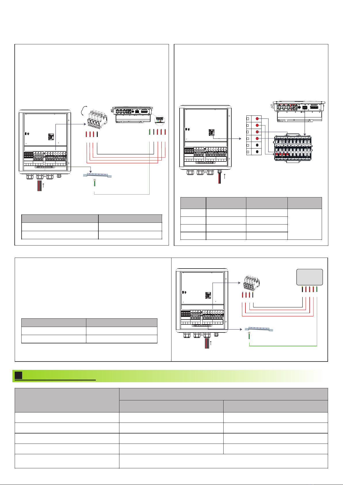
3.1.2.1 AC power cable connection:
3.1.2.2 Communication cable connection:
1. Twist the plastic cover printed with "Inverter" counterclockwise;
remove the five waterproof plugs, and reserve five holes.
2. Route the five cables of the inverter (L1/L2/L3/N/PE) through
the five holes, connect the cables to the inverter breaker terminals
(L1/L2/L3/N) and the ground copper bar. Screw torques for
tightening the inverter breaker terminals and ground terminals are
shown in the following table.
3. Finally, fasten the plastic cover clockwise. The wiring method is
shown below:
1. Twist the plastic cover printed with "COM" on the machine
counterclockwise; remove the waterproof plug, and reserve the
hole.
2. Route the two communication cables (A/B) (the twisted pair
cables are recommended) and the two BOX EN cables (EN+/EN-)
through the hole, connect them to the CN8 terminals on the control
board. Connect the other end of the cables to the COM terminals of
the inverter, and tighten the screws. The following table lists the
corresponding terminal pins. The wiring method is shown as follows:
3.1.3 Connecting SYN 100-XH-30 to the load
1. Twist the plastic cover printed with "Load" counterclockwise,
remove the five waterproof plugs, and reserve five holes.
2. Route the five load cables (L1/L2/L3/N/PE) through the five holes,
connect them to the load circuit breaker terminals (L1/L2/L3/N) and
the ground copper bar. Screw torques for tightening the load breaker
terminals and ground terminals are shown in the following table.
3. Finally, fasten the plastic cover clockwise. The wiring method is
shown to the right:
Connecting to the AC Loads
4. Indicator description
Blinking (On for 1s, and then Off for 1s)
No communication with the inverter
Blinking (on for 1s, and then Off for 1s)
When the upgrade starts, the yellow light is on or off for 10-20s, and then the yellow
light blinks at intervals of 2s (On for 1s and then Off for 1s).
5. System startup and shutdown operations
5.1 To start the system, please perform the following steps:
5.2 To shut down the system, please perform the following steps:
Shenzhen Growatt New Energy Co., Ltd.
4-13/F, Building A, Sino-German (Europe) Industrial Park,
Hangcheng Ave, Bao'an District, Shenzhen, China
+86 755 2747 1942
www.ginverter.com
T
E service@ginverter.com
W
7.
Service and contact
1. Disconnect the Inverter input breaker and the load input breaker on the SYN 100-XH-30 and then disconnect the power grid breaker.
2. Turn off the DC switch of the inverter.
3. Turn off the DC switch of the battery.
4. Wait for a while and all the indicators of the inverter, the battery, and the SYN 100-XH-30 will go off, indicating that the system is
powered off completely.
6.
Transfer to the bypass mode manually
When the SYN 100-XH-30 fails, it cannot transfer to the bypass mode automatically. To ensure uninterrupted power supply to loads, it can be
switched to the bypass mode manually.
1. Shut down the entire system. For details, please refer to Section 5.2.
2. Use a Phillips screwdriver to loosen the limit switch screw on the power bypass switch.
3. Slide the firmware to one end of the inverter switch.
4. Tighten the screw on the limit switch with a torque of 10.5 in* lbs / 1.2 N*m. Turn on the power bypass switch. The operation instructions
are shown below.
5. Power on the entire system. For details, please refer to section 5.1.
To manually transfer to the bypass mode, please proceed as follows:
1. lf the inverter is connected to a battery, turn the DC SWITCH on the battery to ON.
2. Set the DC SWITCH on the left side of the inverter to ON.
3. Turn on the inverter input breaker of the SYN 100-XH-30.
4. Enable the Backup Box function via inverter settings. For details, please refer to the XH inverter manual.
5. Turn on the grid breaker.
6. If the SYN 100-XH-30 indicator light turns green after completing the preceding steps, it indicates that the SYN 100-XH-30 is functioning
properly.
7. If you cannot power on the system with the instructions provided above, please contact Growatt.
Bypass Inverter Load Bypass Inverter Load Bypass Inverter Load
GR-UM-312-A-01
Download
Manual
Growatt New Energy
Connecting the communication cables to the XH Inverter
PE
ON
OFF
Inverter
SYN 100-XH-30
L1 L2 L3 N L 1 L2 L3 N L1 L2 L 3 N L1 L 2 L3 N
GRID BYPASS INV ERT ER LOAD
Connecting the AC cables to the XH Inverter
L1L2 L3 N
Inverter
NL1 L2
PE L3
COM
SYN 100-XH-30
L1 L2 L 3 N L1 L2 L3 N L1 L2 L 3 N L1 L 2 L 3 N
GRID BYPASS INV ERT ER LOAD
BOX.EN-
BOX.EN+
B
A
CN8
Inverter
1
6
COM