manuals.online logo
Brands
  1. Home
  2. •
  3. Brands
  4. •
  5. Growatt
  6. •
  7. Inverter
  8. •
  9. Growatt MIN 6000 TL-XH User manual

Growatt MIN 6000 TL-XH User manual

This manual suits for next models

1

Other Growatt Inverter manuals

Growatt MID 33-50KTL3-X2 User manual

Growatt

Growatt MID 33-50KTL3-X2 User manual

Growatt MID17-40KTL3-X(1) User manual

Growatt

Growatt MID17-40KTL3-X(1) User manual

Growatt 10000HYP User manual

Growatt

Growatt 10000HYP User manual

Growatt MOD TL3-XA Series User manual

Growatt

Growatt MOD TL3-XA Series User manual

Growatt SPF 3000TL User manual

Growatt

Growatt SPF 3000TL User manual

Growatt 10000UE User manual

Growatt

Growatt 10000UE User manual

Growatt 2000HF User manual

Growatt

Growatt 2000HF User manual

Growatt WIT 50-100K-AU User manual

Growatt

Growatt WIT 50-100K-AU User manual

Growatt MIN 7000TL-XE MIN 8000TL-X User manual

Growatt

Growatt MIN 7000TL-XE MIN 8000TL-X User manual

Growatt MTL-S User manual

Growatt

Growatt MTL-S User manual

Growatt ShineSEM-X User manual

Growatt

Growatt ShineSEM-X User manual

Growatt MAC 30KTL3-X LV User manual

Growatt

Growatt MAC 30KTL3-X LV User manual

Growatt MIN 2500TL-XE User manual

Growatt

Growatt MIN 2500TL-XE User manual

Growatt MAX Series User manual

Growatt

Growatt MAX Series User manual

Growatt MIN 2500TL-XH User manual

Growatt

Growatt MIN 2500TL-XH User manual

Growatt 10000UE Operating instructions

Growatt

Growatt 10000UE Operating instructions

Growatt MAX 100KTL3-X LV User manual

Growatt

Growatt MAX 100KTL3-X LV User manual

Growatt SPF 3500TL HVM-Pro User manual

Growatt

Growatt SPF 3500TL HVM-Pro User manual

Growatt MOD 3-15KTL3-X User manual

Growatt

Growatt MOD 3-15KTL3-X User manual

Growatt CP100 User manual

Growatt

Growatt CP100 User manual

Growatt 3-10KTL3-XH User manual

Growatt

Growatt 3-10KTL3-XH User manual

Growatt MOD 4000TL3-X User manual

Growatt

Growatt MOD 4000TL3-X User manual

Growatt 4000UE User manual

Growatt

Growatt 4000UE User manual

Growatt 2KVA User manual

Growatt

Growatt 2KVA User manual

Popular Inverter manuals by other brands

Omnik New Energy Omniksol-1.5k-TL user manual

Omnik New Energy

Omnik New Energy Omniksol-1.5k-TL user manual

Agilent Technologies 33250A user guide

Agilent Technologies

Agilent Technologies 33250A user guide

4-noks ZR-SWITCH-RC instruction manual

4-noks

4-noks ZR-SWITCH-RC instruction manual

V&T V5 Series user manual

V&T

V&T V5 Series user manual

Hon Turing HT-T-S1000-12 introduction

Hon Turing

Hon Turing HT-T-S1000-12 introduction

Metabo E 140 SP Plus Original operating instructions

Metabo

Metabo E 140 SP Plus Original operating instructions

BARRON EXITRONIX Tucson Micro Series installation instructions

BARRON

BARRON EXITRONIX Tucson Micro Series installation instructions

Baumer HUBNER TDP 0,2 Series Mounting and operating instructions

Baumer

Baumer HUBNER TDP 0,2 Series Mounting and operating instructions

electroil ITTPD11W-RS-BC Operation and Maintenance Handbook

electroil

electroil ITTPD11W-RS-BC Operation and Maintenance Handbook

Silicon Solar TPS555-1230 instruction manual

Silicon Solar

Silicon Solar TPS555-1230 instruction manual

Mission Critical Xantrex Freedom SW-RVC owner's guide

Mission Critical

Mission Critical Xantrex Freedom SW-RVC owner's guide

HP 3312A Operating and service manual

HP

HP 3312A Operating and service manual

Hoymiles HM-500T user manual

Hoymiles

Hoymiles HM-500T user manual

Nitecore SPM10 user manual

Nitecore

Nitecore SPM10 user manual

AEG Protect PV installation manual

AEG

AEG Protect PV installation manual

On Board TruePower Plus 1200MS owner's manual

On Board

On Board TruePower Plus 1200MS owner's manual

Plugreen PGM-200P-230 Installation and operation manual

Plugreen

Plugreen PGM-200P-230 Installation and operation manual

Fourgroup Easy use and Programming Handbook

Fourgroup

Fourgroup Easy use and Programming Handbook

manuals.online logo
manuals.online logoBrands
  • About & Mission
  • Contact us
  • Privacy Policy
  • Terms and Conditions

Copyright 2025 Manuals.Online. All Rights Reserved.

MIN 2500-6000 TL-XH
Quick Guide
Installing the Device
Connecting Cables
3.1 Installing the PV Input Power Cable
Pull the PV input power cable back to ensure that it is connected securely.
2.3 Installing the Monitor
2.2 Installing the Mounting Bracket And Min 2500-6000 TL-XH
Install Remove
Ensure that the Monitor is installed securely.
Fix the wall bracket Installation & Tighten
screw assemblies
The Inverter
Side
The Inverter
Side
The Inverter
Side
The Inverter
Side
Notice:
Before installing the device,check that the pack-
age contents are intact and complete against
the packing list.If any damage is found or any c-
omponent is missing,contact your dealer.
Overview
2.
2.1 Installation Requirements
Tilt and Space
Drilling holes
1.
3.
Connect the AC output power cable to the AC connector.
The Inverter
Side
Lock the housing
Object Description Quantity
A
B
C
D
E
F
G
1
1
1
1
2
3
1
Inverter
Mounting bracket
Quick Guide
Monitor(Optional)
Signal connector
Self-tapping screws
Safety-lock screw
Plastic expansion pipe
PV+/PV- terminal
PV+/PV- and BAT+/BAT- metal terminal
AC connector
Uninstall signal or AC connector tool
Uninstall PV or BAT terminal tool
H
J
L
I
K
M
3
2/2
3/3
1
1
1
3.2 Installing the BAT Input Power Cable
Positive metal
terminal
Positive metal
terminal
Positive connector
Positive connector
Negative metal
termina
Negative metal
termina
The Inverter Side
The Inverter Side
Pull the BAT input power cable back to ensure that it is connected securely.
The Inverter Side
The Inverter Side
Negative connector
Negative connector
3.3 Installing the AC Output Power Cable
The Inverter
side
The Inverter
side
SYS COM Port Pin Definitions
NO Definition
3.4 Installing the SYS COM Signal Cable
1
2
3
4
5
6
7
8
Enable-: Connect BDC enable signal
port negative
Enable+: Connect BDC enable signal
port positive
RS485A2:Connect Min ShineBus or Third
party monitoring equipment
RS485B2:Connect Min ShineBus or Third
party monitoring equipment
RS485A1:Signal for meter
RS485B1:Signal for meter
BAT-B: Connect BDC communication RS485B
or CANL
BAT-A: Connect BDC communication RS485A
or CANH
The Inverter
Side
Lock the housing
Suggest using 6mm2 cables Ensure the exposed core wire is totally inserted into the cable hole and connected securely.
Notice: On the right is the Australian special AC connector.
The Client Side
The Client Side
The Client Side
L---Line
N---Neutral
PE-Ground
L---Line
N---Neutral
PE-Ground
N
NL
L
PE
PE
Click!
Click!
Click!
Cables
Cables
4~6mm²
4~6mm²
Cables
Cables
4~6mm²
4~6mm²
GR-UM-162-A-02
Download
Manual
Growatt New Energy
5.
Verifying the Installation
1.When laying out signal cables, separate them from power cables to avoid strong signal interference sources.
2.Do not confuse the connector to the COM port and the connector to the SYS COM port.
3.The COM port Aonly provides a functional port-PCI or DRM.
Notice:
The Inverter
side
The Inverter
side
Unclock the housing
European Australia
NO 1 2 3 4
Function
Connect
to RRCR
+12V GND Not connected
Relay contact
2 input
Relay contact
3 input
Relay contact
4 input GND
Relay contact
1 input
Not connected Not connected
K2- output K3- output K4- output Relays common
node
K1- output
5678
COM Port Pin Definitions- Power Control Interface(PCI).
COM Port Pin Definitions- DRED connection
+12V
Function DRM3/7 DRM4/8 REFGEN COM/DRM0
DRM1/5 DRM2/6GND
NO 56781 2 3 4
7.
Powering On the System
Step2: Turn on the AC switch between the Min 2500-6000TL-XH and
the power grid.
Step3: When the OLED show ”Country/Area VDE0126”, Please Set the
country follow the below step4.
Step4: Single touch to switch Country, such as N4105, Then jump to step6.
Step5: Single touch to switch Country, such as Newzealand.
When the OLED show ”Country/Area Australia”, Please Set the country
follow the step5
Step6: Press the touch key for 5s or No operation on the OLED
for more than 30S (The country of the current interface is
selected by default)the OLED shows Country setting is complete.
If the LED light is green, the system is operating normally.
You can reset the country by “Set Country” in the submenu of “Set
parameter”.
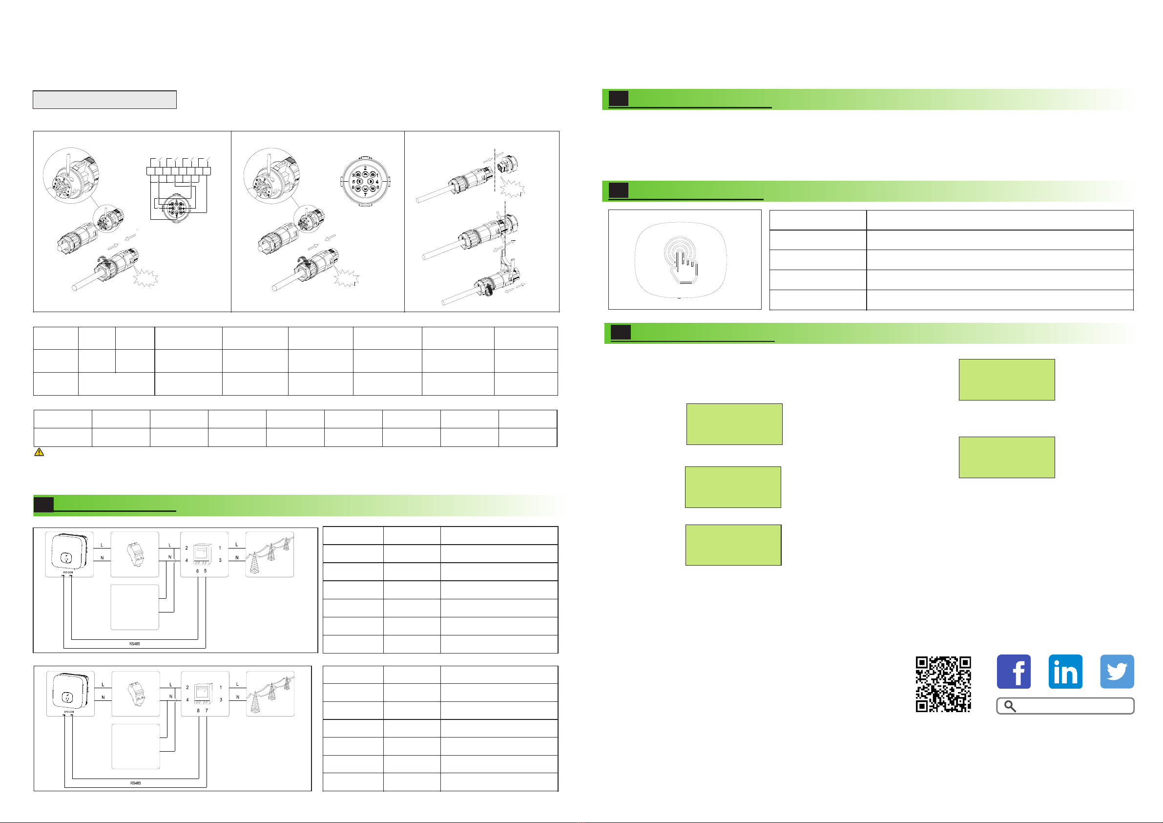
3.5 Installing the COM Signal Cable
We use 8Pin COM Port Connector as Power Control Interface(PCI) for European models or Connector as inverter DRED connection(DRM)
for Australia.
Connecting Meter
4.
The following table describes how we can connect EASTRON meter (SDM230-Modbus)to inverter:
The following table describes how we can connect CHINT meter (DDSU666) to inverter:
Tips
Meter Pin NO. Description Connect to Inverter
1
2
3
4
5
6
L-in
L-out
N-in
N-out
RS485A
RS485B
/
AC connector & Load L
/
AC connector & Load N
SYS COM Pin 5 RS485A1
SYS COM Pin 6 RS485B1
Meter Pin NO. Description Connect to Inverter
1
2
3
4
7
8
L-in
L-out
N-in
N-out
RS485A
RS485B
/
AC connector & Load L
/
AC connector & Load N
SYS COM Pin 5 RS485A1
SYS COM Pin 6 RS485B1
56
Country/Area
Australia
Country/Area
N4105
Country/Area
N4105
Country/Area
Newzedland
Country/Area
VDE0126
Set OK
Step1: Turn on the DC switch at the bottom of the Min 2500-6000TL-XH.
6.
1.The Min 2500-6000TL-XH is installed correctly and securely.
2.The Monitor is installed correctly and securely.
3.The Ground cable is connected correctly and securely.
4.The DC switch and all the switches connecting to the Min 2500-6000TL-XH are OFF.
5.The AC output power cable, PV&BAT input power cable and signal cable are connected correctly and securely.
6.Unused terminals and ports are locked by watertight caps.
Button touch operation
Touch button
Single touch
Double touch
Three touch
Hold 5s
Description
Switch display or Number +1
Enter
Previous menu
Confirm country setting or Number recover defaut value
Click!
Click!
Click!
RRCR
PCI Connector
K1 K2 K3 K4
1 2 345678
56
LOAD
LOAD
Shenzhen Growatt New Energy Co., Ltd
4-13/F,Building A,Sino-German(Europe) Industrial Park,
Hangcheng Ave,Bao’an District, Shenzhen, China
+86 0755 2747 1942
www.ginverter.com
T
E
W
service@ginverter.com