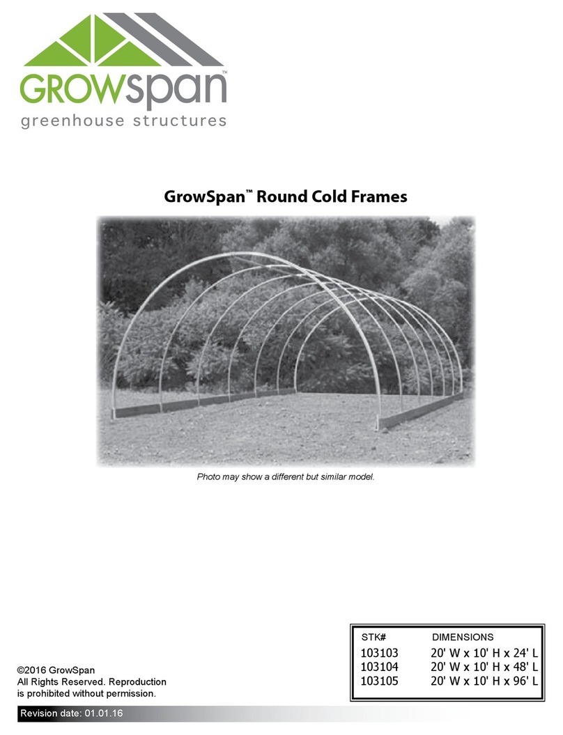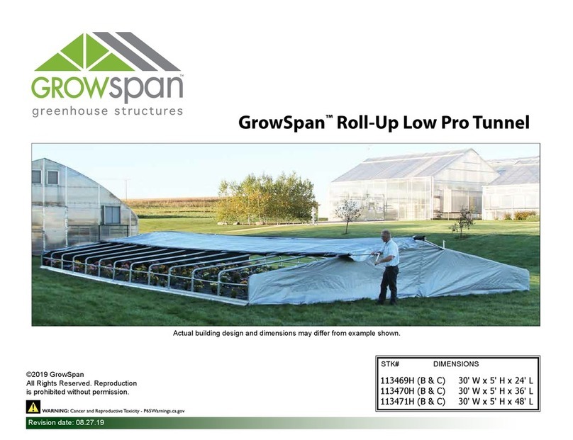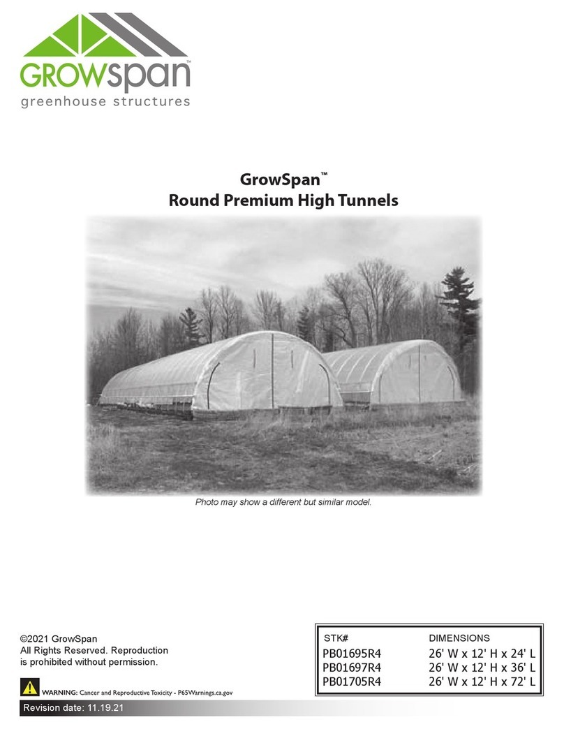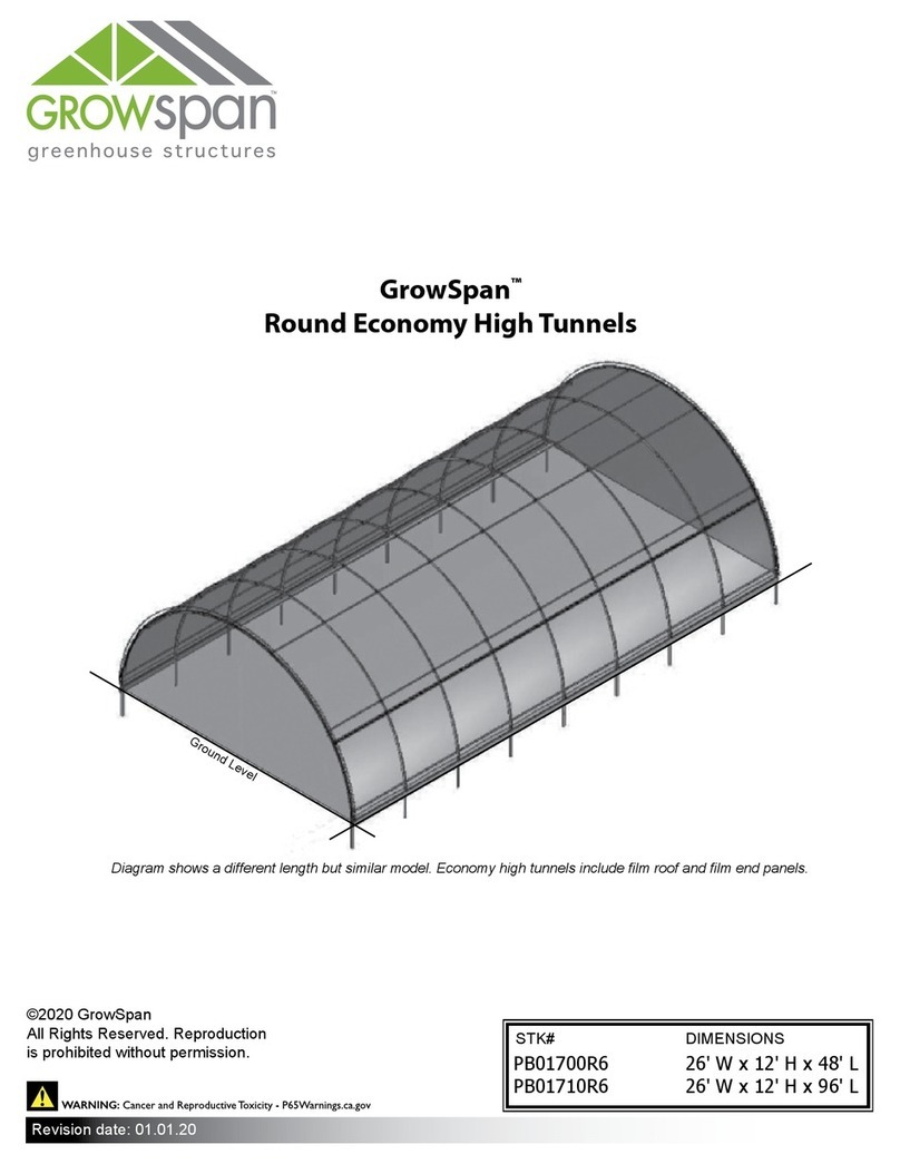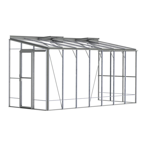
GROWSPAN™COLD FRAMES & GREENHOUSES
2Revision date: 05.08.18
YOU MUST READ THIS DOCUMENT BEFORE YOU
BEGIN TO ASSEMBLE THE SHELTER.
Thank you for purchasing this Commercial cold frame.
When properly assembled and maintained, this product will
provide years of reliable service. These instructions include
helpful hints and important information needed to safely
assemble and properly maintain the cold frame. Please
read these instructions before you begin.
If you have any questions during the assembly, contact
Customer Service at 1-800-245-9881 for assistance.
SAFETY PRECAUTIONS
• Wear eye protection.
• Wear gloves when handling panels and frame parts.
• Use a portable GFCI when working with power tools
and cords.
• Do not climb on the cold frame during or after
construction.
• Provide adequate ventilation if the structure is
enclosed.
• Do not store hazardous materials in the cold frame.
ANCHORING INSTRUCTIONS
Prior to assembling this cold frame, please read the MUST
READ document included with the shipment.
WARNING: Strong winds can cause the cold frame to
shift if it is not adequately secured to the site.
The site on which the cold frame is constructed will
determine the anchoring method that is required.
Consult a professional contractor to determine the best and
safest way to anchor the frame.
Contact your sales representative at 1-800-245-9881 for
anchoring suggestions.
WARNING: To prevent property damage and serious
personal injury, the assembled cold frame must be
anchored to the site.
LOCATION
Choosing the proper location is an important step before
you begin to assemble the cold frame.
The following suggestions and precautions will help you
determine whether your selected location is the best
location.
• This cold frame has a metal frame. Never erect the
cold frame under power lines or near fuse boxes or
sources of electricity.
• Identify whether underground cables and pipes are
present before preparing the site or anchoring the
cold frame.
• Location should be away from structures that could
cause snow to drift on or around the cold frame.
• Do not position the cold frame in a place where large
loads such as snow and ice, large tree branches, or
other overhead obstacles could fall.
SITE
After choosing a location, proper preparation of the site is
essential. The following site characteristics will help ensure
the integrity of the cold frame.
• For best results, the site must be level to properly and
safely erect and anchor the cold frame.
• Drainage: Water draining off the cold frame and from
areas surrounding the site should drain away from the
site to prevent damage to the site, the cold frame, and
contents of the cold frame.
WARNING: The individuals assembling this cold frame
are responsible for designing and furnishing all
temporary bracing, shoring and support needed
during the assembly process (if applicable). For safety
reasons, those who are not familiar with recognized
construction methods and techniques must seek the
help of a qualified contractor.
