manuals.online logo
Brands
  1. Home
  2. •
  3. Brands
  4. •
  5. GrowSpan
  6. •
  7. Greenhouse Kit
  8. •
  9. GrowSpan 113170 User manual

GrowSpan 113170 User manual

1
Revision date: 02.17.17
©2017 FarmTek®
All Rights Reserved. Reproduction
is prohibited without permission.
EZ-Shade Tarp Arm
#113170
Finished Grade
Features Description
Adjustable Arm Extends from 8' to 12' in 4' increments
(when anchored to base plate).
Maximum Building Height 10' to 10' 6"
Maximum Building Width 20'
2Revision date: 02.17.17
TOOLS
The following list identifies the tools needed
for assembly. Additional tools may be needed
depending on application.
• Tape measure and gloves.
• Marker to mark locations on concrete pier.
• Tool to punch holes through fabric or film.
• Wrench set and socket and ratchet set that
includes 9/16" and 15/16" tools.
• 3/4" masonry bit to drill mounting holes for
3/4" anchor bolts.
READ THIS DOCUMENT BEFORE YOU BEGIN
This guide provides helpful hints and important information needed to safely assemble and properly use the 113170 EZ-Shade Tarp Arm. Read and
understand this guide before you begin.
Important Information
SAMPLE ASSEMBLY PROCEDURE
Steps outlining the assembly process are as follows:
1. Verify that all parts are included in the shipment.
Notify customer service with questions or
concerns.
2. Read these instructions and all additional
documentation included with the shipment
before you begin.
3. Gather the tools and assistants needed for
assembly.
BASIC CARE AND MAINTENANCE
Proper care and maintenance is important. Check
the following items periodically:
• Check all fasteners that secure cover material to
the tarp arms to ensure they are tight.
• Grease the pivot bolt every 6 months or more
depending on use and conditions.
• Check mounting hardware to ensure that all
fasteners remain tight.
CUSTOMER-SUPPLIED MATERIALS
Additional parts, materials, and equipment are
supplied by the customer/contractor:
• Concrete for concrete piers. Minimal pier
dimensions: Diameter: 12"; Height: 24"
• Equipment to dig holes for piers and wrench to
tighten anchor bolts.
• Cover material to cover shelter.
• Fasteners and materials to attach cover material
to shelter frame.
• Materials to construct an anchor for each pivot
arm when cover material is pulled over frame.
SAFETY PRECAUTIONS
• Use a portable GFCI (Ground Fault Circuit
Interrupter) when working with electric power
tools and cords. Use battery-powered tools if
possible.
• Exercise caution when using all tools.
• Wear gloves and eye protection.
WARNING: THE 113170 EZ-SHADE
TARP ARM AND ATTACHED COVER
MATERIAL ARE HEAVY! FAILURE TO
FOLLOW THESE PRECAUTIONS CAN
RESULT IN PROPERTY DAMAGE OR
SERIOUS INJURY:
• DO NOT OPERATE THE PIVOT ARMS
WITHOUT ASSISTANCE. NEVER
OPERATE ALONE.
• WIND CAN DAMAGE COVER AND
PIVOT ARM ASSEMBLY. DO NOT
ATTEMPT TO COVER OR UNCOVER THE
SHELTER DURING WINDY OR STORMY
CONDITIONS.
• ANCHOR THE ASSEMBLY TO THE
GROUND AFTER PULLING COVER OVER
THE SHELTER. DO NOT ALLOW THE
COVER MATERIAL AND PIVOT ARMS TO
REMAIN UNSECURED AFTER COVER IS
PULLED INTO PLACE.
• INSPECT PIVOT ARMS AND ALL
FASTENERS BEFORE EACH USE TO
ENSURE ALL ARE TIGHT.
• INSPECT THE AREA AROUND THE
SHELTER TO ENSURE NO ONE OR
NOTHING IS PRESENT WHEN PULLING
OR REMOVING THE COVER MATERIAL.
• GRAVITY PULLS PIVOT ARMS TOWARD
THE GROUND. WIND CAN SLOW OR
SPEED THIS MOVEMENT. EXERCISE
CAUTION DURING OPERATION.
• ANCHOR PIVOT ARMS TO THE
GROUND WHEN EXTREME WEATHER IS
EXPECTED.
WARNING: NEVER LEAVE THE PIVOT
ARMS IN A VERTICAL OR ANGLED
POSITION. ARMS MUST REMAIN ON
THE GROUND AT ALL TIMES.
3
Revision date: 02.17.17
Top View of Sample Cold Frame
Diagram below shows the top view of a sample cold frame. The 113170 tarp arms are installed at each end of the frame and are anchored to customer-
supplied concrete piers. Consult the remainder of this guide for additional details.
WARNING: NEVER LEAVE THE PIVOT
ARMS IN A VERTICAL OR ANGLED
POSITION. ARMS MUST REMAIN ON
THE GROUND AT ALL TIMES.
Maximum Extension: 12'
Maximum building width: 20'.
4Revision date: 02.17.17
1
Assembly Instructions
CONSTRUCT CONCRETE PIERS FOR THE BASE PLATES
Complete these steps:
1. Review the diagrams on this page to layout the pier positions at each end of building frame.
NOTE: If building includes closed ends and pedestrian doors, review the drawings showing these features. Set the
piers far enough away from the end walls to allow doors to fully open when shade material or film is pulled into place.
2. Contact a local contractor to construct concrete piers. Follow all established codes for the region. Minimum dimensions:
Diameter @ 12"; Height @ 24". See diagram at the right. Align piers with the center of the frame at each end.
3. While concrete sets, continue with the assembly.
ATTENTION: For shelters with an end wall and door, position pier and pivot
arm mounting base in a location that allows door to fully open when in use.
Align center of pier with center of shelter. Set top of pier at finished grade.
Finished Grade
Pier
Center of Frame
Shelter with Door Installed
For most cold frame
applications where
no door is present
in an end wall,
minimum distance
from center of end
rafter to center of
pier is 18".
Minimum is 18".
Shelter without Door
Top View
Concrete
Pier
12"
24" minimum
Concrete Pier
Finished Grade
5
Revision date: 02.17.17
2
Assembly Instructions
ASSEMBLE THE 113170 EZ-SHADE TARP ARM
Complete these steps:
1. Cosult the diagram on this page and construct the 113170 canopy arm
assemblies. Use these fasteners to attach the 113166 brackets.
Part Number Description Quantity
FAG363B HEX CAP 3/8X3" ZINC EACH 8
FAME08B BULK FLATWASH 3/8" ZINC (ea) 16
FALB04B NUT 3/8-16 ZNC EACH 8
112317 2" SQUARE CAP PLUGS 4
2. Install the 112317 plugs in each end of the assembled tube as shown.
113167
113166
113175
112317
6Revision date: 02.17.17
2
Assembly Instructions
ASSEMBLE THE 113170 EZ-SHADE TARP ARM—continued
3. Connect the canopy arms to the 113176 pivot arms.
ATTENTION: Measure the height of the shelter frame and adjust the pivot
arms to be approximately 18" higher. See diagram for details.
Part Number Description Quantity
FAG363B HEX CAP 3/8X3" ZINC EACH 4
FAME08B BULK FLATWASH 3/8" ZINC (ea) 8
FALB04B NUT 3/8-16 ZNC EACH 4
113165 TUBE CLAMP BUSHING 4
4. Continue with the next procedures.
Finished Grade
Step 2
Frame Height
+18"
Pivot Arm Assembly
Frame
height
plus
18".
Canopy Arm Assembly
113176
Pivot Arm
113165
After required length is
determined, align mounting
holes, insert 113165 bushings,
and secure connection using
fasteners identified in the table.
Maximum building
height: 10' to 10' 6".
Maximum building width: 20'.
7
Revision date: 02.17.17
3
Assembly Instructions
ATTACH PIVOT ARM ASSEMBLY TO BASE AND ANCHOR BASE TO PIER
Complete these steps:
1. Connect each pivot arm assembly to a mounted base plate using the fasteners noted below. Apply a thin film of grease to each bolt before installing.
Part Number Description Quantity
104804 5/8" x 5" A325 HEAVY HEX BOLT GLV 2
108851 WASHER 5/8" F436 GALV A325 4
104806 5/8"-11 DH GRADE HD HEX NUT GALV A325 2
ATTENTION: Tighten the bolt and nut until snug. Pivot arm should swing freely
when bolt is tight.
After tightening fastener, grease the bushing to ensure the connection is
properly lubricated. Use a multi-purpose grease.
Apply thin film
of grease.
2. Verify that concrete has set and mark the anchor bolt locations on the pier. Use the pivot arm assembly to position the base correctly. See diagram below.
3. After marking the anchor bolt locations, drill the bolt holes in the pier
using a 3/4" masonry bit. Install pivot arm
assemblies parallel
with the rafter at each
end of the frame.
Dimensions from the
building rafter to the
pivot arm assembly
will be the same
throughout the length
of the pivot arm when
installed correctly.
End
Rafter
NOTE: Do not drill concrete if it has
not set. Doing so may cause it to crack
when anchor bolts are driven into place.
4. Set base in place and drive anchor bolts
into mounting holes.
5. Tighten the nuts to secure the assembly
to the pier.
6. Repeat the steps to attach the remaining
base plate to the remaining pier.
7. Continue with the next procedure.
FAW605
Anchor Bolt
8Revision date: 02.17.17
4
Assembly Instructions
ATTACH COVER MATERIAL
Complete these steps:
1. Determine which direction you want to pull the cover material over the
shelter, position material along frame, and secure to frame.
NOTE: Attaching a baseboard at ground level throughout the length
of the shelter and then securing cover material to that baseboard
is recommended. Contact your sales representative for additional
suggestions or to purchase additional materials. In some instances, it may
be best to pull the material over the frame, attach the edge to the building,
then attach the other edge to the canopy arms.
2. Take both pieces of the 8' u-channel (111948) and cut each one in half.
Shade Material
Step 1
Finished Grade
Customer-supplied
baseboard to secure
material to one side of
the building.
Shade Material
Attach material edge
here and at the other
end of the shelter.
113171
111948
3. Attach one piece of u-channel to each edge of fabric clamp (113171). See
the diagrams above.
The example shows a film-covered greenhouse where the shade material
is pulled over the building using the 113170 EZ-Shade Tarp Arm.
HINT: With assistance, pull material over frame, attach one edge to
building, then attach remaining edge to each pivot arm.
DO NOT ATTEMPT TO PULL MATERIAL ON A WINDY OR STORMY
DAY OR WHEN SUCH CONTITIONS ARE EXPECTED.
9
Revision date: 02.17.17
Part Number Description Quantity
FAH322 CARR BOLT 5/16X3-1/2 GLV B100 12
FAME51B FLATWASHER 5/16" GLV /EA BULK 12
FALB32B NUT HOTDIP GLV 5/16-18 EACH 12
4
Assembly Instructions
ATTACH COVER MATERIAL
4. Stretch material out and attach the free edge to the canopy arms.
Fold the material edge 3-4 times (minimum) and sandwich that edge
between the canopy arm and the fabric clamp. Use hand clamps (or
similar tools) to hold fabic and fabric clamp in place to install bolts.
5. Take a sharp tool and punch a hole in the materail at each bolt location.
6. Insert the 5/16" carriage bolts throught the fabric clamp and install the flat washers and nuts.
Tighten all fasteners.
7. Repeat steps to secure cover material to the remaining canopy arm at the other end of the shelter.
8. With assistance, test the system as shown on the following page.
Amount of material that extends
beyond the edge of canopy arm
depends on shelter width and height.
END VIEW—CANOPY ARM AND
SHADE MATERIAL CONNECTION:
Diagram above shows edge of cover
folded and sandwiched between the
canopy arm tube and the fabric clamp.
FAH322
111948
FAME51B
FALB32B
113171
Material
Canopy
Arm
10 Revision date: 02.17.17
5
Assembly Instructions
TEST THE 113170 EZ-SHADE TARP ARM
4
ATTENTION: Clear all area around the shelter before operating.
3
IMPORTANT: Anchor both pivot arms to the
ground to prevent damage and injury when
material is pulled over shelter.
With assistance, lift one pivot
arm with attached cover.
1
WARNING: NEVER LEAVE THE PIVOT ARMS IN A VERTICAL OR ANGLED
POSITION. ARMS MUST REMAIN ON THE GROUND AT ALL TIMES.
2
Carefully pivot the arm and
material to the ground.
11
Revision date: 02.17.17
Customer Note Page

Other GrowSpan Greenhouse Kit manuals

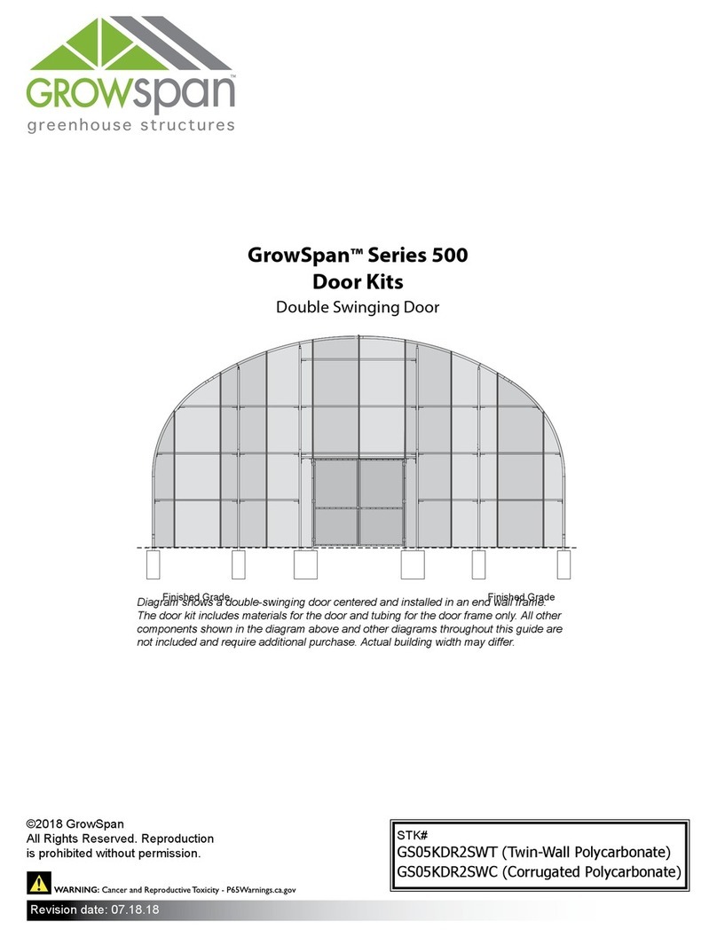
GrowSpan 500 Series User manual

GrowSpan

GrowSpan 500 Series User manual

GrowSpan 104176 User manual

GrowSpan

GrowSpan 104176 User manual

GrowSpan 105148 User manual

GrowSpan

GrowSpan 105148 User manual

GrowSpan Twist-of-the-Wrist User manual

GrowSpan

GrowSpan Twist-of-the-Wrist User manual

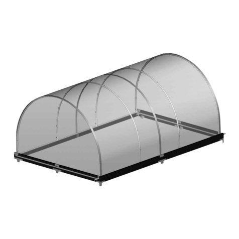
GrowSpan Canopy-Top Cold Frame Series User manual

GrowSpan

GrowSpan Canopy-Top Cold Frame Series User manual

GrowSpan PB01750R6 User manual

GrowSpan

GrowSpan PB01750R6 User manual

GrowSpan PB01695R4 User manual

GrowSpan

GrowSpan PB01695R4 User manual

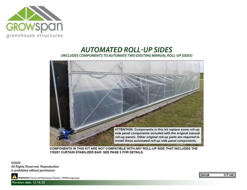
GrowSpan 117149 User manual

GrowSpan

GrowSpan 117149 User manual

GrowSpan 500 Series User manual

GrowSpan

GrowSpan 500 Series User manual

GrowSpan 106205 User manual

GrowSpan

GrowSpan 106205 User manual

GrowSpan 106363 User manual

GrowSpan

GrowSpan 106363 User manual

GrowSpan 105175F User manual

GrowSpan

GrowSpan 105175F User manual

GrowSpan 2000 Series User manual

GrowSpan

GrowSpan 2000 Series User manual

GrowSpan Round Premium PB01660R4 User manual

GrowSpan

GrowSpan Round Premium PB01660R4 User manual

GrowSpan PB01700R6 User manual

GrowSpan

GrowSpan PB01700R6 User manual

GrowSpan 500 Series User manual

GrowSpan

GrowSpan 500 Series User manual

GrowSpan 2000 Series User manual

GrowSpan

GrowSpan 2000 Series User manual

GrowSpan 500 Series User manual

GrowSpan

GrowSpan 500 Series User manual

GrowSpan 116675 User manual

GrowSpan

GrowSpan 116675 User manual

GrowSpan 115020 User manual

GrowSpan

GrowSpan 115020 User manual

GrowSpan Gothic Premium 108179H User manual

GrowSpan

GrowSpan Gothic Premium 108179H User manual

GrowSpan 113463H User manual

GrowSpan

GrowSpan 113463H User manual

GrowSpan 500 Series User manual

GrowSpan

GrowSpan 500 Series User manual

GrowSpan Flip-Top Cold Frame User manual

GrowSpan

GrowSpan Flip-Top Cold Frame User manual

Popular Greenhouse Kit manuals by other brands

Halls 42 2 Assembly

Halls

Halls 42 2 Assembly

RHINO Premium Assembly instructions

RHINO

RHINO Premium Assembly instructions

Bloomengine B100KHB manual

Bloomengine

Bloomengine B100KHB manual

Rion Eco Grow Assembly instructions

Rion

Rion Eco Grow Assembly instructions

Juliana Premium Wall 13 Assembly instructions

Juliana

Juliana Premium Wall 13 Assembly instructions

ModuLaro AIGLE GH202000 Assembly instruction

ModuLaro

ModuLaro AIGLE GH202000 Assembly instruction

Robinsons Victorian RANBY 7 Assembly instructions

Robinsons

Robinsons Victorian RANBY 7 Assembly instructions

Vitavia Calypso 3000 Assembly instructions

Vitavia

Vitavia Calypso 3000 Assembly instructions

Holman GH1001 instruction manual

Holman

Holman GH1001 instruction manual

LAMS MELISSA 7,20 M2 Assembly instructions

LAMS

LAMS MELISSA 7,20 M2 Assembly instructions

Velcom CAMELLIA R Technical manual

Velcom

Velcom CAMELLIA R Technical manual

Vitavia Triton 5000 quick start guide

Vitavia

Vitavia Triton 5000 quick start guide

Palram Applications Harmony 6x8 instructions

Palram Applications

Palram Applications Harmony 6x8 instructions

Redpath Statesman Series Instructions & Illustrations

Redpath

Redpath Statesman Series Instructions & Illustrations

Konifera SF2500 Assembly instructions

Konifera

Konifera SF2500 Assembly instructions

greenhouse sensation GeoPod Heated Setup instructions

greenhouse sensation

greenhouse sensation GeoPod Heated Setup instructions

OLT SSGS812 Assembly manual

OLT

OLT SSGS812 Assembly manual

Vitavia Hera 2 9000 Assembly instructions

Vitavia

Vitavia Hera 2 9000 Assembly instructions

manuals.online logo
manuals.online logoBrands
  • About & Mission
  • Contact us
  • Privacy Policy
  • Terms and Conditions

Copyright 2025 Manuals.Online. All Rights Reserved.