GSi 2000 Series User manual

Series 2000 Top Dry
Heater Control
Operator's Manual
PNEG-743
Date: 5-3-2006
PNEG-743

3
Series 2000 Top Dry Heater Control TABLE OF CONTENTS
Safety ..................................................................................................................4
Safety Decals........................................................................................................5
Fan And Heater Operating Procedure....................................................................6
Setup And Configuration...........................................................................6
Power Up...................................................................................................6
Normal Operating Displays Heater Not Running......................................6
Programming Top Dry Plenum And Grain Temperatures........................7
Programming Top Dry-Dry And Cool Timers..........................................8
Programming Top Dry Fan Delay For Slaves..........................................8
Setting Gas Pressure.................................................................................9
Running The Dryer....................................................................................10
Run hours Display.....................................................................................10
Top Dry Quick Start Procedure..............................................................................12
Drying Rates For Shelled Corn..............................................................................13
Factory Configuration............................................................................................14
Configuration Dip Switches (Normally Done At GSI)............................14
Error Conditions....................................................................................................15
Limit Switches...........................................................................................15
Misc Error Numbers.................................................................................15
Multiple Heater Error Conditions.............................................................15
Warranty.................................................................................................................16

4
Series 2000 Top Dry Heater Control
GSI cannot warrant any roof damages due to excessive
vacuum or internal pressure caused by fans or other air
moving systems. Adequate ventilation and/or "makeup
air" devices should be provided for all powered air han-
dling systems. GSI does not recommend the use of down-
ward flow systems (suction). Severe roof structural dam-
age can result from any blockage of air passages. Run-
ning of fans during certain high humidity/cold weather
conditions can cause freezing over of air exhaust or in-
take ports.
Roof Damage Warning
SAFETY
Thank you for choosing a GSI product. It is de-
signed to give excellent performance and service
for many years.
This manual describes the operation of the
Series 2000 Top Dry Heater Control Unit. Dif-
ferent models are offered, including a 36" diam-
eter and a 42" diameter, with a choice of horse-
power available on the fan motor.
The principal concern of the GSI Group, Inc.
("GSI") is your safety and the safety of others asso-
ciated with grain handling equipment. This manual
ment. Such alterations may produce a very dan-
gerous situation, where serious injury or death
may occur.
Heater Operation
is written to help you understand safe operating pro-
cedures, and some of the problems that may be en-
countered by the operator or other personnel.
As owner and/or operator, it is your respons-
ibility to know what requirements, hazards and
precautions exist, and to inform all personnel as-
sociated with the equipment, or who are in the
heater area. Avoid any alterations to the equip-

5
Series 2000 Top Dry Heater Control SAFETY ALERT DECALS
The GSI Group, Inc. recommends
contacting your local power company,
and having a representative survey your
installation so the wiring is compatible
with their system, and adequate power
is supplied to your unit.
Safety decals should be read and
understood by all people in the grain
handling area. The bottom right de-
cal should be present on the inside
bin door cover of the two ring door,
24" porthole door cover and the roof
manway cover.
If a decal is damaged or is miss-
ing contact:
The GSI Group, Inc.
1004 E. Illinois St.
Assumption, IL 62510
217-226-4421
A free replacement will be sent to you.

6
Series 2000 Top Dry Heater Control
OPERATING PROCEDURE
There are three possible configuration modes for
the Top Dry.
1. Stand alone heater control. Master control is
located on fan/heater and no other control is neces-
sary. Running fan/heater in this mode requires
climbing up to fan/heater to start unit and adjust con-
trols.
2. Econo control center. In this case the control is
located up on the fan/heater and has been pre-pro-
grammed. Power is then applied from a switch be-
low. The start switch is a momentary switch that is
attached to J7-7 connector. The dryer is started by
depressing that momentary switch. Note, that in this
mode, the display is remote, therefore error condi-
tions will shut the dryer down but cannot be viewed
unless you climb up and look at the display.
Limit switches are checked upon power up. The
control checks all the limit switches. If a limit switch
has become open circuit the control displays which
limit is open circuit. The control will not operate
with a limit switch error. The fan will not turn on
with an error condition. There is no way to bypass
an error condition. It must be fixed (see errors page
22). The air switch is also checked on power up.
The air switch should indicate no airflow. This is
neces-sary to check the function of the air-
Power Up
Normal Operating Displays
Heater Not Running
The main display shows either dry time (lower left
cursor), cool down time (lower 2nd from left cur-
sor), plenum (lower 2nd from right cursor) or grain
temperature (lower right cursor). The "mode select"
switch (fan bypass) is used to select the mode to be
The control panel of the Top Dry heater unit.
Setup And Configuration
3. Manual control center. In this case the master
control is up on top where all the sensors and limits
are attached. The remote display below is attached
via a serial 2 wire link. The remote display is used
to program the master, view errors and start the
dryer. In essence, the remote display is just a slave
extension of the master.
flow switch. The air switch error on power up can-
not be bypassed since, in the Top Dry system, the
fan is controlled by the heater control.
If multiple heaters are tied together, and the
master detects that the slaves fan is on (the air switch
stuck?), the master will lock up displaying "SLA
ERROR".

7
Series 2000 Top Dry Heater Control OPERATING PROCEDURE
flashing. Use the up and down arrow switches to
program the temperature.
This first temperature setting is the temperature
at which the entire burner shuts off--no flame. De-
pressing the program switch again will cause the
display to advance to setting the cycle temperature
(upper 2nd from left cursor flashing). This tem-
perature setting is the temperature above which the
heater goes to low flame. Depressing the program
switch again will cause the display to advance to
thegrain temperature limit setting (upper 2nd
Setting the plenum hi limit on the control box.
"AIRFLOW" or "NO AIRFLOW" is displayed
if air is flowing or not flowing. "RX TX" is dis-
played if there is a master with remote.
The limits are continuously checked during
the off mode. A limit switch open or any other
error condition will cause the display to show the
limit or error condition. When the dryer is not
running, if the limit or error condition is corrected,
the LCD returns to its normal display. This is not
the case with an error or limit condition during
the drying operation. This causes the display to
lock up in the error display mode, the dryer
stops running, and the error must be corrected.
The toggle switch must then be shut off and
Depress the program temperature switch on either
the master or remote. The upper left cursor will be
Programming Top Dry Plenum
And Grain Temperatures
displayed. Note, that the cursors don't flash when
in the normal display. They do flash when in the
program mode.
The dry and cool time shown on the display is
turned on again (see section on "Running the
Dryer" page 18, for mode explanation).

8
Series 2000 Top Dry Heater Control
OPERATING PROCEDURE
from right cursor flashing).
When the grain temperature
gets to this point (or dry timer
times down), the heater control
advances to the cool cycle. If
Depressing the program dry and
cool times switch will cause the
lower left cursor to begin flash-
ing, indicating a new dry time
may be entered. This dry time is
the length of time the heater will
run in the dry mode (burners con-
trolling to the temperature set in
the above program mode). This
time can be set from 1.0 hours to
20.0 hours. Depressing the pro-
gram dry and cool times switch
again will cause the lower 2nd
from left cursor to begin flashing.
Programming Top Dry-
Dry And Cool Timers
Fan delay time is the amount of time in seconds between the fans
starting. Power up with the "Program Dry/Cool Timers" and " Pro-
gram Temperatures" switches depressed to adjust the programmable
Programming Top Dry Fan Delay For Slaves
to adjust the programmable delay for Top Dry fans.
The dry time and cool time "carrots" on the display both flash
indicating it is in the program delay time mode.
Note: This can only be done on the master.
continue to run cool. This cool time can be set from 0.0 hours to 20.0
hours. If set to 0.0 hours, there is no cool period. Depressing the
program dry and cool times switch again will cause the control to exit
the program mode.
Setting the dry time on the control box.
This is the cool period. When the burners get shut down due to the
dry timer timing out, or grain reaching temperature set point, the fan
will
no cool time is pro-
grammed in, the
dryer shuts down
when the grain gets
to that temperature.
Depressing the
program switch
again will cause the
display to advance
to setting the dif-
ferential tempera-
ture setting (upper
right cursor flash-
ing). This differen-
tial is basically
hysteresis. When
main or cycle solenoids shut off due to exceeding the temperature
set point, that burner will not come on again until the temperature
falls below the set point minus temperature differential. Depress-
ing the program switch again will cause the control to exit the pro-
gram mode.

9
Series 2000 Top Dry Heater Control OPERATING PROCEDURE
1. At fan/heater turn toggle
switch to "ON" position. If
using a remote display or
econo start, place that toggle
switch in the "ON" position
also.
2. Press the increase and de-
crease buttons at the same
time to reset.
3. Press the "PROGRAM TEM-
PERATURE" button.
4. Use the increase or decrease
button to set the "PLENUM
HIGH LIMIT SET POINT"
to desired setting (160°-
200°).
5. Press the "PROGRAM TEM-
PERATURE" button to con-
tinue to set the "CYCLE SET
POINT".
6. Use the increase or decrease
buttons to set the "CYCLE
SET POINT" to desired set
ting (140°-180°).
Setting Gas Pressure
Set grain temperature on control
panel display.
8. Use the increase or decrease buttons to set "GRAIN TEMPERA-
TURE SET POINT" to 140°.
9. Press the "PROGRAM TEMPERATURE" button to continue
to set the "TEMPERATURE DIFFERENTIAL".
10. Use the increase or decrease buttons to set the "TEMPERATURE
DIFFERENTIAL" to 10°.
11. Open all manual gas shut off valves, on and to the fan/heater unit.
12. Press the start button.
13. Make sure that the blade is spinining in the right direction. If not
place the toggle switch in the "OFF" position and correct the problem.
14. After the fan reaches full speed the display should read "AIR-
FLOW" in the upper right hand corner and "PURGING" in the
lower left corner.
15. After 10 seconds the burner should ignite. If not, turn "OFF" the
toggle switch and then back "ON". Repeat 12-15.
16. When the burner ignites the display should read "HI-FLAME" at
the left of the display. Loosen the nut on the main regulator and turn
screw in, to increase pressure and out to decrease pressure. The
pressure gauge should be set at 10-15 lbs. for LP units, or 4-6 lbs.
for natural gas units.
Airflow and
purging on
control
panel
display.
7. Press the "PROGRAM TEMPERATURE" button to contine to
set the "GRAIN TEMPERATURE SET POINT".

10
Series 2000 Top Dry Heater Control
OPERATING PROCEDURE
shut down, and then the fan will shutdown. If a
limit opens or an error condition occurs during dry-
ing, the control will lockup in the error display
mode. Power must be shut off and back on to clear
the error condition, even when the error or limit that
caused the shut down has been corrected.
The main display shows either dry run time
(lower left cursor), cool down time (lower 2nd
from left cursor), plenum (lower 2nd from right
cursor) or grain temperature (lower right cursor).
The "mode select" (fan bypass) is used to select
the mode to be displayed. Note, that the cursors
do not flash when in the normal display. They do
flash when in the program mode (see page 18).
The dry and cool down shown on the display is
the amount of time remaining in the dry or cool pe-
riod. Note, that if unit is in the dry time period,
you cannot view the cool time remaining, since the
unit is not in the cool period. However, the cool
period may be altered or viewed by entering the pro-
gram mode. The same is true if the heater control is
in the cool period. You cannot view the dry run time,
since that time has already expired.
20. Increase the cycle set point to return to high flame.
21. Turn off fan/heater by placing the toggle switch in
the "OFF" position.
22. Repeat process on second fan/heater if appli-
cable.
23. Watch heater run several minutes to make sure
it cycles between hi and lo flame properly.
24. Hi-flame pressure should be adjusted so plenum
reaches cycling temperature easily.
25. Lo-flame should be adjusted so temperature
drops slowly, until switching back to high flame.
Running The Dryer
Run Hours Display
Run hours are recorded when the controller detects
that the fan is on (airflow). The hours may be viewed
by depressing the "HOURS" to get hours and
"HOURS X 1000" to get the number of 1000 hours
accumulated.
17. Press the "PROGRAM TEMPERATURE" but-
ton to change the temperature set points. Press it
again to change the "CYCLE SET POINT".
The display should read 160°.
18. Decrease the "CYCLE SETPOINT TEMPERA-
TURE" until the heater cycles to low flame.
19. Open or close the low cycle ball valve until the gas
pressure is 3-5 lbs. for LP, or 1-2 lbs. for natural gas.
The display will indicate "FLAME" when flame is sensed.
If no flame is sensed the "FLAME" message will be off.
The display indicates what part of the cycle it is in. The
display will indicate whether it is in the "HI-FLAME" or
"LO-FLAME" part of the cycle (see "Programming Top
Dry PlenumAnd Grain Temperatures" page 15, for set-
ting the HI/LO-FLAME temperature). If the tempera-
ture is above the high temperature setting, the flame will
be off, the "FLAME" message will be out and the dis-
play will be flashing "OFF-CYCLE".
The limits are continuously checked during the
drying operation. A limit switch open or any other
error condition will cause the dryer to
Running Fan Without Burner
1. To run fan without burner press the down arrow
key then press the start key. This will start the fan
without running the burner. The fan will run
continuously until the toggle switch is shut off.

11
Series 2000 Top Dry Heater Control QUICK START PROCEDURE
1. Raise chutes.
2. Fill drying chamber with grain.
3. Turn toggle switch at fan/heater to "ON" posi-
tion. If using a remote display or economy start,
place that toggle switch to the "ON" position
also.
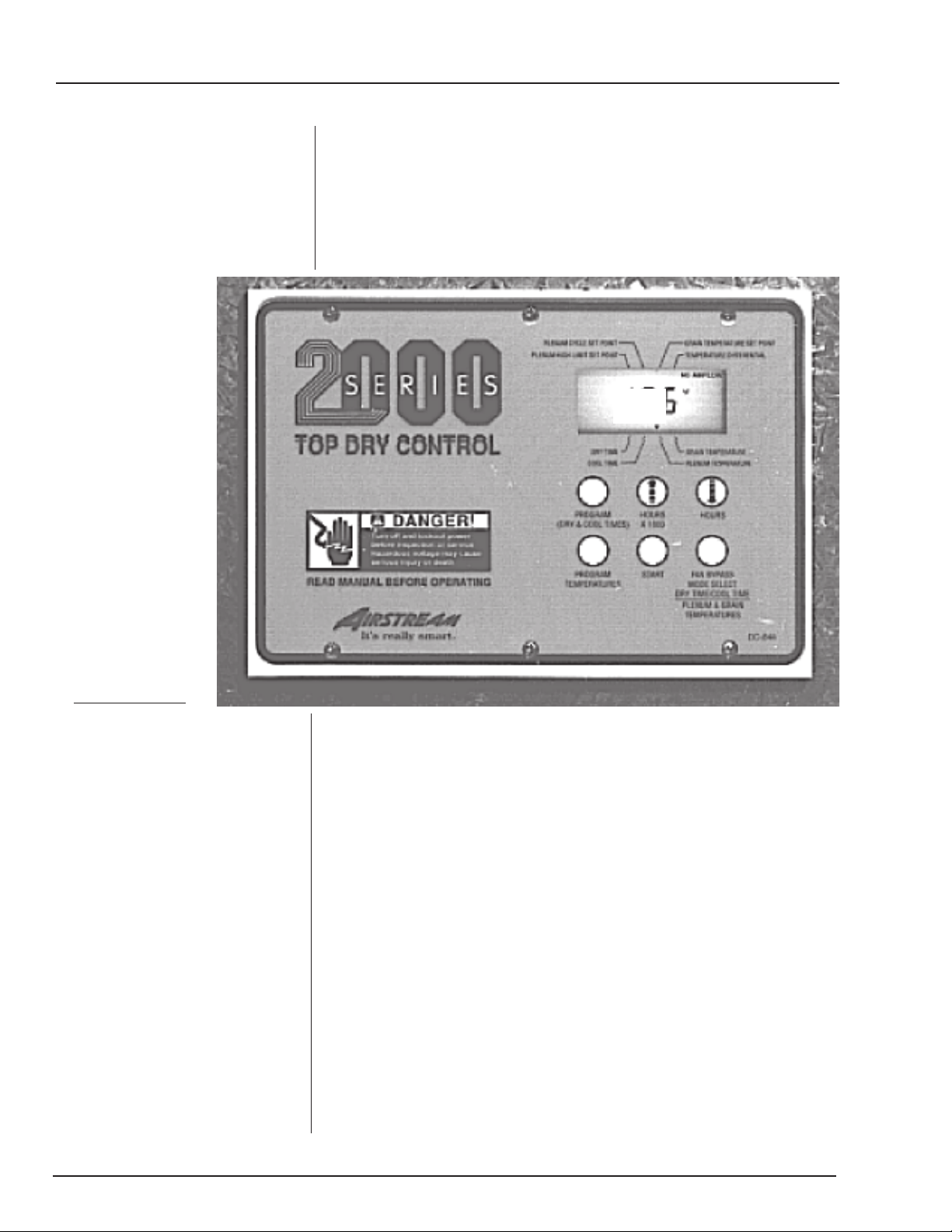
4. Push "PROGRAM (DRY/COOL TIMES)" but
ton on the series 2000 control panel to enter pro-
gram mode. Arrow should be flashing at lower
left side of screen above "DRY TIME".
5. Set dry time using increase or decrease buttons
as recommended for your grain type and mois-
ture content (see drying rates chart page 20).
6. Push "PROGRAM (DRY/COOL TIMES)" but-
ton to continue to set the cool time. Arrow
should be above "COOL TIME".
7. Set cool time desired by using increase or de-
crease buttons.
8. Push "PROGRAM (DRY/COOL TIMES)" but-
ton to exit programming mode.
9. Push "PROGRAM TEMPERATURES" button
to enter temperature programming mode. Arrow
should be flashing at upper left of screen under
"PLENUM HIGH LIMIT SET POINT".
10. Use the increase or decrease buttons to set ple-
num high limit. High limit should be set 20 de-
grees higher than desired plenum temperature
when drying.
11. Press "PROGRAM TEMPERATURES" button
to continue to set "PLENUM CYCLE SET
POINT".
12. Use the increase or decrease buttons to set ple-
num cycle set point. This is the desired plenum
temperature for normal drying. Use the recom-
mended plenum temperature for your grain type
and moisture content.
13. Press the "PROGRAM TEMPERATURES"
button to continue to set the "GRAIN TEM-
PERATURE SET POINT".
14. Use the increase or decrease buttons to set the
grain temperature set point. On the first batch
20. Monitoring of the plenum, grain temperatures,
dry time and cool times is possible by pressing
the mode select button to alternate between
modes.
21. Immediately after the burner shuts off and the
dryer is in the cool cycle, take note of the cur-
rent grain tempera ture.
22. When the dryer shuts down enter this grain tem-
perature in place of the 140° grain temperature
set point entered earlier.
23. Dump batch.
24. After dumping the batch test the moisture con-
tent of the grain. Average several samples. When
computing moisture content make allowances
for cooling of the grain.
25. If the grain moisture content is lower than de-
sired, lower the dry time by 20% and repeat steps
18-23 again on next batch.
26. If the grain moisture content is higher than de-
sired, increasedry time by 30% and repeat steps
18-23 again on next batch.
27. If the grain moisture content is within the de-
sired range, increase the dry time by 20% on
the next batch. This insures that the burner will
turn off at the proper grain temperature
and allows for a wetter batch.
28. After changing times press the increase and de-
crease buttons at the same time to reset.
the set point should be 140°.
15. Press the "PROGRAM TEMPERATURES"
button to continue to set the "TEMPERATURE
DIFFERENTIAL".
16. Use the increase or decrease buttons to set the
temperature differential. The recommended set
point is 10°.
17. Press the "PROGRAM TEMPERATURES"
button to exit the program mode.
18. Press the increase and decrease buttons at the
same time to reset current settings.
19. Once all times and temperatures have been set
press the start button to begin drying.

12
Series 2000 Top Dry Heater Control
DRYING RATES/SHELLED CORN
Top Dry Batch Series
Fan and heater
unit(s)
10-12 H.P.
36" fan
3.5 million
BTU/HR
10-16 H.P.
36" fan
4.5 million
BTU/HR
10-16 H.P.
42" fan
5.75 million
BTU/HR
20 H.P.
42" fan
6.75 million
BTU/HR
30 H.P.
42" fan
8.75 million
BTU/HR
40 H.P.
42" fan
10.25 million
BTU/HR
*Indicates insufficient burner BTUs.
Estimated at ambiant temperature 45 degrees F, relative humidity 65%.
Use only as a guide, conditions will vary capacities.
1/4 cfm cooling.
27' diameter
2 fan
Batch
time
hours
2.1
3.3
5.3
1.8
2.7
4.5
1.4
2.1
3.5
1.9
3.1
4.8
1.6
2.6
4.0
1.2
2.0
3.1
BU/HR
569
369
225
678
441
269
869
564
343
638
393
252
761
469
301
974
600
386
Plenum
temperature
(fahrenheit)
140
160
180
140
160
180
140
160
180
140
160
180
140
160
180
140
160
180
Moisture
removal
%
5%
10%
15%
5%
10%
15%
5%
10%
15%
5%
10%
15%
5%
10%
15%
5%
10%
15%
5%
10%
15%
5%
10%
15%
5%
10%
15%
5%
10%
15%
5%
10%
15%
5%
10%
15%
5%
10%
15%
5%
10%
15%
5%
10%
15%
5%
10%
15%
5%
10%
15%
5%
10%
15%
18' diameter
1 fan
Batch
time
hours
1.9
3.0
4.8
1.6
2.5
4.0
1.2
2.0
3.2
BU/HR
283
180
112
338
214
134
433
274
171
24' diameter
1 fan
Batch
time
hours
2.8
4.4
7.1
2.4
3.7
6.0
*
*
*
2.5
4.0
6.4
2.1
3.3
5.3
1.6
2.6
4.2
2.1
3.2
5.2
1.7
2.7
4.3
1.3
2.1
3.4
2.0
3.1
5.0
1.7
2.6
4.2
1.3
2.1
3.3
BU/HR
356
226
141
425
269
168
*
*
*
398
252
157
474
300
187
607
384
240
486
308
192
580
367
230
742
470
294
504
319
199
602
381
238
770
487
305
27' diameter
1 fan
Batch
time
hours
3.1
4.9
7.9
2.6
4.1
6.6
*
*
*
2.7
4.2
6.8
2.2
3.6
5.7
*
*
*
2.2
3.5
5.6
1.9
2.9
4.7
1.4
2.3
3.7
2.1
3.4
5.4
1.8
2.8
4.5
1.4
2.2
3.5
2.0
3.1
5.0
1.7
2.6
4.2
1.3
2.1
3.3
1.7
2.8
4.4
1.5
2.3
3.7
1.1
1.8
2.9
BU/HR
385
244
152
460
291
182
*
*
*
448
284
177
534
338
211
*
*
*
543
344
214
648
410
256
829
525
328
562
356
222
671
425
266
859
544
340
602
381
238
718
455
284
919
582
363
686
434
271
819
519
324
1,048
664
414
21' diameter
1 fan
Batch
time
hours
2.3
3.6
5.9
1.9
3.1
4.9
1.5
2.4
3.8
2.1
3.3
5.2
1.7
2.7
4.4
1.4
2.1
3.4
BU/HR
321
203
126
382
242
151
490
310
194
357
226
141
426
270
168
545
345
215

13
Series 2000 Top Dry Heater Control DRYING RATES/SHELLED CORN
Top Dry Batch Series
Fan and heater
unit(s)
10-12 H.P.
36" fan
3.5 million
BTU/HR
10-16 H.P.
36" fan
4.5 million
BTU/HR
10-16 H.P.
42" fan
5.75 million
BTU/HR
20 H.P.
42" fan
6.75 million
BTU/HR
30 H.P.
42" fan
8.75 million
BTU/HR
40 H.P.
42" fan
10.25 million
BTU/HR
*Indicates insufficient burner BTUs.
Estimated at ambiant temperature 45 degrees F, relative humidity 65%.
Use only as a guide, conditions will vary capacities.
1/4 cfm cooling.
Plenum
temperature
(fahrenheit)
140
160
180
140
160
180
140
160
180
140
160
180
140
160
180
140
160
180
Moisture
removal
%
5%
10%
15%
5%
10%
15%
5%
10%
15%
5%
10%
15%
5%
10%
15%
5%
10%
15%
5%
10%
15%
5%
10%
15%
5%
10%
15%
5%
10%
15%
5%
10%
15%
5%
10%
15%
5%
10%
15%
5%
10%
15%
5%
10%
15%
5%
10%
15%
5%
10%
15%
5%
10%
15%
30' diameter
1 fan
Batch
time
hours
3.8
6.0
9.5
3.2
4.9
8.0
*
*
*
3.3
5.1
8.2
2.8
4.4
6.8
*
*
*
2.7
4.2
6.7
2.2
3.5
5.6
1.8
2.7
4.4
2.5
3.9
6.4
2.1
3.3
5.3
1.6
2.6
4.1
2.4
3.6
5.9
2.0
3.1
4.9
1.5
2.4
3.9
2.1
3.3
5.2
1.8
2.7
4.4
1.4
2.1
3.4
BU/HR
396
251
157
473
299
187
*
*
*
461
292
182
550
348
218
*
*
*
562
356
222
670
425
265
858
543
339
599
379
237
715
453
283
915
580
362
638
405
253
762
482
302
975
618
386
726
460
287
867
549
343
1,110
702
439
30' diameter
2 fan
Batch
time
hours
2.4
3.8
6.0
2.0
3.2
5.1
1.5
2.5
3.9
1.9
3.3
5.2
1.8
2.7
4.4
1.4
2.1
3.4
BU/HR
629
398
249
751
475
297
961
609
380
728
461
288
869
550
344
1,112
704
440
36' diameter
1 fan
Batch
time
hours
4.1
6.5
10.4
3.4
5.4
8.7
*
*
*
3.3
5.2
8.4
2.8
4.4
7.1
*
*
*
3.2
5.1
8.0
2.7
4.2
6.7
*
*
*
2.9
4.7
7.5
2.5
4.0
6.4
2.0
3.1
4.9
2.7
4.2
6.7
2.2
3.5
5.6
1.8
2.7
4.4
BU/HR
521
330
206
622
394
246
*
*
*
650
411
257
775
491
306
*
*
*
674
427
267
805
510
318
*
*
*
717
454
284
856
542
338
1,095
694
433
810
513
320
966
612
382
1,236
783
489
36' diameter
2 fan
Batch
time
hours
2.9
4.6
7.3
2.5
3.9
6.1
*
*
*
2.6
4.0
6.5
2.1
3.4
5.4
1.6
2.7
4.2
2.1
3.3
5.3
1.8
2.8
4.5
1.4
2.2
3.5
2.0
3.2
5.2
1.8
2.7
4.4
1.3
2.1
3.4
1.9
2.9
4.7
1.5
2.5
4.0
1.3
2.0
3.2
BU/HR
741
469
293
884
560
350
*
*
*
841
533
333
1,004
636
397
1,284
814
508
1,022
647
404
1,219
772
482
1,560
988
617
1,058
670
418
1,262
799
499
1,615
1,023
639
1,142
723
452
1,363
863
539
1,744
1,105
690

14
Series 2000 Top Dry Heater Control
FACTORY CONFIGURATION
Configuration Dip
Switches (Normally Done
At Gsi)
Top Dry remote
display at the bot-
tom-dip switch 1 &
6 on/all others off.
Top Dry master
with a remote dis-
play at the bottom-
dip switch 6 & 7 on/
all others off.
These switches are used to con-
figure the heater control for vari-
ous types of heaters.
Top Dry 2nd fan
heater-dip switch 2
& 6 on/all others off.
Top Dry 3rd fan
heater-dip switch 1,
2 & 6 on/all others
off.
Top Dry master
with a remote dis-
play at the bottom
and 2 slave fan
heater-dip switch 6,
7 & 8 on/all others
off.
Top Dry master
with a remote dis-
play at the bottom
and one slave fan
heater-dip switch 6
& 8 on/all others off.
Multiple heaters connected to-
gether through the serial link.
Top Dry stand
alone with no re-
mote display at the
bottom-dip switch 6
on/all others off.
The backside of the control board, showing the dip switch placement.

15
Series 2000 Top Dry Heater Control ERROR CONDITIONS
symbols will be flashing. If a limit switch error or
one of the error numbers 1 through 8 occurs, that
error is displayed on the slave where the error origi-
nates. The master displays "SLA ERROR".Two or more heaters may be connected together
Multiple Heater Error Conditions
Limit Switches
78 9 10 11 12
Illegal flame
sense
Error 7 is
most likely
caused by stuck
open solenoid.
Error 7 will not
shut down fan
until loss of
flame is detected
by control.
Flame probe
short error
Slave #1 incon-
sistent with mas-
ter with either
the drying grain
flag or the LP
main solenoid or
cycle solenoid-
most likely the
slave got reset
powering up with
the solenoids off
Slave #2
inconsistent
same as error 9
for slave #1
Slave #3
inconsistent
same as error 9
for slave #1
Wrong voltage.
Dip switch #5 is
the voltage se-
lector switch. If
dip switch #5 in
"ON" that se-
lects 240 VAC.
If the unit has
only 120 VAC
applied, error 12
will show up. If
dip switch #5
is"OFF" that se-
lects 120 VAC. If
the unit has 240
VAC applied er-
ror 12 will show
up.
This is im-
portant because
if the fan heater
is set up at GSI
for 120 VAC and
the customer
connects to 240
VAC the heater
control will work,
but if allowed to
operate the so-
lenoids will have
240 VAC applied
to them which
will damage so-
lenoids.
1 2 3 4 5 6
Plenum tem-
perature probe 1
open
Plenum tem-
perature probe 1
short
Grain tempera-
ture probe 2
open
Grain tempera-
ture probe 2
short
Airflow open Airflow short
MISC ERROR NUMBERS
The following limit switch errors light up indi-
vidually on the heaters LCD screen:
PLENUM, HOUSING, VAPOR, TEMP HI
LIMIT
(Errors 9 through 11 are displayed only if multiple heat-
ers are tied together through serial link).
Note: Temperature sensor connection-the temperature
sensor (bolt) must always be connected to the master.
In the case of the Top Dry, both temperature sensors
must be connected to the master (unit at the top). Top
Dry grain temperature input is connected to J7 pins 14
and 18.
through the serial link. If the master cannot com-
municate with a slave controller, the master will dis-
play "SLA" on the main display and the "RX" "TX"

WARRANTY
EXCEPT FOR THE ABOVE STATED EXPRESS LIMITED WARRANTIES, GSI MAKES NO WARRANTY
OF ANY KIND, EXPRESSED OR IMPLIED, INCLUDING, WITHOUT LIMITATION, WARRANTIES
OF MERCHANTABILITY OR FITNESS FOR A PARTICULAR PURPOSE OR USE IN CONNECTION
WITH (i) PRODUCT MANUFACTURED OR SOLD BY GSI OR (ii) ANY ADVICE, INSTRUCTION,
RECOMMENDATION OR SUGGESTION PROVIDED BYAN AGENT, REPRESENTATIVE OR EMPLOYEE
OF GSI REGARDING OR RELATED TO THE CONFIGURATION, INSTALLATION, LAYOUT, SUIT-
ABILITY FOR A PARTICULAR PURPOSE, OR DESIGN OF SUCH PRODUCT OR PRODUCTS.
IN NO EVENT SHALL GSI BE LIABLE FOR ANY DIRECT, INDIRECT, INCIDENTAL OR CONSE-
QUENTIAL DAMAGES, INCLUDING, WITHOUT LIMITATION, LOSS OF ANTICIPATED PROFITS
OR BENEFITS. PURCHASER'S SOLE AND EXCLUSIVE REMEDY SHALL BE LIMITED TO THAT
STATED ABOVE, WHICH SHALL NOT EXCEED THE AMOUNT PAID FOR THE PRODUCT PUR-
CHASED. THIS WARRANTY IS NOT TRANSFERABLE AND APPLIES ONLY TO THE ORIGINAL
PURCHASER. GSI SHALL HAVE NO OBLIGATION OR RESPONSIBILITY FOR ANY REPRESENTA-
TIVE OR WARRANTIES MADE BY OR ON BEHALF OF ANY DEALER, AGENT OR DISTRIBUTOR
OF GSI.
GSI ASSUMES NO RESPONSIBILITY FOR FIELD MODIFICATIONS OR ERECTION DEFECTS
WHICH CREATE STRUCTURAL OR STORAGE QUALITY PROBLEMS. MODIFICATIONS TO THE
PRODUCT NOT SPECIFICALLY COVERED BY THE CONTENTS OF THIS MANUAL WILL NUL-
LIFY ANY PRODUCT WARRANTY THAT MIGHT HAVE BEEN OTHERWISE AVAILABLE.
THE FOREGOING WARRANTY SHALL NOT COVER PRODUCTS OR PARTS WHICH HAVE BEEN
DAMAGED BY NEGLIGENT USE, MISUSE, ALTERATION OR ACCIDENT. THIS WARRANTY COV-
ERS ONLY PRODUCTS MANUFACTURED BY GSI. THIS WARRANTY IS EXCLUSIVE AND IN LIEU
OF ALL OTHER WARRANTIES EXPRESS OR IMPLIED. GSI RESERVES THE RIGHT TO MAKE
DESIGN OR SPECIFICATION CHANGES AT ANY TIME.
PRIOR TO INSTALLATION, PURCHASER HAS THE RESPONSIBILITY TO RESEARCH AND COM-
PLY WITH ALL FEDERAL, STATE AND LOCAL CODES WHICH MAY APPLY TO THE LOCATION
AND INSTALLATION.
THE GSI GROUP, INC. ("GSI") WARRANTS ALL PRODUCTS MANUFACTURED BY GSI TO BE FREE
OF DEFECTS IN MATERIAL AND WORKMANSHIP UNDER NORMAL USAGE AND CONDITIONS
FOR A PERIOD OF 12 MONTHS AFTER RETAIL SALE TO THE ORIGINAL END USER OF SUCH
PRODUCTS. GSI'S ONLY OBLIGATION IS, AND PURCHASER'S SOLE REMEDY SHALL BE FOR
GSI, TO REPAIR OR REPLACE, AT GSI'S OPTION AND EXPENSE, PRODUCTS THAT, IN GSI'S SOLE
JUDGMENT, CONTAIN A MATERIAL DEFECT DUE TO MATERIALS OR WORKMANSHIP. ALL
DELIVERY AND SHIPMENT CHARGES TO AND FROM GSI'S FACTORY WILL BE PURCHASER'S
RESPONSIBILITY. EXPENSES INCURRED BY OR ON BEHALF OF THE PURCHASER WITHOUT
PRIOR WRITTEN AUTHORIZATION FROM AN AUTHORIZED EMPLOYEE OF GSI SHALL BE THE
SOLE RESPONSIBILITY OF THE PURCHASER.

This Equipment shall be installed in accordance
with the current installation codes and applicable
regulations which should be carefully followed in
all cases. Authorities having jurisdiction should be
consulted before installation occurs.
Copyright © 2005 by The GSI Group
Printed in the USA
The GSI Group, Inc.
1004 E. Illinois St.
Assumption, IL 62510-0020
Phone: 217-226-4421
Fax: 217-226-4420
e-mail: [email protected]
internet: http://www.grainsystems.com
Other manuals for 2000 Series
4
Table of contents
Other GSi Industrial Equipment manuals

GSi
GSi PNEG-728 Instruction Manual

GSi
GSi TopDry Autoflow 36 FT DIAMETER Instructions for use

GSi
GSi PNEG-1859 Instructions for use

GSi
GSi RSG1212GM-X21 User manual

GSi
GSi 40 Series Instructions for use

GSi
GSi PNEG-1829 User manual

GSi
GSi PNEG-1831 User manual

GSi
GSi PNEG-1393 User manual

GSi
GSi 40 Series Instructions for use

GSi
GSi TopDry User manual