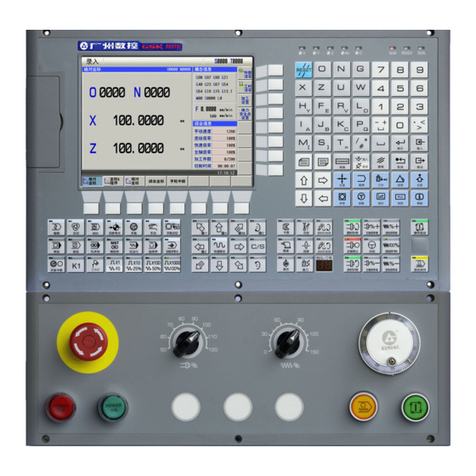
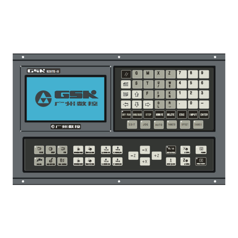
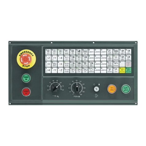
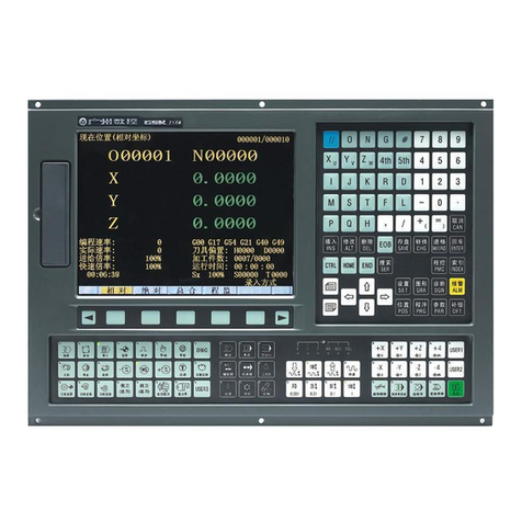
GSK983Ma-H/V Milling CNC System Connection Manual
III
Contents
Precautions .................................................................................................................................. 1
1. NC Unit Interfaces.................................................................................................................... 3
2. Interconnect Block Diagram ..................................................................................................... 4
3. Connection between NC Unit and DA98D Drive Unit (without Brake) ................................... 5
4. Connection between NC Unit and DA98D Drive Unit (Z Axis with Brake) ............................. 6
5. Connection between NC Unit and Spindle Servo Drive Unit .................................................... 7
6. Connection between NC Unit and Spindle Inverter .................................................................. 8
7. Connection between NC Unit and I/O Unit............................................................................... 9
8. Machine Tool Panel Interfaces ............................................................................................... 10
9. Connection between NC Unit and Operation Panel ............................................................... 11
10. Connection between External MPG and Operation Panel ................................................... 12
11. Connection between NC Unit and PC .................................................................................. 13
12. Connection Method for Z Axis Brake and System Power-on Control ................................... 14
13. General of External I/O Unit (X1) Interfaces......................................................................... 15
14. Connectivity Diagrams for I/O Unit (X1) Input/Output Signals.............................................. 16
15. I/O Points Definition (X1)...................................................................................................... 17
16. Instructions for Installing Mechanical Position Detection Switch for Spindle Orientation...... 20
17. Instruction for installing mechanical position detection switch at Z axis 2nd reference point 21
Appendix. Installation Dimension Drawings ............................................................................... 22
GSK983Ma-H/V Milling CNC System Connection Manual Version Upgrading Records ............ 27


