manuals.online logo
Brands
  1. Home
  2. •
  3. Brands
  4. •
  5. GSK
  6. •
  7. Control System
  8. •
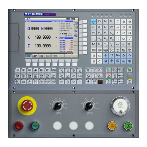
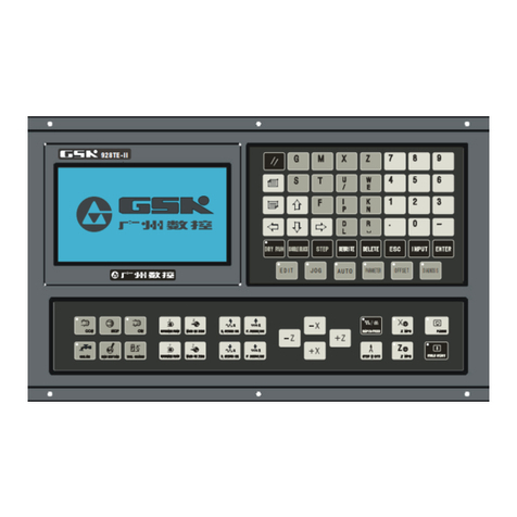
  9. GSK GSK928TE User manual

GSK GSK928TE User manual

GSK928TE/GSK928TC
Turning Machine CNC System
User Manual
GSK928TE/GSK928TC CNC System User Manual
i
Preface
Thank you for purchasing GSK928TE/GSK928TC CNC system. For optimum performance
and safety, please read this manual carefully.
Caution: Improper operation leads to accidents. Before operating the system, please
read the manual completely.
Before Use:
zConnect the emergency stop button of the system firmly and correctly, otherwise an
emergency stop alarm will occur when switch on the system, so that the system cannot
work properly.
zSet the reference point of the program of the system according to the actual mounting
position of the tool of the machine that the system controls.
The manual is applied to software V3.20 of GSK928TE/GSK928TC CNC system. Read
Appendix 3, Appendix 4, and Appendix 5 when using V2.13, V2.23, V3.01 software of
GSK928TC CNC system. For convenience, the manual does not distinguish 928TE from
928TC.
Chinese version of all technical documents in Chinese and English languages is
regarded as final.
GSK928TE/GSK928TC CNC System User Manual
ii
Suggestions for Safety
For the safety of the system, the operator who operates the system, and the machine, these
suggestions must be read before installing and operating the system.
Safety instructions indicated in the manual must be followed when operating the system. Do
not operate it until the manual is read completely.
Follow safety instructions for the machine that the system will control. Do not run the
machine until you have completely read both the instructions and this manual.
GSK928TE/GSK928TC CNC System User Manual
iii
Graphic symbol
Caution Operation against the instructions may cause the operator serious injuries.
Alarm Wrong operation may injure the operator and damage the system.
Warning Improper operation may result in damage to the machine, as well its products.
Important information
Shield
Earthing (PE)
Encoder
Coil of contact or relay
Exchange
Connecting terminal
GSK928TE/GSK928TC CNC System User Manual
iv
Notice
1. Check before acceptance
Warning Inspect the packing box, where the system is kept, for external damages.
2. Delivery and storage
Warning Moistureproof measures are needed while the system is delivered and
stored. Never climb the packing box, neither stand on it, nor place heavy
items on it. Do not put many packing boxes in piles. Take particular care of
the front panel and the display of the system.
3. Installation
Warning Protect the system from sunlight and raindrops. The shell of the system is not
waterproof.
Warning Prevent dust, corrosive air, liquid, conductors and inflammable substances
from entering the system.
Keep the system away from inflammable and explosive substances. Avoid
places where there is powerful electromagnetic interference.
Install the system firmly, without vibration.
4. Connection
Caution Only qualified persons can connect the system or check the connection. No
damage to the connecting wires. Do not press or open the cover of the system
with power on.
Caution The voltage and the polarity of connecting plugs must accord with the manual.
Wet hands are dangerous to grasp the plug or the switch.
Warning The connection must be proper and firm.
The system must be earthed.
5. Debugging
Warning Make sure that the parameters of the system is correct before running.
No parameter is beyond the setting limit in the manual.
6. Operation
Caution Only qualified operators can operate the system.
GSK928TE/GSK928TC CNC System User Manual
v
Ensure the switch is OFF before connecting the power supply.
Warning The operator can not leave the system to work alone.
Do not switch on the system until making sure the connection is correct.
The emergency stop button is able to disconnect all power supplies when
the system breaks down. Do not switch on/off the system frequently.
Warning Prevent the system from environmental interference.
7. Troubleshooting
Caution Unqualified persons cannot repair the system.
Warning After alarms, do not restart the system until the breakdown is fixed.
GSK928TE/GSK928TC CNC System User Manual
vi
Safety suggestions for programming
1. Coordinate system
Incorrect coordinate system may cause the machine not to work as expected even if the
program is correct, which may injure the operator, and damage the machine as well as its
tool and workpiece.
2. G00 rapid traverse
G00 rapid traverse performs nonlinear motion between its starting point and end point.
Make sure that the path for the tool is safe before G00 rapid traverse starts, otherwise the
tool, the machine and the workpiece may be damaged, and even the operator injured.
3. The manual introduces in detail all functions of the system, including optional functions
and max. controllable ranges, which are subject to change with the machine. If there is
any doubt, please read the instruction for the machine.
4. CNC machines depend on CNC systems, but also power voltage cabinets, servo
systems, CNC and the operator panels. It is hard to explain all the integrated functions,
programming and operation. Do not use integrated instructions not included in the
manual until they have been tested successfully.
GSK928TE/GSK928TC CNC System User Manual
vii
Safety suggestions for operation
1. Test the machine without workpieces or tools. Make sure that the machine runs well
before it starts to work.
2. Check the input data of the system carefully before operating the machine. Incorrect
input data may cause the machine to work improperly, so as to damage the workpiece
and the tool, as well injure the operator.
3. Make sure that the input feedrate of the system is suitable for the expected operation.
Feedrate has a maximum for each machine, and the amount of the feed rate is subject to
change with operation. Choose the maximum according to the instructions of the
machine. Improper feedrate leads the machine to work wrongly, so as to damage the
workpiece and the tool, as well injuretheoperator.
4. When tool compensation is needed, check the direction and the amount of the
compensation. Improper compensation causes the machine to work wrongly, so as to
damage the workpiece and the tool, as well injure the operator.
5. If the machine is to run in Manual Mode, check the current position of the tool and the
workpiece, and correctly specify the moving axis, moving direction and the feedrate.
Handwheel control with great override, such as 100, may damage the machine and its
tool, even injure the operator.
6. If the tool is return to the reference point, make sure that the machine has been equipped
with the device to detect the reference point, otherwise, the tool can not reach the
reference point, which may damage the machine and its tool, and even injure the
operator.
GSK928TE/TC CNC System User Manual
1
Content
Operation
1. Overview.....................................................................................................................1
2. Technical specification ............................................................................................. 2
3. Operation panel ......................................................................................................... 3
4. Operation.................................................................................................................. 10
4.1 System power on/power off ................................................................................................10
4.2 CNC system operating mode.............................................................................................. 11
4.3 Edit mode............................................................................................................................13
4.4 Jog mode ............................................................................................................................29
4.5 Auto mode .....................................................................................................................53
4.6 Parameter setting................................................................................................................68
4.7 Tool offset setting mode......................................................................................................80
4.8 Diagnosis ............................................................................................................................84
4.9 Alarm of emergency stop and overtravel............................................................................88
4.10 LCD brightness adjust.......................................................................................................90
4.11 Driver switch control..........................................................................................................90
Programming
1. Overview................................................................................................................ 91
1.1 Coordinate axis and its direction.........................................................................................91
1.2 Machine zero.......................................................................................................................92
1.3 Programming coordinate.....................................................................................................92
1.4 Workpiece coordinate system.............................................................................................93
1.5 Reference point...................................................................................................................94
2. Program structure ................................................................................................ 94
2.1 Character ............................................................................................................................94
2.2 Word....................................................................................................................................96
2.3 Block number......................................................................................................................96
2.4 Block ...................................................................................................................................96
2.5 Program structure ...............................................................................................................97
3. Codes and their functions ................................................................................... 97
3.1 Gcodes — preparatory function ...............................................................................97
3.2 M function — auxiliary function ..............................................................................102
3.3 S function — spindle function ...................................................................................108
3.4 T function — tool function .........................................................................................109
3.5 F function — feedrate function.................................................................................. 110
GSK928TE/TC CNC System User Manual
2
4. Programming rules..............................................................................................110
4.1 Some codes in one block...................................................................................................111
4.2 Modal and initial state of code ...........................................................................................111
4.3 Other rules .........................................................................................................................111
4.4 Programming example...................................................................................................... 112
4.5 Alarm list............................................................................................................................122
Appendix 1:GSKTR communication program specification............................... 124
Appendix 2:GSK928TE CNC System software version specification ................ 126
Appendix 3:GSK928TE CNC System V2.13 software specification.................... 127
Appendix 4:V2.23 version of GSK928TE CNC System specification................. 129
Appendix 5:V3.12 version software of GSK928TE CNC System specification.. 130
Appendix 6:V3.20 FLASH chip copy and verification.......................................... 131
Connection
1. Interface overview ................................................................................................. 132
1.1 Interface layout .................................................................................................................132
1.2 Total frame ........................................................................................................................133
1.3 Total connection graph......................................................................................................134
2. Interface function................................................................................................... 135
2.1 Specification......................................................................................................................135
2.2 Interface graph..................................................................................................................136
3. CNC device connection......................................................................................... 137
3.1 X1 communication interface..............................................................................................137
3.3 X3 spindle encoder interface ............................................................................................140
3.4 X4 toolpost interface.........................................................................................................142
3.5 X5 feed driver interface.....................................................................................................144
3.6 X6 switching value input interface ....................................................................................155
3.7 X7 switching value output.................................................................................................158
3.8 X7 spindle inverter interface .............................................................................................161
Appendix 1 Toolpost controller circuit diagram..................................................... 162
Appendix 2 Interface circuit diagram....................................................................... 164
Appendix 3 Machine zero return mode................................................................. 166
Appendix 4 External control connection graph................................................... 168
Appendix 5 GSK928TE CNC integrated wiring diagram........................................ 169
Appendix 6 GSK928TE CNC contour and installation diagram............................. 171

Other manuals for GSK928TE

1

This manual suits for next models

1

Other GSK Control System manuals

GSK GSK983Ma User manual

GSK

GSK GSK983Ma User manual

GSK GSK928TEa User manual

GSK

GSK GSK928TEa User manual

GSK GSK983Ta-H Instruction manual

GSK

GSK GSK983Ta-H Instruction manual

GSK 980TDi User manual

GSK

GSK 980TDi User manual

GSK GSK980TDc User manual

GSK

GSK GSK980TDc User manual

GSK GSK928TE User manual

GSK

GSK GSK928TE User manual

GSK 218M Instruction manual

GSK

GSK 218M Instruction manual

GSK 988T User manual

GSK

GSK 988T User manual

GSK 983Ma-V Instruction manual

GSK

GSK 983Ma-V Instruction manual

GSK GSK983M-H User manual

GSK

GSK GSK983M-H User manual

GSK GSK988TA User manual

GSK

GSK GSK988TA User manual

GSK GSK218MC User manual

GSK

GSK GSK218MC User manual

Popular Control System manuals by other brands

Norac SPRA-COUPE 7000 Series installation manual

Norac

Norac SPRA-COUPE 7000 Series installation manual

PROMETHEUS MR-20 Operator's guide

PROMETHEUS

PROMETHEUS MR-20 Operator's guide

Aybey Elektronik AE-MAESTRO installation manual

Aybey Elektronik

Aybey Elektronik AE-MAESTRO installation manual

Ormazabal cgmcosmos-l General instructions

Ormazabal

Ormazabal cgmcosmos-l General instructions

SMART Showmation Installation and service manual

SMART

SMART Showmation Installation and service manual

BFT XPASS B 800C Installation and user manual

BFT

BFT XPASS B 800C Installation and user manual

Hydronix Hydro-Control HC07 Operation manual

Hydronix

Hydronix Hydro-Control HC07 Operation manual

HEIDENHAIN LIP 471R Mounting instructions

HEIDENHAIN

HEIDENHAIN LIP 471R Mounting instructions

Steril-Aire ESE 1 Series Installation and operation instructions

Steril-Aire

Steril-Aire ESE 1 Series Installation and operation instructions

Smartwares SHS-53000 user manual

Smartwares

Smartwares SHS-53000 user manual

NPI EPMS-07 Operating instructions and system description

NPI

NPI EPMS-07 Operating instructions and system description

WAGO WAGO-I/O-SYSTEM 750-476 manual

WAGO

WAGO WAGO-I/O-SYSTEM 750-476 manual

Intermatic RC2163E Installation, operation & service manual

Intermatic

Intermatic RC2163E Installation, operation & service manual

Lennox Harmony III Homeowner's manual

Lennox

Lennox Harmony III Homeowner's manual

Emec DIN DIGITAL CD operating manual

Emec

Emec DIN DIGITAL CD operating manual

OPTO 22 B3000-B user guide

OPTO 22

OPTO 22 B3000-B user guide

Mercury Premier Dual Handle ERC quick reference

Mercury

Mercury Premier Dual Handle ERC quick reference

Grundfos PC Tool CU 300 Installation and operating instructions

Grundfos

Grundfos PC Tool CU 300 Installation and operating instructions

manuals.online logo
manuals.online logoBrands
  • About & Mission
  • Contact us
  • Privacy Policy
  • Terms and Conditions

Copyright 2025 Manuals.Online. All Rights Reserved.