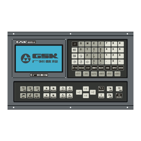
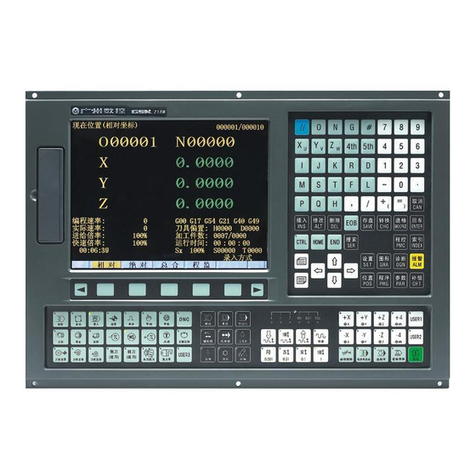
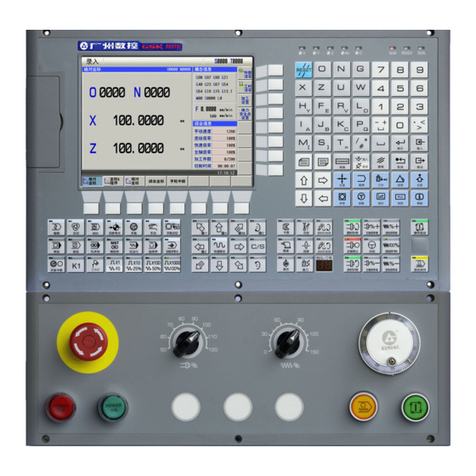
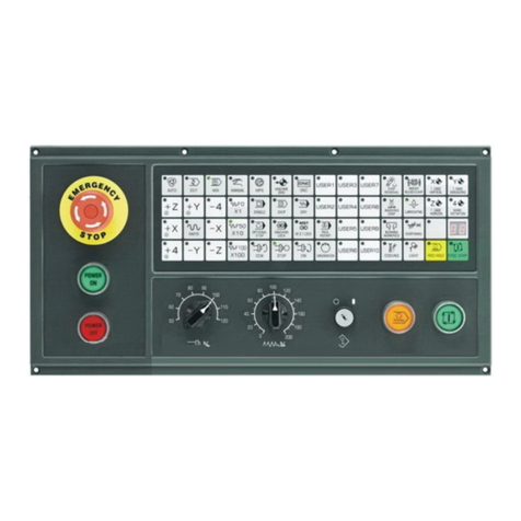
GSK GSK988TA User manual

I
In this user manual we have tried to describe the matters
concerning the operation of this CNC system to the greatest extent.
However, it is impossible to give particular descriptions for all
unnecessary or unallowable operations due to length limitation and
products application conditions;Therefore, the items not presented
herein should be regarded as “impossible” or “unallowable”.
Copyright is reserved to GSK CNC Equipment Co., Ltd. It is
illegal for any organization or individual to publish or reprint this manual.
GSK CNC Equipment Co., Ltd. reserves the right to ascertain their
legal liability.

GSK988TA/GSK988TA1/GSK988TB Turning Center CNC System User Manual【Programming & Operation】
II
Preface
Your Excellency,
We are honored by your purchase of this GSK988TA/988TA1/988TB
Turning CNC System made by GSK CNC Equipment Co., Ltd.
This book describes GSK988TA/988TA1/988TB Turning Center CNC
System, Programming and Operation (software version: V1.12), and
concretely introduces the programming and operations.
To ensure safe and effective running, please read this manual
carefully before installation and operation.
Warning
Accident may occur by improper connection and operation!
This system can only be operated by authorized and qualified personnel.
Special caution:
The power supply fixed on/in the cabinet is exclusively used
for the CNC system made by GSK.
It can't be applied to other purposes, or else it may cause
serious danger!

Notes
III
Cautions
■Delivery and storage
●Packing box over 6 layers in pile is unallowed.
●Never climb the packing box, stand on it or place heavy objects on it.
●Do not move or drag the products by the cables connected to it.
●Forbid collision or scratch to the panel and display screen.
●Avoid dampness, insolation and drenching.
■Open-package inspection
●Confirm that the products are the required ones.
●Check whether the products are damaged in transit.
●Confirm that the parts in packing box are in accordance with the packing list.
●Contact us in time if any inconsistence, shortage or damage is found.
■Connection
●Only qualified personnel can connect the system or check the connection.
●The system must be earthed, and the earth resistance must be less than 0.1Ω.
The earth wire cannot be replaced by zero wire.
●The connection must be correct and firm to avoid any fault or unexpected
consequence.
●Connect with surge diode in the specified direction to avoid damage to the
system.
●Switch off power supply before plugging out or opening electric cabinet.
■Troubleshooting
●Switch off power supply before troubleshooting or changing components.
●Check the fault when short circuit or overload occurs. Restart can only be done
after troubleshooting.
●Frequent switching on/off of the power is forbidden, and the interval time should
be at least 1 min.

GSK988TA/GSK988TA1/GSK988TB Turning Center CNC System User Manual【Programming & Operation】
IV
All specifications and designs herein are subject to change without notice.
Warning
zBefore installing, connecting, programming and operating, please carefully read
the product user manual and the manual from the machine tool manufacturer and
strictly operate accordance with the regulations in the manual; otherwise, the
product or the machine tool may be damaged, the workpiece may get rejected,
even the personal injury may occur.
Announcement
zThis manual describes various possibilities as much as possible. However,
operations allowable or unallowable cannot be explained one by one due to so
many possibilities that may involve with, so the contents that are not specially
stated in this manual shall be considered as unallowable.
Caution
zFunctions, technical indexes (such as precision and speed) described in this user
manual are only for this system. Actual function deployment and technical
performance of the machine tool are designed by the machine tool manufacturer,
so function configuration and technical indexes are subject to the user manual
from the machine tool manufacturer.
Refer to the user manual from the machine tool manufacturer for function and
meaning of each button on the machine panel.

Notes
V
Safety Responsibility
Manufacturer’s Responsibility
——Be responsible for the danger which should be eliminated and/or controlled on
design and configuration of the provided CNC systems and accessories.
——Be responsible for the safety of the provided CNC systems and accessories.
——Be responsible for the provided message and advice for the users.
User’s Responsibility
——Be responsible for being familiar with and mastering the safety operation
procedures through training with the safety operation of the CNC system.
——Be responsible for the dangers caused by adding, changing or altering the original
CNC systems and the accessories.
——Be responsible for the dangers caused by failing to observe the provisions in the
manual for operation, adjustment, maintenance, installation and storage.
This manual is kept by the end user.
Thank you for supporting us in the use of GSK’s products!

GSK988TA/GSK988TA1/GSK988TB Turning Center CNC System User Manual【Programming & Operation】
VI

Contents
VII
Contents
Programming
Chapter 1 Programming Fundamental ................................................................3
1.1 Product Introduction...........................................................................................................3
1.2 CNC System of Machine Tools and CNC Machine Tools ..............................................6
1.3 Programming Fundamentals .............................................................................................7
1.3.1 Coordinates Definition .......................................................................................................................... 7
1.3.2 Increment System ................................................................................................................................. 8
1.3.3 Max. Travel............................................................................................................................................. 9
1.3.4 Reference Point................................................................................................................................... 10
1.3.5 Machine Coordinate System ............................................................................................................. 10
1.3.6 Workpice Coordinate System............................................................................................................ 10
1.3.7 Local Coordinate System................................................................................................................... 10
1.3.8 Interpolation Function ......................................................................................................................... 11
1.4 Coordinate Value and Dimension ...................................................................................12
1.4.1 Absolute Programming and Incremental Programming ................................................................ 12
1.4.2 Diameter Programming and Radius Programming ........................................................................ 13
1.4.3 Decimal Programming........................................................................................................................ 14
1.4.4 Conversion between the Metric and the Inch.................................................................................. 15
1.4.5 Linear Axis and Rotary Axis............................................................................................................... 15
1.5 Structure of an NC Program ............................................................................................15
1.5.1 Program Name .................................................................................................................................... 17
1.5.2 Block Format........................................................................................................................................ 17
1.5.3 Word...................................................................................................................................................... 18
1.5.4 Block Number ...................................................................................................................................... 27
1.6 Program Run ...................................................................................................................... 27
1.6.1 Sequence of Program Run ................................................................................................................ 27
1.6.2 Execution Sequence of Word............................................................................................................ 28
Chapter 2 G Codes....................................................................................................29
2.1 Summary.............................................................................................................................29

GSK988TA/GSK988TA1/GSK988TB Turning Center CNC System User Manual【Programming & Operation】
VIII
2.1.1 G code Classification.......................................................................................................................... 29
2.1.2 Omitting Word Input............................................................................................................................ 32
2.1.3 Relevant Definitions............................................................................................................................ 33
2.2 Rapid Traverse (Positioning) G00................................................................................... 33
2.3 Linear Interpolation G01................................................................................................... 34
2.4 Circular Interpolation G02, G03....................................................................................... 35
2.5 Spiral Interpolation G02, G03 .......................................................................................... 38
2.6 Dwell G04............................................................................................................................ 40
2.7 Cylindrical Interpolation 7.1............................................................................................. 41
2.8 Programmable Parameter Input G10.............................................................................. 45
2.8.1 Workpiece Coordinate System Offset.............................................................................................. 45
2.8.2 Setting a Workpiece Coordinate System’s Offset Amount............................................................ 46
2.8.3 Additional Workpiece Coordinate System Setting ......................................................................... 47
2.8.4 Automatically Inputting a Tool Life.................................................................................................... 47
2.8.5 Setting a Tool Offset Value ................................................................................................................ 48
2.9 Polar Coordinate Interpolation G12.1, G13.1 ................................................................ 49
2.10 Metric/Inch Switch G20, G21 ......................................................................................... 51
2.11 Stored Travel Check G22, G23....................................................................................... 52
2.12 Skip Interpolation G31 .................................................................................................... 53
2.13 Automatic Tool Offset G36, G37.................................................................................... 55
2.14 Reference Point Function .............................................................................................. 57
2.14.1 Reference Point Return G28........................................................................................................... 57
2.14.2 2nd, 3rd, 4th Reference Point Return............................................................................................ 58
2.15 Relevant Functions of Coordinate System ................................................................. 58
2.15.1 Selecting Machine Coordinate System Position G53.................................................................. 59
2.15.2 Workpiece Coordinate System Setting G50 ................................................................................. 60
2.15.3 Workpiece Coordinate System Selection G54~G59.................................................................. 61
2.15.4 Additional Workpiece Coordinate System G54.1......................................................................... 63
2.15.5 Local Coordinate System Setting G52 .......................................................................................... 64
2.16 Plane Selection Code G17~G19................................................................................... 66
2.17 Exact Stop Mode G61/Cutting Mode G64 .................................................................... 66

Contents
IX
2.18 Fixed Cycle Code.............................................................................................................67
2.18.1 Axial Cutting Cycle G90 ................................................................................................................... 67
2.18.2 Radial Cutting Cycle G94 ................................................................................................................ 70
2.19 Multiple Cycle Codes ......................................................................................................73
2.19.1 Axial Roughing Cycle G71............................................................................................................... 73
Monontone change is not observed along the Z axis ................................................1
2.19.2 Radial Roughing Cycle G72............................................................................................................ 80
2.19.3 Closed Cutting Cycle G73 ............................................................................................................... 84
2.19.4 Finishing Cycle G70.......................................................................................................................... 90
2.19.5 Axial Grooving Multiple Cycle G74................................................................................................. 90
2.19.6 Radial Grooving Multiple Cycle G75 .............................................................................................. 94
2.19.7 Notes for Multi Cycle Machining ..................................................................................................... 98
2.20 Threading Cutting............................................................................................................98
2.20.1 Thread Cutting with Constant Lead G32 ....................................................................................... 99
2.20.2 Thread Cutting with Variable Lead G34....................................................................................... 102
2.20.3 Thread Cutting Cycle G92 ............................................................................................................. 103
2.20.4 Multiple Thread Cutting Cycle G76 .............................................................................................. 106
2.21 Constant Surface Speed Control G96, Constant Rotational Speed Control G97
..................................................................................................................................................... 112
2.22 Feedrate per Minute G98/G94, Feedrate per Rev G99/G95 ..................................... 114
2.23 Drilling/Boring Fixed Cycle Code................................................................................ 115
2.23.1 End drilling cycle G83 /side drilling cycle G87............................................................................ 116
2.23.2 End Boring CycleG85 / Side Boring Cycle G89 ......................................................................... 121
2.23.3 Cancelling Drilling/Boring G80 ...................................................................................................... 122
2.23.4 Notes for Drilling/Boring Cycle ...................................................................................................... 123
2.24 Tapping Cycle Code ...................................................................................................... 123
2.24.1 Tapping Mode .................................................................................................................................. 123
2.24.2 End Rigid Tapping Cycle (G84) / Side Rigid Tapping Cycle (G88).......................................... 124
2.24.3 End Common Tapping Cycle G84/Side Common Tapping Cycle G88 ................................... 130
2.25 Automatic Chamfering Function................................................................................. 134
2.26 Function of Directly Inputting Graphic Dimension .................................................. 136
2.27 Macro Code .................................................................................................................... 140
2.27.1 Variable............................................................................................................................................. 140

GSK988TA/GSK988TA1/GSK988TB Turning Center CNC System User Manual【Programming & Operation】
X
2.27.2 System Variable .............................................................................................................................. 142
2.27.3 Operation and Jump Code ............................................................................................................ 146
2.27.4 Macro Program Statement and NC Statement........................................................................... 151
2.27.5 Macro Program Call ....................................................................................................................... 151
2.28 Slant Axis Control ......................................................................................................... 154
2.29 G Code System B .......................................................................................................... 156
2.29.1 Differences of G Codes ................................................................................................................. 156
2.29.2 Absolute Code and Incremental Code G90, G91 ...................................................................... 157
2.29.3 Cycle Code Processing ................................................................................................................. 157
2.29.4 Drilling Fixed Cycle’s Return Operation G98, G99 .................................................................... 157
Chapter 3 MSTF Codes .......................................................................................... 159
3.1 M (Miscellaneous Function)........................................................................................... 159
3.1.1 End of Program M02 ........................................................................................................................ 159
3.1.2 End of Program Run M30................................................................................................................ 159
3.1.3 Program Stop M00............................................................................................................................ 159
3.1.4 Optional Stop M01 ............................................................................................................................ 160
3.1.5 Subprogram Call M98 ................................................................................................................... 160
3.1.6 Subprogram Call M198 .................................................................................................................... 161
3.1.7 Return from Subprogram M99 ..................................................................................................... 162
3.1.8 Standard M Codes for Standard Ladder........................................................................................ 163
3.1.9 Notes for M Codes............................................................................................................................ 164
3.2 Spindle Function ............................................................................................................. 164
3.2.1 Spindle Speed Analog Voltage Control.......................................................................................... 164
3.2.2 Spindle Override................................................................................................................................165
3.2.3 Multi-Spindle Control ........................................................................................................................ 165
3.3 Tool Function ................................................................................................................... 168
3.3.1 Tool Offset.......................................................................................................................................... 168
3.3.2 Tool Life Management...................................................................................................................... 172
3.3.2.1 Tool Life Management Data..................................................................................................... 172
3.3.2.2 Tool Life Time Count ................................................................................................................. 172
3.3.2.3 Tool Life Count Restarting M Code......................................................................................... 173
3.3.2.4 Tool Life Management Code in Machining Program ............................................................ 173
3.3.2.5 Automatically Inputting a Tool Life Data ................................................................................. 174
3.3.2.6 Process when the Tool Life End .............................................................................................. 176

Contents
XI
3.3.2.7 Tool Life’s Relevant Signal ....................................................................................................... 176
Chapter 4 Tool Nose Radius Compensation.........................................................179
4.1 Application ....................................................................................................................... 179
4.1.1 Overview............................................................................................................................................. 179
4.1.2 Imaginary Tool Nose Direction ........................................................................................................ 180
4.1.3 Compensation Value Setting ........................................................................................................... 183
4.1.4 G40/G41/G42 Command function .................................................................................................. 184
4.1.5 Compensation Direction................................................................................................................... 185
4.1.6 Notes................................................................................................................................................... 187
4.1.7 Application.......................................................................................................................................... 188
4.2 Tool Nose Radius Compensation Offset Path............................................................. 189
4.2.1 Inner and Outer Side ........................................................................................................................ 189
4.2.2 Tool Traversing when Start-up Tool ................................................................................................ 189
4.2.3 Tool Traversing in Offset Mode ....................................................................................................... 191
4.2.4 Tool Traversing in Offset Canceling Mode..................................................................................... 196
4.2.5 Tool Interference Check ................................................................................................................... 197
4.2.6 Codes for Canceling Compensation Vector Temporarily............................................................. 199
4.2.7 Particulars........................................................................................................................................... 203
Chapter 1 Overview ................................................................................................211
1.1 Operation Overview ........................................................................................................ 211
1.2 Setting the System .......................................................................................................... 213
1.3 Display............................................................................................................................... 213
1.4 System Host Machine ..................................................................................................... 214
1.4.1 System Host Machine Panel ........................................................................................................... 214
1.4.2 Button Definition ................................................................................................................................215
1.4.3 Key Definition on Machine Operation Panel ................................................................................. 218
Chapter 2 Power on/off and Safety Protection .....................................................225
2.1 Power-on........................................................................................................................... 225
2.2 Power-off........................................................................................................................... 225
2.3 Overtravel Protection...................................................................................................... 226
2.4 Overtravel Protection of Stored Stroke........................................................................ 226

GSK988TA/GSK988TA1/GSK988TB Turning Center CNC System User Manual【Programming & Operation】
XII
2.5 Emergency Operation..................................................................................................... 228
2.5.1 Reset................................................................................................................................................... 228
2.5.2 Emergency Stop................................................................................................................................228
2.5.3 Feed hold ........................................................................................................................................... 228
2.5.4 Cutting off the Power Supply........................................................................................................... 228
Chapter 3 Display Page ......................................................................................... 229
3.1 Position Display Page Set.............................................................................................. 229
3.1.1 Absolute Coordinate Display........................................................................................................... 230
3.1.2 Relative Coordinate Display............................................................................................................ 231
3.1.3 Machine Coordinate Display ........................................................................................................... 232
3.1.4 Comprehensive Coordinate Display .............................................................................................. 232
3.1.5 Relative Coordinate Setting............................................................................................................. 233
3.1.6 Switch between the Modal and the Comprehensive Message .................................................. 233
3.1.7 Clearing the Machining Workpiece Number ................................................................................. 234
3.2 Program Page Set ........................................................................................................... 234
3.2.1 Local Content and U Disc Content................................................................................................. 234
3.2.2 MDI Program ..................................................................................................................................... 236
3.2.3 Current/Next Block............................................................................................................................ 236
3.2.4 Program Restart................................................................................................................................237
3.3 System Page Setting....................................................................................................... 237
3.3.1 Parameter Setting............................................................................................................................. 238
3.3.2 Pitch Compensation Page ............................................................................................................... 240
3.3.3 System Message Page .................................................................................................................... 241
3.3.4 System File Management................................................................................................................ 244
3.3.5 The Ladder Diagram ........................................................................................................................ 245
3.3.5.1 The Ladder Diagram Monitor Display..................................................................................... 245
3.3.5.2 PLC Data .................................................................................................................................... 248
3.3.5.3 PLC Status.................................................................................................................................. 250
3.3.6 GSK-Link Communication Setting Page ....................................................................................... 251
3.3.6.1 Servo Message Page ............................................................................................................... 251
3.3.6.2 I/O Unit Page.............................................................................................................................. 258
3.4 Setting Page Set .............................................................................................................. 259
3.4.1 Tool Offset Setting............................................................................................................................. 260
3.4.1.1 Tool Offset Setting ..................................................................................................................... 260

Contents
XIII
3.4.1.2 Tool Life ....................................................................................................................................... 261
3.4.2 CNC Setting Page............................................................................................................................. 263
3.4.2.1 System Setting Page................................................................................................................. 263
3.4.2.2 Coordinate Setting..................................................................................................................... 264
3.4.2.3 Setting the System Time........................................................................................................... 265
3.4.2.4 System IP Setting ...................................................................................................................... 266
3.4.2.5 System Debugging Function.................................................................................................... 267
3.4.3 Macro Variable Page ........................................................................................................................ 269
3.5 Message Display Page Set............................................................................................. 270
3.5.1 Alarm Message.................................................................................................................................. 270
3.5.2 History Record................................................................................................................................... 271
3.5.3 System Diagnosis ............................................................................................................................. 272
3.5.4 I/O Diagnosis ..................................................................................................................................... 275
3.6 Figure Display Page Set ................................................................................................. 276
3.6.1 Setting the Graph Parameters......................................................................................................... 276
3.6.2 The Machined Graph Path Display................................................................................................. 277
3.6.3 Simultaneous Graph Display ........................................................................................................... 278
3.7 Help Page Set ................................................................................................................... 278
Chapter 4 Editing and Managing the Program .....................................................281
4.1 Creating a Program ......................................................................................................... 281
4.1.1 New a Program.................................................................................................................................. 281
4.1.2 Opening a Program........................................................................................................................... 282
4.1.3 Renaming a Program........................................................................................................................ 282
4.1.4 Saving as............................................................................................................................................ 283
4.1.5 Deleting a Program ........................................................................................................................... 284
4.1.6 Outputting a Program ....................................................................................................................... 284
4.1.7 Arranging a Programs ...................................................................................................................... 285
4.2 Rewriting a Program ....................................................................................................... 285
4.2.1 Editing a Program ............................................................................................................................. 285
4.2.2 Rewriting a Program ......................................................................................................................... 288
4.2.3 Shortcut Keys..................................................................................................................................... 288
4.3 Block Notes ...................................................................................................................... 289
4.4 Generating a Block Number........................................................................................... 290

GSK988TA/GSK988TA1/GSK988TB Turning Center CNC System User Manual【Programming & Operation】
XIV
4.5 Program Backstage Editing........................................................................................... 290
4.6 Program Run .................................................................................................................... 290
Chapter 5 Manual Operation ................................................................................. 291
5.1 Manual Reference Position Return............................................................................... 291
5.2 Manual Feeding ............................................................................................................... 292
5.3 Incremental Feeding ....................................................................................................... 294
5.4 MPG Feeding.................................................................................................................... 295
5.5 MPG Retreating................................................................................................................ 296
5.5.1 MPG Retreat Operation Method..................................................................................................... 297
5.5.2 Speed Control based on the MPG.................................................................................................. 297
5.5.3 Rules for Each Code’s Reverse Movement.................................................................................. 298
5.5.4 Notes................................................................................................................................................... 298
Chapter 6 Auto Operation...................................................................................... 299
6.1 Auto Operation ................................................................................................................ 299
6.1.1 Select the Program to Run .............................................................................................................. 299
6.1.2 Program Running.............................................................................................................................. 300
6.1.3 Running from the Arbitrary Block.................................................................................................... 301
6.1.4 Block Skip .......................................................................................................................................... 301
6.1.5 G31 Skip............................................................................................................................................. 301
6.1.6 Automatic Running Stop .................................................................................................................. 302
6.2 Manual Data Input (MDI) Running ................................................................................. 303
6.2.1 Editing the Program in MDI mode .................................................................................................. 303
6.2.2 Running from Arbitrary Block .......................................................................................................... 304
6.2.3 Stopping MDI Operation................................................................................................................... 304
6.3 DNC Running ................................................................................................................... 304
6.4 Automatic Running Status Control .............................................................................. 307
6.4.1 Machine Lock and the Miscellaneous Lock .................................................................................. 307
6.4.1.1 The Machine Lock..................................................................................................................... 307
6.4.1.2 M.S.T Lock ................................................................................................................................. 308
6.4.2 Dry Run .............................................................................................................................................. 308
6.4.3 Single Block Running ....................................................................................................................... 309
6.4.4 Feedrate Override............................................................................................................................. 309

Contents
XV
6.4.5 Rapid Movement Override............................................................................................................... 310
6.5 Program Restart............................................................................................................... 310
6.5.1 Steps of Program Restart................................................................................................................. 311
6.5.2 M.S.T Function Treatment of Program Restart............................................................................. 313
6.5.3 Function Limitation............................................................................................................................ 314
6.5.4 Cautions.............................................................................................................................................. 316
Chapter 7 Tool Offset & Tool Setting.....................................................................319
7.1 Setting the Tool Offset Value and Wearing Value ....................................................... 319
7.1.1 Direct inputting Method .................................................................................................................... 319
7.1.2 Measuring Input Mode...................................................................................................................... 320
7.1.3 + Input Mode...................................................................................................................................... 321
7.1.4 C Input Mode ..................................................................................................................................... 322
7.1.5 Clearing the Tool Offset Value or the Wearing Value................................................................... 323
7.2 Tool Setting in the Fixed Position................................................................................. 324
7.3 Trial Tool Cutting (The Machine Zero Return Tool Setting)....................................... 325
7.4 Position Record ............................................................................................................... 327
7.5 Automatic Tool Compensation...................................................................................... 328
Chapter 8 Graph Setting & Display .......................................................................331
8.1 Setting the Graph Parameters ....................................................................................... 331
8.2 Path Graph Display and Operation............................................................................... 332
8.3 Simultaneous Graph Display and Operation............................................................... 333
Chapter 9 Usage of USB Flash Disk......................................................................335
9.1 Sending the Program ...................................................................................................... 335
9.2 Data Backup ..................................................................................................................... 336
9.2.1 System File Backup .......................................................................................................................... 336
9.2.2 Backup of Servo Parameter ............................................................................................................ 337
9.2.2.1 Lead-out of Servo Parameter................................................................................................... 337
9.2.2.2 Leading-in of Servo Parameter................................................................................................ 339
Chapter 10 Machine Example ................................................................................341
10.1 Excircle End Face Machining ...................................................................................... 341

GSK988TA/GSK988TA1/GSK988TB Turning Center CNC System User Manual【Programming & Operation】
XVI
10.2 Combined Machining.................................................................................................... 345
APPENDIX ................................................................................................................. 352
Appendix 1 Parameters ......................................................................................... 354
Appendix 1.1 Parameter for “Setting”................................................................................ 355
Appendix 1.2 Parameters of the Interfaces of Input and Output.................................... 355
Appendix 1.3 Parameters of Axis Control/Setting Unit ................................................... 356
Appendix 1.4 Parameter of the Coordinate System ......................................................... 361
Appendix 1.5 Parameter of the Stroke Detection ............................................................. 365
Appendix 1.6 Parameter of the Feedrate ........................................................................... 369
Appendix 1.7 Parameter of Control of Acceleration and Deceleration ......................... 375
Appendix 1.8 Parameter of Servo and Backlash Compensation ................................... 378
Appendix 1.9 Parameter of Input/Output ........................................................................... 380
Appendix 1.10 Parameter of Display and Editing ............................................................. 387
Appendix 1.11 Parameter of Programming........................................................................ 391
Appendix 1.12 Parameter of Screw Pitch Error Compensation ..................................... 395
Appendix 1.13 Parameter of the Spindle Control ............................................................. 398
Appendix 1.14 Parameter of Tool Compensation ............................................................. 408
Appendix 1.15 Parameter of Canned Cycle....................................................................... 414
Appendix 1.15.1 Parameter of Canned Cycle ........................................................................................ 414
Appendix 1.15.2 Parameter of Thread Cutting Cycle............................................................................ 416
Appendix 1.15.3 Parameter of Thread Cutting Cycle............................................................................ 416
Appendix 1.16 Parameter of Rigid Tapping ....................................................................... 418
Appendix 1.17 Parameter of Polar coordinate interpolation .......................................... 422
Appendix 1.18 Parameter of User Macro Program........................................................... 423
Appendix 1.19 Parameter of the Skip Function ................................................................ 427
Appendix 1.20 MPG Retraction Parameter ........................................................................ 429
Appendix 1.21 Parameter of Graphic Display ................................................................... 430
Appendix 1.22 Parameter of Run Hour and Parts Count Display .................................. 430

Contents
XVII
Appendix 1.23 Parameter for Tool Life Span Administration.......................................... 431
Appendix 1.24 Parameter of MPG Feed.............................................................................. 435
Appendix 1.25 Parameters of Program Restart................................................................. 437
Appendix 1.26 Polygon Machining Parameter .................................................................. 438
Appendix 1.27 Parameter of PLC Axis Control ................................................................. 439
Appendix 1.28 Parameter of the Basic Function .............................................................. 443
Appendix 1.29 Parameter for Slopping Axis Control ....................................................... 445
Appendix 1.30 Parameter of GSKLink Communication Function.................................. 446
Appendix 2 Standard PLC Function Configuration..............................................448
Appendix 2.1 Standard Panel on the Machine Tool.......................................................... 448
Appendix 2.1.1 GSK988TA1 Standard Panel on Machine Tool ........................................................... 448
Appendix 2.1.2 GSK988TA Standard Panel on Machine Tool.............................................................. 448
Appendix 2.1.3 GSK988TA-H Standard Panel on Machine Tool.......................................................... 449
Appendix 2.1.4 GSK988TB Standard Panel on the Machine Tool....................................................... 450
Appendix 2.2 Definitions of X and Y Addresses of the Ladder Diagram ...................... 450
Appendix 2.2.1 High speed I/O interface................................................................................................. 451
Appendix 2.2.2 Common machine I/O interface..................................................................................... 451
Appendix 2.2.3 Interface of the Handhold Box ....................................................................................... 454
Appendix 3 Interface Explanation .........................................................................456
Appendix 3.1 CNC Rear Cover Interface Layout............................................................... 456
Appendix 3.1.1 High Velocity Input Interface CN61 ............................................................................... 456
Appendix 3.1.2 Encoder Interface CN21 and CN22.............................................................................. 457
Appendix 3.1.3 Communication Interface CN54 .................................................................................... 457
Appendix 3.1.4 Network Interface CN55 ................................................................................................. 457
Appendix 3.1.5 Standard interface ........................................................................................................... 457
Appendix 3.2 Rear Cover Interface of Machine Tool Operation Panel .......................... 458
Appendix 3.2.1 Dedicated Wave Band Switch Interface....................................................................... 459
Appendix 3.2.2 Dedicated Interface of The External Button CN66 ..................................................... 459
Appendix 3.2.3 MPG Interface CN31 and CN32.................................................................................... 459
Appendix 3.2.4 Communication Interface CN57 .................................................................................... 460
Appendix 4 Alarm Troubleshooting ......................................................................462

GSK988TA/GSK988TA1/GSK988TB Turning Center CNC System User Manual【Programming & Operation】
XVIII
Appendix 4.1 CNC Common Alarm Remedy ..................................................................... 462
Appendix 5 Installation Layout ............................................................................. 498
Appendix 5.1 Installation Dimension of GSK988TA/988TA1/988TB and its Accessory
..................................................................................................................................................... 498
Appendix 5.1.1 GSK988TA1 and its Accessory ........................................................................................ 499
Appendix 5.1.1.1 GSK988TA1 Host Figure Installation Dimension ................................................... 499
Appendix 5.1.1.2 Outline Installation Dimension of GSK988TA1 Operation Panel MPU-08E.... 500
Appendix 5.1.2 GSK988TA1-H & Accessory .......................................................................................... 501
Appendix 5.1.2.1 GSK988TA1-H Host Appearance Installation Dimension .................................. 501
Appendix 5.1.2.2 MPU-10E Appearance Installation Dimension of GSK988TA1-H Operation
Panel ........................................................................................................................................................... 501
Appendix 5.1.3 GSK988TA and its Accessory........................................................................................ 502
Appendix 5.1.3.1 GSK988TA Host Figure Installation Dimension................................................... 502
Appendix 5.1.3.2 Appearance Installation Dimension of GSK988TA Operation Panel MPU-08 503
Appendix 5.1.4 GSK988TA-H & Accessory ............................................................................................ 504
Appendix 5.1.4.1 GSK988TA-H Host Appearance Installation Dimension .................................... 504
Appendix 5.1.4.2 MPU-10 Appearance Installation Dimension of GSK988TA-H Operation Panel
...................................................................................................................................................................... 504
Appendix 5.1.5 GSK988TB and its Accessory ....................................................................................... 505
Appendix 5.1.5.1 GSK988TB Host Outline Installation Dimension................................................. 505
Appendix 5.1.5.2 GSK988TB-H Host Outline Installation Dimension............................................. 506
Appendix 5.1.6 I/O Unit Appearance Dimension.................................................................................... 507
Appendix 5.1.6.1 IOL-01T Appearance Dimension ........................................................................... 507
Appendix 5.1.6.2 IOL-02T Appearance Dimension ........................................................................... 507
Appendix 5.1.6.3 IOL-02F Appearance Dimension ........................................................................... 508
Appendix 6 List of Normal Operation................................................................ 510

1
ⅠProgramming
PROGRAMMING

GSK988TA/GSK988TA1/GSK988TB Turning Center CNC System User Manual【Programming & Operation】
2
ⅠProgramming
This manual suits for next models
2
Table of contents
Other GSK Control System manuals
Popular Control System manuals by other brands

Hans Grohe
Hans Grohe iBox universal Assembly instructions

Rain Bird
Rain Bird ICI+ Installing

WAGNER
WAGNER 2K COMFORT Original operating manual

LG sonic
LG sonic e-Line user manual

Honeywell
Honeywell VR8205 installation instructions

BFT
BFT XPASS B 330/1200 L Instructions for installation, use and maintenance

Siemens
Siemens SICAM MIC System description

Varifan
Varifan CM10-2 user manual

eqss
eqss Genie GEN-5 Series installation manual

TLS Electronics
TLS Electronics QuickControl XL Installation and user manual

Siemens
Siemens DMS8000 MP4 Series Installation, configuration and operations guide

EMX Industries, Inc.
EMX Industries, Inc. BG-FE operating instructions