manuals.online logo
Brands
  1. Home
  2. •
  3. Brands
  4. •
  5. GSK
  6. •
  7. Control System
  8. •
  9. GSK GSK983M-H User manual

GSK GSK983M-H User manual

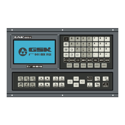
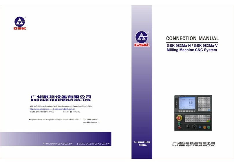
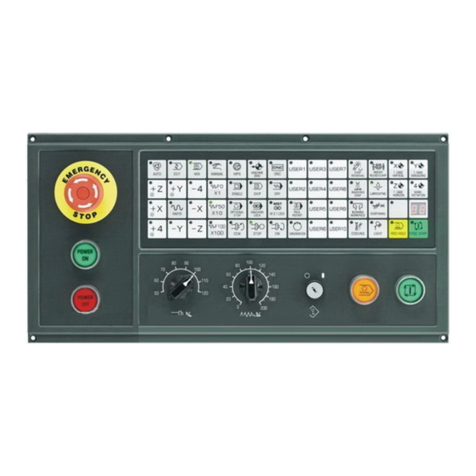
GSK983M-H/M-V Milling CNC System Connection Manual
I
CONTENTS
Precautions for Connection ............................................................. 1
1 Interface Layout of the System ....................................................... 3
2 Interface Layout of CPU Board ........................................................ 4
3 Interface Layout of Position Control Board ........................................... 5
4 Interface Layout of I/O Board ........................................................ 6
5 Interface Layout of MDI/LCD Panel .................................................... 7
6 Interface of Machine Operator Panel .................................................. 8
7 Connection Layout .................................................................... 9
8 PC Communication cable .............................................................. 10
9 Connection Scheme for External MPG .................................................. 11
10 Signal Cables for Keyboard ......................................................... 12
11 Display Signal Cables .............................................................. 13
12 Communication Cables of Operator Panel ............................................. 14
13 Signal Cables for Connecting DA98D Drive Unit ...................................... 15
14 Z Axis Connecting Holding Cable of DA98D Drive unit ................................ 16
15 Connecting with Spindle Transformer ................................................ 17
16 Spindle Servo Signal Cable Connecting .............................................. 18
17 Installation of spindle orientation in position input signal from mechanical side .. 19
18 Installation of Z axis 2nd reference point in position input signal from mechanical side
...................................................................................... 20
19 Z Axis Hold and Control connecting method with power on ............................ 21
20 External I/O Unit (X1) ............................................................. 22
21 Communication Cables for I/O Unit .................................................. 23
22 I/O Unit (X1) Input/Output Signal Connection Scheme ................................ 24
23 Definition of I/O Unit (X1) Input/Output Interface ................................. 25
Appendix: Installation dimension ...................................................... 28
GSK983M-V Connection Manual Version Upgrade Registration Form ......................... 34
GSK983M-H/M-V Milling CNC System Connection Manual
Precautions for Connection
1、Requirement of the machine cabinet:
The cabinet installation of the system and driver should apply the full-close
dust-proof design. The temperature difference between the inside and outside of the
cabinet should be below 10℃. Heat exchange system is needed if the above condition is
not met. The ambient temperature around the system should be below 45℃. And the liquids
such as lubricant, coolant should be prevented from entering the inside of the system
components.
2、System fixation position:
Since the main cabinet is the control core of the CNC machine, it should be fixed
in priority at a location that has a little temperature rising, little electromagnetic
disturbance. Due to that the large power spindle driver and feed axis driver produce a
huge heating during their running, so the main cabinet and the I/O unit should be fixed
below them with over 100mm clearance as much as possible. Please refer to the appendix
of this manual for their installation drawing dimensions of the system.
3、Power should be supplied to system by isolation transformer.
It is DC24V power supply that
is from power supply box only for CNC control, connecting this DC24V with another device(for
example brake、valve etc. ) is strictly prohibit, otherwise it is very danger!
4、Ground:
1
GSK983M-H/M-V Milling CNC System Connection Manual
! The machine cabinet must install protective grounding, the demand of grounding must
measure up GB5226.1-2002.It is well grounding that is necessarily for system in working order,
it cannot be in series system of each unit of grounding, it must install ground plate of
cabinet(can use a thick copperplate that thickness is 3mm or more),The ground resistance
in protective grounding must be 4Ω or less. The cable used for protective grounding must
be of a sufficient cross section for each unit to connect ground plate, Generally the cable
is short-thick, and the color of cable is yellow-green.
Powersupply
System
Display panel
OperatorPanel
X
axis
drive
unit
Y
axis
drive
unit
Z
axis
drive
unit
Spindle
drive
unit
I/O
Unit
Grounding block
Electric cabinet
PE
5、Wiring:
The signal cables and control cables of weak current should be distributed far away
from the place where heavy current and heavy electromagnetic disturbance exist. They
should be distributed straightly against interference signal that may occur by twisted
cables.
6、Interference inhibition:
Connect shunt RC loop circuit to the AC coil (Fig.1). And the RC loop circuit should
be fixed as near as possible to the inductive load; connect reversely shunt freewheeling
diode to the DC coil (Fig.2); connect shunt surge absorber to the AC motor coil (Fig.3).
AC220V
+24V
0V
(Fig. 2)
M
3~
Surge
absorber
KM
(Fig. 3)
(Fig. 1)
2
GSK983M-H/M-V Milling CNC System Connection Manual
17 Installation of spindle orientation in position input signal from
mechanical side
GSK983M control unit has been increased a spindle orientation in position input signal to confirm the
current position, so that veracity and reliability are heightened, and it is well to protect magazine and tools.
Control unit does not only detect orientation signal from spindle servo drive, it also detects the spindle
orientation limit switch in position signal from mechanical side when tool is being changed. X48.6 of I/O
unit is the spindle orientation limit switch input signal from mechanical side. Machine tool factory can
install this input signal to detect the orientation position if necessary, (generally, the diameter of proximity
switch is 8mm, and the distance of detection is more than 1mm ), there are two ways to detect the position
signal(detect concave or convexity position). It can be modified the PC parameter N3004.7 to change the
logic of the input signal that is detected normal open or close (default of N3004.7 is 0 for detecting normal
open and concave position). If it need to detect normal close and concave position than it can be modified
the PC parameter N3004.7=1(it means contrary).
Spindle
Proximity
switch
Detect
convexity
Spindle
Detect
concave
M8
Spindle orientation in position
input signal installation scheme
Spindle orientation in position
input signal connection scheme
I/O unit
+24V X48.6 0V
Proximity
switch
Note: The above I/O pin X48.6 which is “spindle orientation in position input signal from
mechanical side” definition is defined in terms of PLC of V5.01, the I/O points definition depends on
different PLC version! It should be checked the PLC user manual when connecting.
19

This manual suits for next models

1

Other GSK Control System manuals

GSK GSK218MC User manual

GSK

GSK GSK218MC User manual

GSK GSK983Ta-H Instruction manual

GSK

GSK GSK983Ta-H Instruction manual

GSK 988T User manual

GSK

GSK 988T User manual

GSK 980TDi User manual

GSK

GSK 980TDi User manual

GSK GSK988TA User manual

GSK

GSK GSK988TA User manual

GSK GSK928TEa User manual

GSK

GSK GSK928TEa User manual

GSK 983Ma-V Instruction manual

GSK

GSK 983Ma-V Instruction manual

GSK GSK983Ma User manual

GSK

GSK GSK983Ma User manual

GSK GSK928TE User manual

GSK

GSK GSK928TE User manual

GSK 218M Instruction manual

GSK

GSK 218M Instruction manual

GSK GSK980TDc User manual

GSK

GSK GSK980TDc User manual

GSK GSK928TE User manual

GSK

GSK GSK928TE User manual

Popular Control System manuals by other brands

Meissner mts2000/02 manual

Meissner

Meissner mts2000/02 manual

GO Systemelektronik BlueBox T4 manual

GO Systemelektronik

GO Systemelektronik BlueBox T4 manual

HBX SNO-0600 installation manual

HBX

HBX SNO-0600 installation manual

Vaillant VR 66/2 installation instructions

Vaillant

Vaillant VR 66/2 installation instructions

Niles WMVC100 Specifications

Niles

Niles WMVC100 Specifications

ABB C581 operating instructions

ABB

ABB C581 operating instructions

Fancom FB.1 manual

Fancom

Fancom FB.1 manual

OKIN JLDK.42.18.14 user manual

OKIN

OKIN JLDK.42.18.14 user manual

Kenwood RC-95 instruction manual

Kenwood

Kenwood RC-95 instruction manual

Smart temp EASY ZONE TOUCH user manual

Smart temp

Smart temp EASY ZONE TOUCH user manual

HWH SPACEMAKER 325 Series Operator's manual

HWH

HWH SPACEMAKER 325 Series Operator's manual

MojoDesk Hand Control 2020 Operation instructions

MojoDesk

MojoDesk Hand Control 2020 Operation instructions

Skov DOL 34H Technical user guide

Skov

Skov DOL 34H Technical user guide

Emec J DIGITAL CL operating manual

Emec

Emec J DIGITAL CL operating manual

West Mountain Radio TARGETuner operating manual

West Mountain Radio

West Mountain Radio TARGETuner operating manual

Philips LDTS07 user guide

Philips

Philips LDTS07 user guide

Norac UC4.5 installation manual

Norac

Norac UC4.5 installation manual

DAB PUMPS ACTIVE DRIVER M/M 1.1 manual

DAB PUMPS

DAB PUMPS ACTIVE DRIVER M/M 1.1 manual

manuals.online logo
manuals.online logoBrands
  • About & Mission
  • Contact us
  • Privacy Policy
  • Terms and Conditions

Copyright 2025 Manuals.Online. All Rights Reserved.