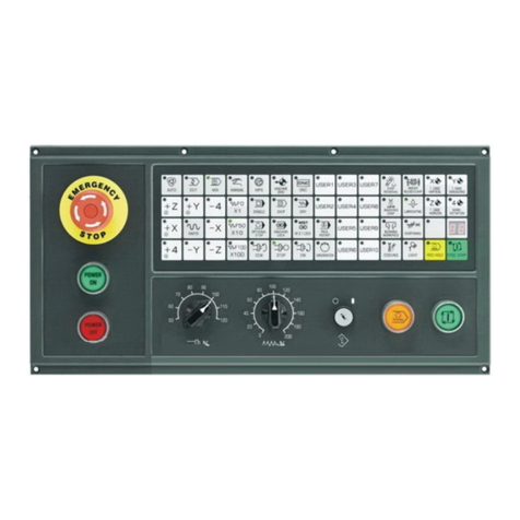
GSK GSK218MC User manual

Official GSK Agents in South Africa
This user manual describes all proceedings concerning the
operations of this CNC system in detail as much as possible. However, it is
impractical to give particular descriptions for all unnecessary or unallowable
system operations due to the manual text limit, product specific applications
and other causes. Therefore, the proceedings not indicated herein should
be considered impractical or unallowable.
This user manual is the property of GSK CNC Equipment Co., Ltd.
All rights are reserved. It is against the law for any organization or individual
to publish or reprint this manual without the express written permission of
GSK and the latter reserves the right to ascertain their legal liability.
This User Manual is suitable for the following CNC systems
manufactured by GSK CNC EQUIPMENT CO., LTD.

Official GSK Agents in South Africa
GSK218MC Series Machining Center CNC System PLC & Installation Connection Manual
II
Series No. Product type Structure LED
dimension Remark
GSK218MC Integral 10.4 LED dimension is 10.4 inch by default
GSK218MC-U1 Integral 8.4 LED dimension is 8.4 inch by default
GSK218MC-H Horizontal 8.4 LED dimension is 8.4 inch by default
GSK218MC-H2 Horizontal 10.4 LED dimension is 10.4 inch by default
GSK218MC
GSK218MC-V Vertical 10.4 LED dimension is 10.4 inch by default
Wherein, GSK218MC, GSK218MC-H and GSK218MC-V have
three communication interfaces such as the RS232, USB and
network of which these interfaces are set on the front of the host.
GSK218MC-U1 owns only two communication interfaces
such as the RS232 and USB; the USB interface set on the front of
the host and the RS232 interface set on the back of the host.

Official GSK Agents in South Africa
Preface & Precaution
III
PREFACE
Your Excellency,
It’s our pleasure for your patronage and purchase of this
GSK218MC Series Machining Center CNC System made by GSK CNC
Equipment Co., Ltd.
This manual is the part of the “PLC and Installation Connection
Manual” of Machining Center CNC System User Manual for
GSK218MC Series, which is introduced its programming method and
installation connection
In order to guarantee the product is operated with a safe, normal
and effective situation, it is necessary to carefully read this manual
before installing and using this product.
Chinese version of all technical documents in Chinese and
English languages is regarded as final.

Official GSK Agents in South Africa
GSK218MC Series Machining Center CNC System PLC & Installation Connection Manual
IV
SECURITY PRECAUTION
Accident may occur by improper operation! This system
only can be operated by authorized and qualified personnel.
Especial prompt: The system power installed on (inside) the
cabinet is the special-purpose one made by GSK CNC system.
Never attempt to use for other purposes by this power. Otherwise,
tremendous hazard may occur!

Official GSK Agents in South Africa
Preface & Precaution
V
警告、注意和注释的说明
STATMENT!
zIn this manual we have tried as much as possible to describe all
various matters. However, we cannot describe all the matters which
must not be done, or which cannot be done, because there are so
many possibilities. Therefore, matters which are not especially
described as possible in this manual should be regarded as
“im
poss
i
b
l
e
”
WARNING!
zThoroughly read this manual and user manual issued by the machine
manufacturer, and strictly operate the machine based upon the
requirement of this manual before installing, programming and
operating the machine; otherwise, possibly causing damage to the
product, machine itself, as well the obsolete workpiece or injury to the
user.

Official GSK Agents in South Africa
GSK218MC Series Machining Center CNC System PLC & Installation Connection Manual
VI
All specifications and designs are subject to change without notice.
NOTICE!
zThe product functions and technical indexes (such as accuracy,
velocity) described in this manual are only directed against this
product. The CNC installed this product, the actual function
configuration and the technical capacity are determined by the
machine manufacturer; the function configurations of the CNC
machine and technical indexes are subjected on the manual issued
by the machine builder.

Official GSK Agents in South Africa
Preface & Precaution
VII
SAFETY PRECAUTIONS
■Transportation and Storage
zDo not pile up the carton over 6 layers.
zDo not climb, stand on the carton; do not place heavy objects on it.
zDo not drag or move the products using the cables connected with the product.
zDo not impact, scratch the panel and screen.
zAvoid from the damp, the sunshine and the rain on the product carton.
■Unpacking inspection
zCheck whether it is your purchased product after unpacking the carton.
zCheck whether the product is damaged during transporting.
zCheck whether the components are prepared or damaged comparing with the
packing list.
zIt is necessary to contact our company immediately if the product type is
inconsistent with the packing list, lack of accessories or damage in
transportation.
■Wiring
zThe person who executes the wiring and inspection should have the
corresponding professional capacity.
zThe product should be reliably grounded, and its resistance should be less than
0.1Ωand can not be used the neutral conductor (zero cable) to replace the
ground wire.
zThe wiring should be correct and firm, otherwise, possibly causing the
malfunction in product or unexpected result.
zThe surge absorb diode connected with the product should be linked based upon
the described direction, otherwise, it may damage the product.
zBefore Inserting/pulling out the plug or opening the main cabinet of the product, it

Official GSK Agents in South Africa
GSK218MC Series Machining Center CNC System PLC & Installation Connection Manual
VIII
is important to cut off the product’s power.
■Inspection and maintenance
zCut off the power before inspecting and maintaining or changing the
components.
zCheck the malfunction when the short-circuit or overloading occurs. The
computer can be started after the malfunction is eliminated.
zDo not power ON/OFF frequently for the product, if you want to turn on the
power again after power off, its interval time is 1min. at least.

Official GSK Agents in South Africa
Preface & Precaution
IX
Volume ⅠProgramming Description
Introduce the PLC’s specification, address, basis code and
function code of the GSK218MC series
Volume ⅡOperation Description
Introduce the PLC’s relative operation proceedings of
GSK218MC series
Volume ⅣInstallation and Connection
Introduce the installation, connection and setting method of
the GSK218MC series CNC system
Appendix
Introduce the ladder diagram user guide about the GSK218MC
CNC system matching with the tool magazine
Volume III Function Description
Introduce the PLC’s main function of GSK218MC series

Official GSK Agents in South Africa
GSK218MC Series Machining Center CNC System PLC & Installation Connection Manual
X
SECURITY RESPONSIBILITY
Security responsibility of the manufacturer
——Manufacturer should take responsibility for the design and structure danger of the
motor and the accessories which have been eliminated and/or controlled.
——Manufacturer should take responsibility for the security of the motor and
accessories.
——Manufacturer should take responsibility for the offered information and
suggestions for the user.
Security responsibility of the users
——User should know and understand about the contents of security operations by
learning and training the security operations of the CNC system.
——User should take responsibility for the danger because of increasing, changing or
modifying the original CNC system or accessories by themselves.
——User should take responsibility for the danger without following the operations,
maintenances, installations and storages described in the manual.
This manual is stored by the last user.
Sincerely thanks for your friendly supporting of GSK’s
products!

Official GSK Agents in South Africa
Content
XI
CONTENTS
VOLUME I PROGRAMMING ............................................................................................1
CHAPTER ONE SQUENCY PROGRAMMING COMPILATION SCHEDULE......2
1.1 GSK218MC Series PLC Specification ................................ 2
1.2 Concept of the Sequence Programming .............................. 2
1.3 Distribution Interface (Step one) ..................................... 3
1.4 Ladder Diagram Compilation (Step two) .............................. 3
1.5 Sequence Programming Debugging (Step 3) .......................... 3
CHAPTER TWO SEQUENCE PROGRAMMING........................................................5
2.1 Performance Process of Sequence Programming ...................... 5
2.2 Cycle Performance ................................................ 6
2.3 Priority Sequence of the Execution (the 1st Level, the 2nd level) ............ 6
2.4 Sequence Program Structure ......................................... 7
2.5 Input/output Signal Treatment......................................... 9
2.5.1 Input Signal Treatment.............................................................................. 9
2.5.2 Treatment of the Output Signal ........................................................... 10
2.5.3 Distinguish of Signal State Between 1st Level and 2nd Program....... 10
2.6 Interlocking ...................................................... 11
CHAPTER THREE PLC ADDRESS .............................................................................13
3.1 Machine →PLC address (X) ...................................... 13
3.1.1 X Address on I/O Input............................................................................ 14
3.1.2 X Address on MDI Panel......................................................................... 14
3.2 PLC →Address of Machine Tool Side (Y) ........................... 16
3.2.1 Y Address on I/O Output Port ................................................................. 16
3.3 PLC →CNC Address (G) .......................................... 18
3.4 CNC →PLC Address (F) .......................................... 19
3.5 Internal Replay Address (R) ........................................ 19
3.6 Nonvolatile Relay Address (K) ...................................... 20
3.7 Information Display Request Address (A) ............................ 20
3.8 Counter Address (C) .............................................. 21
3.9 Counter Preset Value Address (DC) ................................. 21
3.10 Timer Address (T) ............................................... 21
3.11 Presetting Value Address of Timer (DT) ............................. 21
3.12 Data Table Address (D)........................................... 21
3.13 Address Mark (L) ................................................ 21
3.14 Subprogram Number (P) ......................................... 22
CHAPTER FOUR PLC BASIS CODE...........................................................................23
4.1 RD, RD.NOT, WRT, and WRT.NOT Codes ........................... 23
4.2 AND, AND.NOT Codes ............................................ 24
4.3 OR, OR.NOT Codes .............................................. 25

Official GSK Agents in South Africa
GSK218MC Series Machining Center CNC System PLC & Installation Connection Manual
XII
4.4 OR. STK Code .................................................. 25
4.5 AND. STK Code ................................................. 26
CHAPTER FIVE PLC FUNCTION CODE................................................................... 27
5.1 END1 (The 1st Level Sequence Program End) ....................... 28
5.2 END2 (The 2nd Sequence Program End) ............................ 28
5.3 CALL (Call Subprogram) .......................................... 28
5.4 CALLU (Unconditionally Call Subprogram) .......................... 29
5.5 SP (Subprogram) ................................................ 30
5.6 SPE (End of Subprogram)......................................... 30
5.7 SET (Replacement/Setting) ....................................... 31
5.8 RST (Resetting) ................................................. 31
5.9 JMPB (Mark Number Skip) ........................................ 32
5.10 LBL (Mark Number) ............................................. 33
5.11 TMR (Timer).................................................... 33
5.12 TMRB (Fixed Timer)............................................. 34
5.13 TMRC (TIMER) ................................................. 35
5.14 CTR (Binary Counter) ........................................... 36
5.15 DEC (Binary Decoding) .......................................... 38
5.16 COD (Binary System Code Conversion) ........................... 39
5.17 COM (Concentric Line Control) ................................... 40
5.18 COME (Concentric Line Control End) .............................. 41
5.19 ROT (Binary Rotation Control) .................................... 41
5.20 SFT (Register Displacement/Shifting).............................. 44
5.21 DIFU (Rising Edge Detection) .................................... 45
5.22 DIFD (Descending Edge Detection) ............................... 46
5.23 COMP (Comparison of Binary Number) ............................ 47
5.24 COIN (Consistency Comparison).................................. 48
5.25 MOVN (Data Transmission) ...................................... 48
5.26 MOVB (Transmission of 1 Byte)................................... 49
5.27 MOVW (Transmission of Two Bytes)............................... 50
5.28 XMOV (Binary Indexed Data Transmission) ........................ 51
5.29 DSCH (Binary Data Index) ....................................... 52
5.30 ADD (Binary Addition) ........................................... 53
5.31 SUB (Binary Subtraction) ........................................ 54
5.32 ANDF (Bit-by-bit AND) ........................................... 55
5.33 ORF (Bit-by-bit OR) ............................................. 56
5.34 NOT (Bit-by-bit NOT) ............................................ 57
5.35 EOR (Exclusive OR) ............................................ 58
CHAPTER SIX COMPILATION LIMIT OF LADDER DIAGRAM......................... 60
VOLUME II OPERATION EXPLANATION ................................................................... 62
CHAPTER ONE PLC INTERFACE DISPLAY ........................................................... 64
1.1 GSK218MC Series Automatic Operation in PLC ON................. 64
1.2 Program-Controlled Interface Display ............................... 64

Official GSK Agents in South Africa
Content
XIII
1.2.1 INFO Interface ........................................................................................ 64
1.2.2 PLCGRA Interface .................................................................................. 66
1.2.3 PLCPAR Interface................................................................................... 66
1.2.4 PLCDGN Interface.................................................................................. 67
1.2.5 PLCTRAE Interface ................................................................................ 68
CHAPTER TWO PLC PROGRAMMING OPERATION...........................................72
2.1 Brief ............................................................ 72
2.2 Basis Code ...................................................... 73
2.3 Operation Explanation of Ladder Diagram ........................... 74
2.4 Function Code ................................................... 77
2.5 Command Table .................................................. 78
2.6 Compilation Command ............................................ 79
2.7 PLC Operation Steps.............................................. 80
CHAPTER THREE PLC ADDRESS AND PARAMETER SETTING.......................82
3.1 Nonvolatile/Hold Relay ............................................ 82
3.2 Timer ........................................................... 84
3.3 Data List......................................................... 85
3.4 Counter ......................................................... 86
3.5 M function corresponding to F address .............................. 87
CHAPTER FOUR USER EXPLANATION OF LADDER DIAGRAM SOFTWARE
EDIT.....................................................................................................................................90
4.1 Brief ............................................................ 90
4.2 Software Introduction.............................................. 90
4.2.1 Software Start ......................................................................................... 90
4.2.2 Function Introduction .............................................................................. 91
4.3 Software Operation ............................................... 92
4.3.1 Toolbar ………………………………………………………………………92
4.3.2 Selection of Figure.................................................................................. 94
4.3.3 Editing of Figure...................................................................................... 95
4.3.4 Ladder Diagram Note.............................................................................. 96
4.3.5 Leading-out............................................................................................. 98
VOLUME III FUNCTION EXPLANATION ...................................................................100
CHAPTER ONE CONTROLLABLE AXIS................................................................102
1.1 Output of Axis Movement ......................................... 102
1.2 Servo Signal Ready.............................................. 103
CHAPTER TWO OPERATION PREPARATION.....................................................104
2.1 ESP ........................................................... 104
2.2 CNC Overtravel Signal ........................................... 104
2.3 Alarm Signal .................................................... 105
2.4 Selection of Operation Method .................................... 106
2.5 State Signal Output .............................................. 106

Official GSK Agents in South Africa
GSK218MC Series Machining Center CNC System PLC & Installation Connection Manual
XIV
CHAPTER THREE MANUAL OPERATION............................................................ 108
3.1 JOG Feed/Incremental Feed ..................................... 108
CHAPTER FOUR REFERENCE POSITION RETURN........................................... 112
4.1 Manual Reference Position Return ................................ 112
4.2 Return to Reference Position Detection Signal ...................... 113
4.3 Area Detection Signal ........................................... 114
CHAPTER FIVE AUTOMATICAL OPERATION................................................... 116
5.1 Cycle Start/ Feed Dwell .......................................... 116
5.2 Resetting ...................................................... 118
5.3 Program Testing ................................................ 119
5.3.1 Machine Tool Lock .................................................................................119
5.3.2 Dry Run …………………………………………………………………….119
5.3.3 Single Block .......................................................................................... 120
5.4 Skip Optional Block ............................................. 121
5.5 Program Restart ................................................ 122
CHAPTER SIX FEEDRATE CONTROL................................................................... 124
6.1 Rapid Traverse Rate ............................................ 124
6.2 Feedrate Override............................................... 124
6.3 Override Cancellation............................................ 125
CHAPTER SEVEN MISCELLANEOUS FUNCTION.............................................. 126
7.1 M Code Miscellaneous Function .................................. 126
7.2 S Code Miscellaneous Function................................... 127
7.3 T Code Miscellaneous Function ................................... 128
7.4 Miscellaneous Function Lock ..................................... 132
CHAPTER EIGHT SPINDLE VELOCITY FUNCTION.......................................... 134
8.1 Spindle Velocity Control Method................................... 134
8.1.1 Gear Spindle ......................................................................................... 134
8.1.2 Analog Spindle ...................................................................................... 134
8.2 Rigid Tapping................................................... 136
CHAPTER NINE PROGRAMMING CODE.............................................................. 138
9.1 User Macro Program ............................................ 138
9.2 Canned Cycle .................................................. 140
CHAPTER TEN DISPLAY/SETTING........................................................................ 142
10.1 Clock Function ................................................ 142
10.2 Operation Record Display ....................................... 142
10.3 Help Function ................................................. 142
CHAPTER ELEVEN MEASURING ........................................................................... 144
11.1 Skip Function.................................................. 144
CHAPTER TWELVE PANEL LOCK SETTING ...................................................... 146
VOLUME IV INSTALLATION & CONNECTION...................................................... 157

Official GSK Agents in South Africa
Content
XV
CHAPTER ONE SYSTEM CONFIGURATION &INSTALLATION ....................159
1.1 System Composition ............................................. 159
1.2 System Installation and Connection ................................ 159
1.3 CNC System Appearance Installation Dimension Figure .............. 161
1.4 Additional Panel Figure........................................... 167
CHAPTER TWO CONNECTION BETWEEN EQUIPMENTS...............................169
2.1 Connection Diagram of External System ............................ 169
2.1.1 Layout of Interface Position ...................................................................169
2.1.2 Pulse Servo Connection Schematic.......................................................171
2.1.3 Bus Servo Connection Schematic .........................................................172
2.1.4 Five-Linkage Servo Connection Schematic Using Bus Technology .......173
2.2 Connection Between System and Drive Unit......................... 174
2.2.1 System Interface Figure.........................................................................174
2.2.2 Interface Signal List ...............................................................................174
2.2.3 Signal Explanation .................................................................................175
2.2.4 Cable Connection Figure .......................................................................177
2.2.5 GSK-LINK Cable Connection Figure .....................................................179
2.2.6 External Wiring Figure of GL100 Bus Extension Module .......................181
2.3 RS232 Standard Series Interfaces ................................. 182
2.4 Connection of MPG/Hand Unit..................................... 183
2.4.1 Interface Signal Figure...........................................................................183
2.4.2 Explanation of Interface Signal ..............................................................183
2.5 Connection of Spindle Unit ........................................ 186
2.5.1 Interface Signal Table ............................................................................186
2.5.2 Explanation of Interface Signal ..............................................................186
2.5.3 Cable Connection Figure .......................................................................187
2.6 System Power Interface .......................................... 189
2.7 External Power Control Interface .................................. 189
2.8 Connection of Communication Cable ............................... 189
CHAPTER THREE I/O INTERFACE OF MACHINE CONTROL.........................191
3.1 Interface Signal Table ............................................ 191
3.2 Interface Input................................................... 191
3.2.1 Interface Circuit Input.............................................................................191
3.2.2 Interface Circuit of Hand Unit.................................................................192
3.2.3 Interface Definition of Signal Input .........................................................193
3.3 Interface Output ................................................. 196
3.3.1 Interface Circuit Output ..........................................................................196
3.3.2 Interface Definition of Signal Output ......................................................197
CHAPTER FOUR MACHINE DEBUGGING............................................................199
4.1 Debugging Preparation ........................................... 199
4.2 System Power-ON ............................................... 200
4.3 ESP and Limit ................................................... 200
4.4 Gear Ratio Adjustment ........................................... 202

Official GSK Agents in South Africa
GSK218MC Series Machining Center CNC System PLC & Installation Connection Manual
XVI
4.5 Backlash Compensation ......................................... 204
4.6 Setting Related with Drive unit .................................... 205
4.7 Machine Tool Pitch Compensation................................. 206
4.8 Mechanical Zero Return (Machine Zero Return) ..................... 213
4.8.1 Mechanical Zero Return in Pulse Method ............................................. 214
4.8.2 Servo Zero Return Function Setting of Bus Type .................................. 217
4.9 Input/Output Signal Control of Spindle Positive/Negative ............. 223
4.10 Spindle Automatic Gear-shift Control ............................. 225
4.11 External Cycle Start & Feed Hold................................. 227
4.12 External Editing Lock and the External Operation Panel Lock ........ 228
4.13 Cooling, Lubrication and Chip-Removal Control .................... 228
4.14 Setting Related to Feedrate ..................................... 229
4.15 Setting Related with Tapping Parameter .......................... 231
4.16 Setting for the 4th Axis .......................................... 234
4.17 Setting About the Bus Servo..................................... 236
APPENDIX .......................................................................................................................... 243
APPENDIX I LADDER DIAGRAM USAGE GUIDE OF GSK218MC SERIES WITH
CONE TYPE TOOL-MAGAZINE..................................................................................... 245
I. Cautions When Using the Cone Type Tool-Magazine Ladder Diagram .. 245
II. Configuration and Definition of PLC I/O Address and Internal Software
Components …………………………………………………………………….245
III. The Usage and Maintenance of the Cone Tool Magazine.................... 270
IV. The Macro Note Matching with the Cone Tool Magazine..................... 278
APPENDIX II LADDAR DIAGRAM USE GUIDE OF GSK218MC SERIES
MATCHING WITH DISC TOOL MAGAZINE................................................................. 281
I. The application precautions of the disc tool magazine......................... 281
II. The Configuration and Definition of the PLC I/O Address and Internal Soft
Component ……………………………………………………………………281
III. The Usage and Maintenance with Manipulator Tool Magazine.............. 310
IV. Macro Note with Disk Tool Magazine ....................................................... 317
APPENDIX III FILE FORMAT OF LADDER DIAGRAM CONFIGURATION........ 319
I. F Signal and Meaning of the M Code M00---M99....................................... 319
II. That the “%” Takes One Single Line Means that the M code Information
Storage is End …………………………………………………………………….319
III. The Code and Meaning of the X Signal X0.0---X6.7 ................................ 319
IV. The Code and Meaning of the Y Signal Y0.0---Y5.7 ................................ 320
V. The Code and Meaning of the K Signal K6.0---K63.7............................... 320
VI. The Code and Meaning of the A Signal A0.0---A31.7 ........................... 320
VII. end//End Mark.....……………………………………………………………….320

Official GSK Agents in South Africa
1
Volume I Programming
VOLUME I PROGRAMMING

Official GSK Agents in South Africa
GSK218MC Series Machining Center CNC System PLC & Installation Connection Manual
2
Volume I Programming
CHAPTER ONE SQUENCY PROGRAMMING COMPILATION
SCHEDULE
1.1 GSK218MC Series PLC Specification
GSK218MC series PLC specification is shown below:
Table 1-1-1
1.2 Concept of the Sequence Programming
The so-called sequence programming is the one that performing the logic control to the
machine tool and its relative equipments.
After the programming is converted into some kind of format, CPU can be performed its code
and calculation treatment for it, and its fruits can be memorized to RAM. CPU can be rapidly read
each code stored in the memory, which can be performed the programming according to the
calculation operation.
Specification GSK218MC Series PLC
Programming language Ladder
Program level 2
The 1st level program execution cycle 8ms
Basis code average treatment time 5μs
Programming capacity 4700 steps
Code Basis code + function code
Internalrelay (R)
PLC alarm detection (A)
Nonvolatile memory area
Timer (T)
Counter (C)
Database (D)
Nonvolatilerelay (K)
Counter prevalue data register (DC)
Timer prevalue data register (DT)
Subprogram (P)
Mark (L)
Input signal of NC side (F)
Signal outputs to the NC side (G)
0~511 (byte)
0~31(byte)
0~127 (word)
0~127 (word)
0~255 (word)
0~63 (byte)
0~127(word)
0~127(word)
0~99
0~99
0~63(byte)
0~63(byte)
I/O module (X)
(Y)
0~63 (byte)
0~47 (byte)

Official GSK Agents in South Africa
Chapter One Squency Programming Compilation Schedule
3
Volume I Programming
The compilation of the sequence programming starts with the ladder diagram.
1.3 Distribution Interface (Step one)
The interface can be distributed after confirming the control object and calculating the points of
the corresponding input/output signal.
Refer to the Chapter Four Input/output interface signal table in the Volume Four Installation and
Connection when distributing the interface.
1.4 Ladder Diagram Compilation (Step two)
The required control operation can be expressed by the ladder diagram with the on-line
compilation of the Gsk218MC series ladder diagram. The functions, such as the timer and counter,
can not be expressed by relay symbols, which can be indicated by the specified function code
symbols.
The compiled ladder diagram should be stored and converted into the corresponding PLC
codes before operating, namely, the so-called instruction list.
1.5 Sequence Programming Debugging (Step 3)
The sequence programming can be debugged using the following methods:
Debugging with emulator
The machine tool can be replaced by an emulator (it composes of the lights and switches).
ON/OFF of the switch means the signal input state of the machine tool, and the ON/OFF of
the light is the signal state output.
Debugging with actual operation
Debug on the actual machine tool. It is better to prepare the precautions before debugging,
otherwise an unexpected behavior may occur.

Official GSK Agents in South Africa
GSK218MC Series Machining Center CNC System PLC & Installation Connection Manual
4
Volume I Programming
This manual suits for next models
4
Table of contents
Other GSK Control System manuals
Popular Control System manuals by other brands

Sutter Instrument
Sutter Instrument SmartShutter Lambda SC Operation manual

GE
GE Mark VIe System guide

benjo
benjo IRD 120A operating instructions

Trane
Trane BAYCC24VK01A Installer's guide

Ducasa
Ducasa Smart Command Tevolve Installation and operating manual

D.Electron
D.Electron CNC Z32 Florenz Series Programming guide