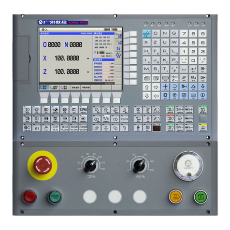
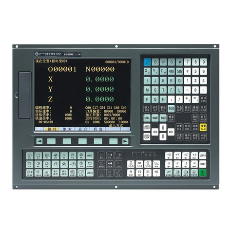
GSK GSK983Ma User manual

This user manual describes all proceedings concerning the
operations of this CNC system in detail as much as possible. However, it is
impractical to give particular descriptions for all unnecessary or unallowable
system operations due to the manual text limit, product specific applications
and other causes. Therefore, the proceedings not indicated herein should
be considered impractical or unallowable.
This user manual is the property of GSK CNC Equipment Co., Ltd. All
rights are reserved. It is against the law for any organization or individual
to publish or reprint this manual without the express written permission of
GSK and the latter reserves the right to ascertain their legal liability.

GSK983Ma Milling Machine Center CNC System User Manual
II
Preface
Your Excellency,
It’s our pleasure for your patronage and purchase of this
GSK983Ma Milling machining center CNC system made by GSK CNC
Equipment Co., Ltd.
GSK983Ma User Manual divides into three parts, that is,
“Programming”, “Operation” and “Appendix”.
Special prompt: 24V switch power box matched with the system is the
special power offered by our company.
User can not use the power to other purpose. Otherwise, the
enormous danger may occur!

Safty Caution
III
Safty Caution
!Accident may occur by improper connection and operation!This system
can only be operated by authorized and qualified personnel. Please
carefully read this manual before using!
Refer to user manual issued by the manufacturer carefully
before installing, programming and operating this product, and
the relative operation should be performed based upon the user
manual strictly.

GSK983Ma Milling Machine Center CNC System User Manual
IV
Statement
●In this manual we have tried as much as possible to describe all the
various matters. However, we cannot describe all the matters which
must not be done, or which cannot be done, because there are so
many possibilities. Therefore, matters which are not especially
described as possible in this manual should be regarded as
“impossible”
Notice
●The product function and qualification (such as the accuracy, speed)
described in this manual is only for this product, which is installed the
CNC machine of this product. The actual function configuration and
technical capacity are determined by the setting of the manufacturer.
●The system is matched with the standard operation panel, but its
function of each key is defined by the PLC program (ladder diagram). It
is very important to note that the function of the key in this manual is
described for the standard PLC program!
●Refer to the manual issued by the manufacturer for the function of
each key on the operation panel and the meaning.

Cautions
V
Cautions
■Transportation and storage
●Do not pile the carton more than six layers.
●Do not climb, stand or place the heavy on the carton.
●Do not drag or move the production using the cable connected with the
production.
●Do not bump the carton or scratch the panel and the display screen.
●The product packing should be avoid the damp, sun and rain.
■Checking
●Confirm whether it is your purchased product after opening the packing.
●Confirm whether the product is being damaged during transporting.
●Confirm whether the spare parts are completed or being damaged.
●If the unconfirmed type, the lack of accessories or the damage of transportation
may occur, touch our company freely.
■Wiring
●The wiring or checking should be performed with the professional.
●Refer to the Connection Manual for the wiring.
●The product should be grounded, and the grounding resistance should be less
than 0.1Ω. The neutral line (zero line) can not be replaced by the grounding.
●The wiring should be correct and firm, so that the product malfunction or
undesired result may occur.
●The surge absorber diode connected with this product should be connected in
the specified direction, or the product may be damaged.
●The power should be cut off when Inserting or pulling out the plug or opening the
machine of the product
■Detection
●The man who is the professional can be detected the machine.
●The power should be cut off before detecting or repairing or changing the
elements.
●Checking the malfunction when the short-circuit or the overloading occurs, it can
be started after the malfunction is eliminated.
●Never attempt to turn on/off the product frequently, if you want to start it again
after the power is turned off, it is necessary to wait for 1min at least.

GSK983Ma Milling Machine Center CNC System User Manual
VI
Security Responsibility
Security responsibility for manufacturer
——Manufacturer should be take responsibility for the danger of the motor and the
accessories which have been eliminated and/ or controlled in design and in
structure.
——Manufacturer should be take responsibility for the security of the motor and
accessories.
——Manufacturer should be take responsibility for use information and suggestion
offered to the user.
Security responsibility for the user
——User should be know and understand about the content for security operation by
learning and training the security operation of the motor.
——User should be take responsibility for the security and danger about the increase,
change or original motor modification or accessory by themselves.
——User should be take responsibility for operating, adjusting, maintaining, installing
and storing the products without following the descriptions of this manual,
All specifications and design are subject to change without further
notice.
This manual is reserved by final user.
Sincere thanks for your friendly patronage for the products
made by GSK CNC Equipment Co., Ltd.
Chinese version of all technical documents in Chinese and
English languages is regarded as final.

List
VII
List
Programming
Programming.......................................................................................................................................1
Chapter One General........................................................................................................................1
1.1 GENERAL............................................................................................................................................... 1
1.2 CAUTIONS FOR READING THIS MANUAL .................................................................................................. 1
Chapter Two Specification ................................................................................................................3
Chapter Three Programming ..........................................................................................................13
3.1 WHAT IS PROGRAMMING ........................................................................................................................ 13
3.2 PROGRAM STRUCTURE ........................................................................................................................... 13
3.2.1 Block............................................................................................................................................. 14
3.2.2 Program Word............................................................................................................................. 14
3.2.3 Input format.................................................................................................................................. 16
3.2.4 Decimal point programming...................................................................................................... 17
3.2.5 The maximum command value................................................................................................. 18
3.2.6 Program number......................................................................................................................... 19
3.2.7 Sequence number ...................................................................................................................... 20
3.2.8 Skip to optional block................................................................................................................. 20
3.3 DIMENSION WORD.................................................................................................................................. 21
3.3.1 Controlled axis............................................................................................................................. 21
3.3.2 Setting unit................................................................................................................................... 22
3.3.2.1 The least input increment and the least movement unit .......................................................... 22
3.3.2.2 10 folds input unit.................................................................................................................... 23
3.3.3 The maximum stroke.................................................................................................................. 24
3.3.4 Program origin and coordinate system.................................................................................... 24
3.3.5 The coordinate system and the machining start point........................................................... 24
3.3.6 Workpiece coordinate system................................................................................................... 25
3.3.7 Reference (position) point ......................................................................................................... 26
3.3.8 Absolute and incremental commands ..................................................................................... 26
3.4 FEED FUNCTION (F FUNCTION)............................................................................................................... 27
3.4.1 Rapid traverse rate..................................................................................................................... 27
3.4.2 Cutting Feedrate......................................................................................................................... 28
3.4.3 Feedrate decelerates to 1/10.................................................................................................. 29
3.4.4 Synchronous feed (feed/rev.).................................................................................................... 29
3.4.5 F1-digit Feed ............................................................................................................................... 30
3.4.6 Automatic acceleration/deceleration........................................................................................ 30
3.4.7 Automatic Corner Modification.................................................................................................. 31
3.4.7.1 The automatic modification of inner corner............................................................................ 31
3.4.7.2 The change of inner side arc cutting........................................................................................ 34
3.5 PREPARATION FUNCTION (G FUNCTION)................................................................................................. 35
3.5.1 Plain Selection (G17, G18, G19).............................................................................................. 38
3.5.2 Positioning (G00)........................................................................................................................ 38
3.5.3 Single Direction Positioning (G60)........................................................................................... 39
3.5.4 Linear interpolation (G01)........................................................................................................ 40
3.5.5 Circular Interpolation (G02, G03)............................................................................................. 42
3.5.5.1 Circular interpolation without an additional axis .................................................................... 42
3.5.5.2 Arc interpolation with additional axis..................................................................................... 44
3.5.6 Sine curve interpolation............................................................................................................. 45
3.5.7 Thread Cutting (G33) .............................................................................................................. 46
3.5.8 Automatic reference position return (Reference position G27
~
G30)................................ 48
3.5.8.1 Reference position return check (G27).................................................................................... 48
3.5.8.2 Automatically return to the reference position (G28).............................................................. 48
3.5.8.3 Return from the reference position automatically (G29)......................................................... 49
3.5.8.4 2nd, 3rd and 4th reference position return (G30)................................................................. 51
3.5.9 Dwell (G04).................................................................................................................................. 51

GSK983Ma Milling Machine Center CNC System User Manual
VIII
3.5.10 Exact stop check (G09)............................................................................................................52
3.5.11 Exact stop check (G60) and cutting mode (G64).................................................................52
3.5.12 Coordinate system setting (G92)............................................................................................52
3.5.13 Workpiece coordinate system (G54
~
G59)..........................................................................53
3.5.14 Workpiece coordinate system changes by the program command ..................................56
3.5.15 Automatic coordinate system setting.....................................................................................56
3.5.16 Inch/Metric conversion (G20, G21)........................................................................................57
3.5.17 Stored stroke limit (G22, G23)................................................................................................57
3.5.18 Skip Function (G31)..................................................................................................................60
3.6 COMPENSATION FUNCTION.....................................................................................................................61
3.6.1 Tool length compensation (G43, G44, G49) ...........................................................................61
3.6.2 Tool position offset (G45
~
G48)................................................................................................64
3.6.3 Cutter compensation (G40
~
G42)............................................................................................71
3.6.3.1 The function of cutter compensation .......................................................................................71
3.6.3.2 Offset value (D code)...............................................................................................................71
3.6.3.3 Offset vector ............................................................................................................................71
3.6.3.4 Plane selection and vector........................................................................................................72
3.6.3.5 G40,G41 and G42...............................................................................................................72
3.6.3.6 Details of cutter compensation C.............................................................................................74
3.6.4 Functions D and H ....................................................................................................................102
3.6.5 External tool offset ....................................................................................................................102
3.6.6 Enter offset value from the program (G10) .........................................................................103
3.6.7 Scaling (G50, G51)...................................................................................................................103
3.6.8 Coordinate system rotation (G68, G69).................................................................................105
3.6.8.1 Format....................................................................................................................................106
3.6.8.2 Relationships with other functions ........................................................................................108
3.6.8.3 Parameter............................................................................................................................... 111
3.6.8.4 In the case of the command repetition...................................................................................112
3.7 THE FUNCTION OF CYCLE MACHINING ..................................................................................................113
3.7.1 The function of the external operation ................................................................................... 113
3.7.2 Canned cycle (G73, G74, G76, G80
~
G89)......................................................................... 113
3.7.2.1 the repetition of the canned cycle ..........................................................................................130
3.7.3 The initial point and point R in the canned cycle (G98, G99).............................................135
3.7.4 Rigid tapping cycle (G180, G184) ..........................................................................................136
3.7.4.1 Brief.......................................................................................................................................136
3.7.4.2 Command format...................................................................................................................136
3.7.4.3 Explanation............................................................................................................................138
3.7.4.4 Limitation ..............................................................................................................................138
3.7.4.5 Examples................................................................................................................................138
3.8 SPINDLE FUNCTION (S FUNCTION), TOOL FUNCTION (T FUNCTION), MISCELLANEOUS FUNCTION (M
FUNCTION), THE 2ND MISCELLANEOUS FUNCTION (B FUNCTION) ................................................................139
3.8.1 Spindle function (S function)....................................................................................................140
3.8.1.1 S2 digit...................................................................................................................................140
3.8.1.2 S4 digit.................................................................................................................................140
3.8.2 Constant surface speed control..............................................................................................140
3.8.2.1 Command method..................................................................................................................140
3.8.2.2 Spindle speed rate..................................................................................................................141
3.8.2.3 The clamping of the Max. Spindle speed...............................................................................141
3.8.2.4 Rapid feedrate (G00) .............................................................................................................141
3.8.3 Tool function (T function)..........................................................................................................142
3.8.4 Miscellaneous function (M function).......................................................................................142
3.8.5 The 2nd Miscellaneous Function (B function).......................................................................143
3.9 SUB-PROGRAM......................................................................................................................................143
3.9.1 The Manufacture of the Sub-program....................................................................................143
3.9.2 The Performance of the Sub-program...................................................................................144
3.9.3 Special usage ............................................................................................................................144
3.10 USER MACRO PROGRAM.....................................................................................................................146
3.10.1 General Brief............................................................................................................................146

List
IX
3.10.2 Variable.................................................................................................................................... 146
3.10.2.1 The Description of the Variable........................................................................................... 147
3.10.2.2 The Notation of the Variable ............................................................................................... 147
3.10.2.3 Undefined Variable.............................................................................................................. 147
3.10.2.4 The Display and Setting of the Variable Value.................................................................... 148
3.10.3 Type of the Variable................................................................................................................ 148
3.10.3.1 Local Variable # 1~# 33..................................................................................................... 149
3.10.3.2 Common variable #100~#149, #500~#511.................................................................. 149
3.10.3.3 System Variable (It is used for the user Macro program B) ................................................ 149
3.10.4 Operation command............................................................................................................... 158
3.10.4.1 the Define and Replacement of the Variable ....................................................................... 159
3.10.4.2 The Add Operation.............................................................................................................. 159
3.10.4.3 Multiply Operation (The selection of the Macro B)............................................................ 159
3.10.4.4 Function (Macro program B)............................................................................................... 159
3.10.4.5 Compound Operation.......................................................................................................... 160
3.10.4.6 Operation sequence change by the [ ]............................................................................. 160
3.10.4.7 Accuracy.............................................................................................................................. 160
3.10.4.8 Some Cautions for reducing the accuracy........................................................................... 161
3.10.5 Control command................................................................................................................... 161
3.10.5.1 Branch (GOTO)................................................................................................................... 161
3.10.5.2 Repeat the WHILE (Macro program B).............................................................................. 162
3.10.6 The Compilation of the User Macro Program Body and Memory................................... 165
3.10.6.1 The Compilation of the User Macro Program Body ........................................................... 165
3.10.6.2 The Memory of the User Macro Program Body.................................................................. 166
3.10.6.3 Macro Program Statement and NC Statement..................................................................... 166
3.10.7 Macro Call command............................................................................................................. 168
3.10.7.1 Simple Call.......................................................................................................................... 168
3.10.7.2 Modal call............................................................................................................................ 173
3.10.7.3 Multiple Call ....................................................................................................................... 174
3.10.7.4 Multiple Modal Call............................................................................................................ 174
3.10.7.5 Macro Program Call by G code........................................................................................... 175
3.10.7.6 Call the Sub-program by M Code ..................................................................................... 176
3.10.7.7 Call the Macro Program by M Code ................................................................................. 177
3.10.7.8 Sub-program Call by the T code.......................................................................................... 177
3.10.7.9 Decimal Position of the Argument ......................................................................................177
3.10.7.10 M98 (Sub-program Call) and G65 (Calling the different between the Macro program bodies)
.............................................................................................................................................................. 178
3.10.7.11 The Nesting and Local Variables of User Macro............................................................... 178
3.10.8 The Relationships with Other Functions............................................................................. 179
3.10.9 Special Codes and Words Used in User Programs.......................................................... 180
3.10.10 Restrictions............................................................................................................................ 181
3.10.11 The Description of the P/S Alarm....................................................................................... 181
3.10.12 Examples of User Macro..................................................................................................... 182
3.10.12.1 Groove Machining............................................................................................................. 182
3.10.13 External Output Command ................................................................................................. 183
3.10.13.1 Open command: POPEN................................................................................................... 183
3.10.13.2 Data Output instruction BPRNT DPRNT ......................................................................... 183
3.10.13.3 Close Instruction PCLOS.................................................................................................. 185
3.10.13.4 Necessary Setting for Using the Function......................................................................... 185
3.10.13.5 Cautions............................................................................................................................. 185
3.10.14 Macro interruption function (Macro B)............................................................................... 185
3.11 TOOL LIFE MANAGEMENT.................................................................................................................. 186
3.11.1 Setting of the Tool Groups..................................................................................................... 186
3.11.2 Specification in the Machining process............................................................................... 187
3.11.3 Performance of the Tool Life Management......................................................................... 189
3.11.3.1 The Calculation of the Tool Life.......................................................................................... 189
3.11.3.2 The Signals Both the Tool Change and Tool Change Reset ................................................ 189
3.11.3.3 New Tool Selection Signal .................................................................................................. 189

GSK983Ma Milling Machine Center CNC System User Manual
X
3.11.3.4 Tool Skip Signal...................................................................................................................189
3.11.4 The Display and Input of the Tool Data................................................................................189
3.11.4.1 The Display and Modification of the Tool group Number...................................................189
3.11.4.2 The display of tool life data during the execution of machine program ..............................190
3.11.4.3 Presetting of the Tool Life Counter......................................................................................190
3.11.5 Other Cautions.........................................................................................................................190
3.12 THE INDEXING FUNCTION OF THE INDEX WORKTABLE ......................................................................191
3.12.1 Instruction method ..................................................................................................................191
3.12.1.1 Input Unit.............................................................................................................................191
3.12.1.2 Absolute / incremental instruction.......................................................................................191
3.12.1.3 Concurrently Controlled Axes .............................................................................................191
3.12.2 The Minimum Movement Unit: 0.001 degree/pulse...........................................................191
3.12.3 Feedrate...................................................................................................................................191
3.12.4 The Clamping and Release of the Indexing Worktable.....................................................192
3.12.5 JOG/Step/MPG........................................................................................................................193
3.12.6 Other Cautions ........................................................................................................................193
Chapter Four Operation................................................................................................................195
4.1 POWER ON/OFF ...................................................................................................................................195
4.1.1 Power ON...................................................................................................................................195
4.1.2 Power OFF.................................................................................................................................195
4.2 PROGRAM LOCK ...................................................................................................................................195
4.3 RELATED OPERATIONS TO MACHINE PANEL........................................................................................196
4.3.1 Machine Panel...........................................................................................................................196
4.3.2 Emergency Stop (red) ..............................................................................................................198
4.3.3 Mode Selection..........................................................................................................................198
4.3.4 Operations Related to Manual Operation..............................................................................200
4.3.4.1 Jog Feed.................................................................................................................................200
4.3.4.2 Handle Feed (MPG)...............................................................................................................201
4.3.4.3 Manual Absolute Value.........................................................................................................202
4.3.5 Manual Reference Point Return (reference position)..........................................................207
4.3.6 Related Operations in Automatic Running............................................................................207
4.3.6.1 Start Automatic Running.......................................................................................................207
4.3.6.2 Stop Automatic Running .......................................................................................................208
4.3.6.3 Auto Mode.............................................................................................................................208
4.3.6.3.1 Storage area capacity of executed program in AUTO mode ..............................................208
4.3.6.3.2 Transmit machining program of program storage in Auto mode by USB interface...........208
4.3.6.3.2.1 Transit related parameter of machining program in memory by USB interface..............208
4.3.6.3.2.2 Transmit processing program from U disk to the memory by USB interface .................209
4.3.6.3.2.3 Output processing program from program memory to U disk by USB interface............211
4.3.6.4 DNC Running........................................................................................................................213
4.3.6.4.1 Capacity of DNC storage area and related parameter of USB interface.............................213
4.3.6.4.2 Transmit processing program to DNC storage area by USB interface...............................213
4.3.6.4.3 Select processing program in DNC storage area to perform DNC machining ...................215
4.3.6.5 Single Block...........................................................................................................................217
4.3.6.6 Restart after Feed Hold or Stop .............................................................................................217
4.3.6.7 Manual Operation in Automatic Running..............................................................................217
4.3.6.8 MDI Operation in Automatic Running..................................................................................218
4.3.6.9 Skip Over a Block..................................................................................................................218
4.3.6.10 Feedrate Override ................................................................................................................218
4.3.6.11 Dry Run ...............................................................................................................................219
4.3.6.12 Machione Lock....................................................................................................................219
4.3.6.13 M.S.T. Lock Key..................................................................................................................220
4.3.6.14 Display Lock.....................................................................................................................220
4.3.6.15 Mirror Image........................................................................................................................220
4.3.6.16 Rapid Traverse Override......................................................................................................221
4.3.6.17 Retrieval Function of External Workpiece Number............................................................221
4.3.7 MPG (manual pulse generator) Interruption .........................................................................223
4.3.7.1 MPG Interruption...................................................................................................................223
4.3.7.2 Movement of Manual Insertion .............................................................................................223

List
XI
4.3.8 Manual Spindle Function......................................................................................................... 224
4.3.9 Manual Auxiliary Function ....................................................................................................... 226
4.4 DISPLAY AND OPERATION OF THE NC UNIT WITH LCD CHARACTER DISPLAYER............................... 226
4.4.1 State Display ............................................................................................................................. 230
4.4.2 Key Input.................................................................................................................................... 232
4.4.3 Display of Program Number and Sequence Numbers........................................................ 233
4.4.4 Alarm Display (functional key ALARM )............................................................................. 234
4.4.5 Operation Information (the content of external alarm message)....................................... 234
4.4.6 Current Position Display and Reset (functional key POSITION ) .................................. 235
4.4.7 Display of Command Value (functional key COMMAND ).............................................. 236
4.4.8 Setting (functional key SETTING )...................................................................................... 237
4.4.8.1 Display and Setting of Input, Output, etc..............................................................................237
4.4.8.2 Display and Setting of User Macro Program Variables......................................................... 240
4.4.9 MDI Operation (functional key COMMAND ) .................................................................... 241
4.4.10 MDI Start and Running.......................................................................................................... 242
4.4.11 Reset........................................................................................................................................ 242
4.4.12 Offset of the Tool Position..................................................................................................... 243
4.4.13 Setting and Display of Workpiece Origin Point Offset ...................................................... 244
4.4.14 The method of Measuring Tool Length............................................................................... 245
4.4.15 Program Display (Functional key PROGRAM).................................................................. 245
4.4.16 Program Number Retrieving (functional key PROGRAM)............................................... 247
4.4.17 Input a Single Program File..................................................................................................... 247
4.4.18 Input Program File with Multiple Programs ........................................................................... 248
4.4.19 Input Programs by Keys........................................................................................................ 248
4.4.20 Deletion of a Program............................................................................................................ 250
4.4.21 Deletion of All Programs........................................................................................................ 250
4.4.22 Output a Program................................................................................................................... 250
4.4.23 Output All Programs.................................................................................................................. 250
4.4.24 Sequence Number Search.................................................................................................... 250
4.4.25 Restart the Program............................................................................................................... 251
4.4.26 Comparison and Stop Function for Block........................................................................... 254
4.4.27 Input Offset Value (any functional key).................................................................................. 255
4.4.28 Output Offset Value(functional key: OFFSET)...................................................................... 255
4.4.29 Display Parameter (functional key
:
PARAMETER )........................................................ 255
4.4.30 Program Edit (functional key
:
PARAMETER )................................................................. 255

GSK983Ma Milling Machine Center CNC System User Manual
XII
4.4.34.1 Output of NC Parameter.........................................................................................................275
4.4.34.2 Input of NC Parameter............................................................................................................275
4.5 GRAPHIC FUNCTION................................................................................................................................276
4.5.1 Display Type of The Graphic...................................................................................................276
4.5.2 Graphic Parameter Setting......................................................................................................276
4.5.3 The Meaning of Graphic Parameter.......................................................................................277
4.5.3.1 Program Name.......................................................................................................................277
4.5.3.2 Drafting, Tool Path................................................................................................................277
4.5.3.3 Coordinate System...............................................................................................................277
4.5.3.4 Range (maximum), (minimum)...........................................................................................278
4.5.3.5 Scaling .................................................................................................................................279
4.5.3.6 Rotation Angle.....................................................................................................................281
4.5.3.7 Start Point ............................................................................................................................282
4.5.4 Drafting .......................................................................................................................................282
APPENDIX ......................................................................................................................................285
Appendix 1 System Version Display................................................................................................285
Appendix 2 G Codes List.................................................................................................................286
Appendix 3 Range of Command Values..........................................................................................288
Least input increment ...........................................................................................................................288
Appendix 4 Nomographs.................................................................................................................289
Appendix 5 Parameters...................................................................................................................292
Appendix 6 Alarm List......................................................................................................................332
Appendix 7 Status when Turning Power on, Reset and Cleared .....................................................341
Appendix 8 Stored Pitch Error Compensation Function................................................................343
Appendix 9 Operation List ...............................................................................................................350
Appendix10 Program Lock ..............................................................................................................354
Appendix 11 USB Interface Parameter Transfer Operation.............................................................356
Appendix 12 System Clock Setting and PLC Programming ............................................................357

Chapter One General
1
Part 1 Programming
Programming
Chapter One General
1.1 General
GSK983Ma Milling machining center CNC system (The following are abbreviated to
“System”), which is a medium and high grade manufactured goods with high speed, high accuracy,
high stability, and high cost performance. It has been developed base on the stable and reliable and
the market requirement and the updated technical development by the GSK CNC Equipment
Company.
This horizontal type/vertical type installation of this system adopts the 8.4
inch/10.4 inch HR, hi-lite LCD screen separately. The system uses the full paster
automatic product technology and built-in PLC. The operating interpolation is
distributed processing by the multiply high-speed microprocessors, which owns the
treatment capacity for 500 blocks per second. The special hardware circuit is externally
connected the raster rule, which can be controlled of the position full-close. It has the
boundary CNC alarm detecting function, which is used for the serial high-speed, high
accuracy, Hi-Rel.
1.2 Cautions for Reading this Manual
The capacity of the CNC machine are determined by the CNC system, machine
structure, strong current control and the servo system (the mechanical operation pane
included), this manual is only described for the GSK983Ma CNC system.
This manual is introduced the function (Selection function included) of the system
with detailed, but the actual device is not included all the selection function. The function
of the CNC system is not only determined by the NC, but also the mechanical part, the
strong circuit of the machine side, servo system and the machine operator panel. It is
very hard to describe the whole functions of the system, programming and operation
thoroughly; it is only expressed from the angle of the system.

GSK983Ma Milling Machine Center CNC System User Manual
2
Part 1 Programming
The specification of the operation panel, the capacity of the CNC machine, the
machine programming and operation method of the character CNC machine are
performed by referring the manual issued by the manufacturer.
Note: The notes are described for some items. However, when the notes without any expresses are
described in this manual, just skip the notes until you return to read it again after finishing this
manual, it is very easy to understand for this manual.

Chapter two Specification
3
Part 1 Programming
Chapter Two Specification
No.
of
item
Name Specification
1 Controlled axes
Standard: 3 axes (X, Y and Z)
(It can be set to the 4th axis or the 5th axis based on the order. The
address of 4th is selected from A, B, C, U, V and W, the 4th axis is
straight line axis or rotation one which is set by parameter; and the
address of the 5th axis is selected from U, V, W, A, B and C, the 5th axis
is straight line axis or the rotation one which is set by parameter, too).
2
No. of
simultaneously
controlled axes
The standard is 3 axes and 3-linkage simultaneously.
(It can be set to the 4 axes and 3-linkage, 4 axes and 4-linkage, 5 axes
and 3-linkage and 5 axes and 4-linkage base on the order).
Note: The functions, such as the rigid tapping and the feed per revolution, can
not be used by the 5 axes.
The least
setting
increment
0.001mm 0.0001inch 0.001°
The least input
increment 0.001mm 0.0001inch 0.001°
3 Increment system
The least input increment by metric based on the parameter setting is
0.01mm.
4 Digit check device Pulse encoder
5 The Max.
command value
±99999.999mm
±9999.9999inch
±99999.999°
6 Input format
Use the formats, such as, changeable block, changeable character and
the changeable address.
7 Decimal point
programming
The digit can be inputted with the decimal point, the addresses with
decimal point: X, Y, Z, A, B, C, U, V, W, I, J, K, Q, R and F.
8 Rapid traverse
The axis direction speed is up to 60.000m/min or 2400inch/min. The
rapid traverse speed can be modified into F0, 25%, 50% and 100%
using the rapid traverse override (selection).
9 Cutting feedrate
The feedrate can be set within the following range: 1mm/min ~
30,000mm/min, the upper limited speed of cutting feed 0.01inch/min~
1200.00 inch/min can be set by the parameter. The feedrate override
10% is regarded as a gear which can be selected a feedrate within the

GSK983Ma Milling Machine Center CNC System User Manual
4
Part 1 Programming
range of 0~200%, the unit of feedrate set by parameter can be
modified into 0.01 mm/min, 0.001 mm/min or 0.001inch/min.
10
Automatic
acceleration/decele
ration
The linear acceleration or deceleration mode can be used at the rapid
traverse rate regardless of the manual or Auto to shorten the positioning
time.
11 Absolute/increment
value command
Either the absolute programming or increment programming can be
selected by the G code.
G90: Absolute value programming
G91: Incremental value programming
12 Coordinate system
setting (G92)
The command value followed with the G92 can be used to set a
coordinate system, the tool position coordinate value is the command
value of this coordinate system.
13 Positioning (G00)
Each axis can separately and rapidly move to the end then stops by
specifying G00, and whether the machine can be performed the
in-position (whether the machine is reached the specified position)
check by the parameter setting.
14 Linear interpolation
(G01)
Use the G01 code, the linear interpolation can be performed based on
the feedrate specified by F code.
15 Buffer register
The next block can be read to the buffer register in advance before the
former block is performed. In this case, avoid the intermittence of NC
command because the time for reading. When the data is inputted to
the buffer register, the BUF is displayed at the lower right of LCD.
16 Dwell (G04)
The next block movement can be delayed using the G04 code.
The delay time can be specified by the address P or X.
17 Exact stop check
(G09)
Specify a block of G09, it decelerates to 0 when the block ends, and
then performs the following block after positioning.
18
Checking mode of
exact stop/cutting
mode (G61, G64)
If the G61 is specified, the movement command followed with the G61
decelerates to 0 at the end of each block, and then performs the
following block after positioning.
If the G64 is specified, the movement command followed with the G64
other than the position does not decelerate but perform the following
block immediately, generally, it is for cutting mode.
19 Miscellaneous
function (M2 digit)
The command after the address M followed 2-digit can be controlled for
the ON/OFF signal of the machine side. Only one M code can be
specified in a block.
20 Dry run
In the dry run mode, the feedrate becomes JOG.
The rapid traverse holds invariable in G00 command, the rapid traverse
override (selection) is still valid. Whether the rapid feedrate is run based

Chapter two Specification
5
Part 1 Programming
upon the dry run which is determined by the parameter setting.
21 Interlocking
Each axis can be separately forbidden the feed of the commanded axis,
if any commanded axis is added an interlocking during movement, all of
the axes of machine may decelerate and then stops. The machine
accelerates then starts as long as the interlocking releases.
22 Single block One block command can be performed once.
23 Optional block skip
The block with / (slash) code (A / (slash) code followed by a block) can
be omitted the start by switching on the optional block skip switch
installed on the machine side.
24 External mirror
image
The movement direction or the mirror image of X, Y and 4th axis
program command and the MDI command can either set using MDI &
LCD panel or using the switches (selected function) at the machine
side.
25 Manual absolute
ON/OFF
Whether the movement amount of the tool is moved by manual
operation is added to the absolute coordinate value can be selected by
turning the manual absolute switch on or off on the machine side.
When the switch is turned off: added
When the switch is turned off: do not add
26 Miscellaneous
function lock
The BCD code signal and strobe signal of M, S, T and B function are
forbidden to send to the machine side.
27 Machine lock
The machine does not move, but the position display is still enabled as
the machine is moving, the machine locking is enabled even if the block
is performing.
28 Z-axis command
cancel
This function is only valid to the Z axis lock; use this function to check
NC program by drawing.
29 Feed hold
The feed of all axes can be temporarily stopped, the resetting can be
performed by pressing the cycle start button, before the feed resetting,
the manual operation can be performed in the mode of manual.
30 Override
cancellation
The cutting feedrate can be fixed on the 100% based on the signal
(selection function) from machine side.
31 ESP
All feed commands are being stopped (immediately interrupted) by
pressing the ESP button, the machine is stopped simultaneously.
32 External resetting,
resetting signal
NC can be reset from NC external. All of the feed commands are
stopped with this signal by resetting, and the machine decelerates to
stop. Additional, during the resetting button of MDI & LCD, ESP and
external resetting added; input a resetting signal to the machine side.
33 Overtravel
When the machine motion components arrived to the end of the stroke,
the arrival signal is received, the axis is decelerated then stopped, and
the overtravel alarm may issue simultaneously.

GSK983Ma Milling Machine Center CNC System User Manual
6
Part 1 Programming
34 Ready NC signal
When the power is turned on and when NC is at the controllable state,
send this signal to the machine side; when the power is turned off or the
controllable unit is overheat, stop to send any signal to the machine
side.
35 Ready servo signal
Send a signal to the machine side after a servo system is ready. The
axis must be braked in this signal which does not send out is locked.
The NO READY is displayed on LCD when this signal is not executed.
36 NC alarm signal The signal from NC issues at the alarm state.
37 Distributed signal
When the movement command ends, NC outputs this signal. If the M,
S, T or B function and movement command in a block, this signal is
issued after movement command is performed, and the M, S, T or B
function can be performed.
38 Cycle operation
signal NC sends out this signal in the cycle operation.
39 Cycle operation
start indicator
signal
NC sends out this signal in cycle start.
40 Feed hold indicator
signal NC issues this signal when the feed hold is on the dwell state.
41 Manual
consecution feed
(1) JOG feed The JOG feedrate can be shifted in 24-step using the
rotation switch. The ratio of the 24-step is geometric series. (Standard
panel matches 20-step)
(2) Manual rapid traverse The rapid traverse can be performed by
manual, the rapid override can be used the rapid traverse of the
parameter setting.
The manual consecution is valid in 2-axis simultaneously.
42 Incremental feed
The increment position control and high-efficiency manual position
(selection function) can be performed
The increment can be performed in 2-axis simultaneously. (the feed of
increment)
43 Sequence number
index
The sequence number within program for currently selected can be
indexed using MDI & LCD panel.
44 Program number
index
The program number of 4 digits followed with O can be indexed using
MDI & LCD panel.
45 Interval
compensation
It is a compensation function for the machine movement vector. The
compensation value is set by parameter within the range 0~255, which
is regarded as a unit of the least movement for each axis.
46 Locking of program
This function is forbidden a display, setting or edit of the program
number (9000~9899) by the locking.

Chapter two Specification
7
Part 1 Programming
47 Ambient condition
(1) Ambient temperature
Work temperature: 0℃~45℃
Storage and transportation temperature: -20℃~55℃
(2) Relative humidity
≤90% (condensing), ≤95% (40 )℃
(3) Vibration
Work vibration<0.5G,
Storage and transportation vibration<1G
(4) Ambient temperature
When the NC device is used at the high concentration
circumstances, such as in the dust, cutting oil or the organic solvent, is
important to touch the manufacturer.
48 Self-diagnosis
function
(1) Servo system
a. When the error of error register is more than the setting value of
stop state, the alarm issues.
b. When the value of error register is more than the maximum
setting value, the alarm issues.
c. When the position check system is abnormal, the alarm issues.
d. When the drifting voltage is excessive large, the alarm issues.
e. When the speed control unit is abnormal, the alarm issues.
(2) NC
a. When the memory is abnormal, the alarm occurs.
b. When ROM or RAM is abnormal, the alarm occurs.
c. When the MPU is abnormal, the alarm occurs.
(3) State display
a. Display the NC state on LCD.
b. Display I/O state on LCD.
49
S function/T
function (BCD
2-digit)
2-digit command is followed with address S and T, the code signal of
BCD2-digit can be sent out once the command is performed, the S or T
code is separately sent out with other codes till to the following S or T is
specified.
50
S4-digit (Binary
system 12-digit
output) A/S4 digit
(analog output) A
The binary system 12-digit corresponding with the spindle speed or the
analog voltage outputs to the machine side, the maximum analog
voltage is ±10V, 2mA. The spindle speed (r/min) is directly specified by
S4, the spindle speed can be modified within the 50%, 60%, 70%, 80%,
90%, 100%, 110% or 120% based on the contact signal of the machine
side.
51 S4-digit (Binary When the spindle speed (r/min) is directly specified by S4-digit, output

GSK983Ma Milling Machine Center CNC System User Manual
8
Part 1 Programming
system 12-digit
output) A/S4 digit
(analog output) B
the current spindle speed voltage based upon the selected gear
number 1~4. The shift of gear is performed during strong circuit, and its
consequent GRA or GRB signal outputs to the side of NC. The higher
2-digit of S4 or lower 2-digit number of NC program command is
outputted in terms of the BCD code.
52 Thread cutting/
synchronic feed
The position encoder is installed on the spindle; the thread cutting can
be performed by using the pulse speed of position encoder.
53 Position encoder
To achieve the above-mentioned feed as the spindle rotation, a
frequency can be introduced to connect it on the spindle directly and the
pulse voltage device which becomes a proportion to the number of
spindle rotation, 1024 pulses for each revolution.
54 Constant surface
Speed control
Usually, the surface speed is specified with S code, in this case, when
the tool position is changed, the spindle speed is correspondingly
changed, and the surface speed is always equalled to the linear speed
specified with S code.
55 The 2nd auxiliary
function (B3-digit)
Three-digit command followed with address B is performed once, the
BCD three-digit code signal is sent out immediately for specifying the
index table positioning.
56 T function
(BCD4-digit)
Four-digit command followed with address T is performed once, the
BCD three-digit code signal is sent out immediately, the T code is sent
out with other codes separately until they are reserved to the following T
code is specified.
57 Code standard
ISO code (ISO840) and EIA code (EIARS-244-A) can be used by the
program code, which they can automatically and distinguishingly
performed.
58 Rapid override
The rapid traverse rate of Auto or Manual can be set based upon the
four gears, namely, F0, 25, 50 and 100%. F0 can be set a certain speed
by a parameter.
59 Reference position
return A
Reference position return A contains of the following items:
(1) Manual reference position return
(2) Reference position return check (G27)
(3) Automatically reference position return (G28)
60 Reference position
return B
The reference position return B is not only contained of the function of
reference position return B but also the 2nd reference position return
(G30).
61
The 3rd and the 4th
reference position
return
Set the distance of the 1st reference position by the parameter, the 3rd
and the 4th reference position can be set, and these reference positions
can be returned.
Table of contents
Other GSK Control System manuals