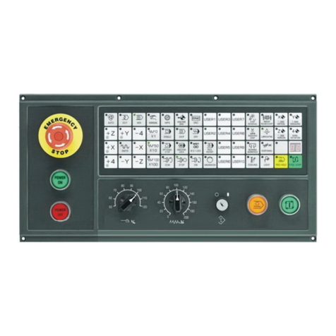
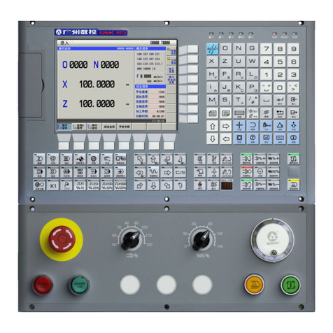
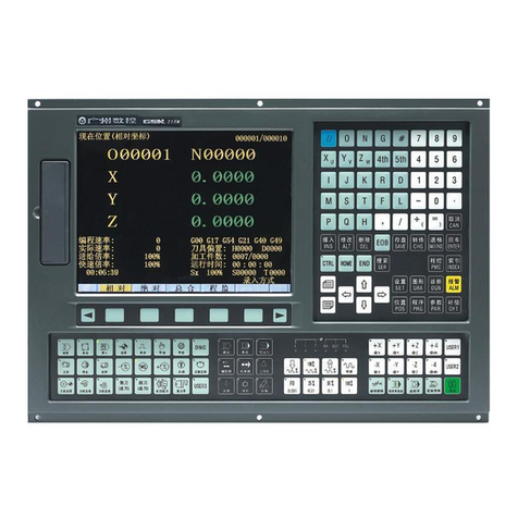
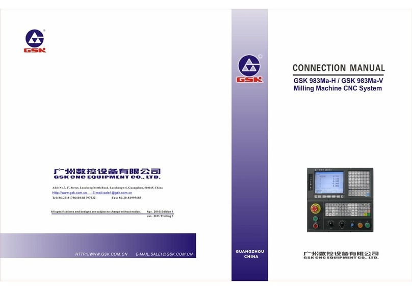
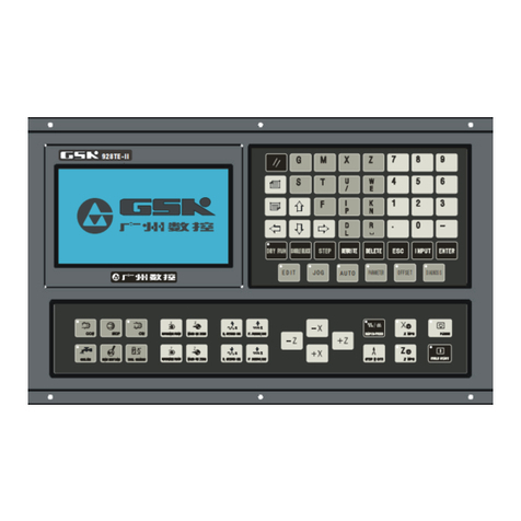
GSK 218M Instruction manual

RGB ELEKTRONIKA AGACIAK CIACIEK
SPÓŁKA JAWNA
Jana Dlugosza 2-6 Street
51-162 Wrocław
Poland
biuro@rgbelektronika.pl
+48 71 325 15 05
www.rgbautomatyka.pl
www.rgbelektronika.pl
DATASHEET
www.rgbautomatyka.pl
www.rgbelektronika.pl
OTHER SYMBOLS:
130SJT-M075D
130SJTM075D, 130SJT M075D, 130SJT-M075D
GSK

YOUR
PARTNER IN
MAINTENANCE
At our premises in Wrocław, we have a fully equipped servicing facility. Here we perform all the repair
works and test each later sold unit. Our trained employees, equipped with a wide variety of tools and
having several testing stands at their disposal, are a guarantee of the highest quality service.
OUR SERVICES
ENCODERS
SERVO
DRIVERS
LINEAR
ENCODERS
SERVO AMPLIFIERS
CNC
MACHINES
MOTORS
POWER
SUPPLIERS
OPERATOR
PANELS
CNC
CONTROLS
INDUSTRIAL
COMPUTERS
PLC
SYSTEMS
Repair this product with RGB ELEKTRONIKA ORDER A DIAGNOSIS ∠
Buy this product at RGB AUTOMATYKA BUY ∠

GSK 218M CNC System
Connection and PLC Manual

GSK218M CNC System Connection and PLC Manual
1
The user manual describes all items concerning the operation
of this CNC system in detail as much as possible. However, it’s
impractical to give particular descriptions for all unnecessary and/or
unavailable operations on the motor due to the limit of the manual,
specific operations of the product and other causes. Therefore, the
operations not specified in this manual may be considered impossible
or unallowable.

GSK218M CNC System Connection and PLC Manual
2
This manual is the property of GSK CNC Equipment Co., Ltd. All
rights reserved. It is against the law for any organization or individual to
publish or reprint this manual without the express written permission of
GSK CNC Equipment Co., Ltd. and the latter reserves the right to
ascertain their legal liability.

GSK218M CNC System Connection and PLC Manual
3
Company profile
GSK——GSK CNC Equipment Co,. Ltd is the largest production and marketing enterprise of
the CNC system in China currently. It is the Numerical Control industrial base of South China, and
the undertaking enterprise of the 863 national main project Industrialization Support Technology for
Medium Numerical Control System as well as one of the 20 basic equipment manufacture
enterprises in Guangdong province. It has been taking up the research and development, design
and the manufacture of machine CNC system (CNC device, drive unit and servo motor) in recent
10 years. Now it has developed into a large high-tech enterprise integrated with research,
education, industry and trade by enhancing the popularization and trade of CNC machine tools.
There are more than 1400 staffs in this company that involves 4 doctors, more than 50 graduate
students and 500 engineers and more than 50 among them are qualified with senior technical post
titles. The high performance-cost ratio products of GSK are popularized in China and Southeast
Asia. And the market occupation of GSK’s product dominates first and the turnout and sale ranks
the top in internal industry for successive 7 years from the year 2000 to 2006, which makes it the
largest CNC manufacture base throughout China.
The main products provided by our company includes the NC equipments and devices such as
GSK series turning machine, milling machine, machining center CNC system, DA98, DA98A,
DA98B, DA98D series full digital stepper motor drive device, DY3 series compound stepper driver
device, DF3 series response stepper motor driver device, GSK SJT series AC servo motors, CT-L
NC slider and so on. The current national standard (and international standard), industry standard,
as well as the enterprise standard (or enterprise internal standard) as a supplementary, are
completely implemented in our production process. The capability of abundant technology
development and complete production and quality system qualified by us will undoubtedly ensure
the reliable product to serve our customers. 24~48 hours technological support and service can be
easily and promptly provided by our complete service mechanism and tens of service offices
distributed in provinces around China and abroad. The pursuit of “excellent product and
superexcellent service” has made the GSK what it is now, and we will spare no efforts to continue
to consummate this South China NC industry base and enhance our national NC industry by our
managerial concept of “century enterprise, golden brand”.

GSK218M CNC System Connection and PLC Manual
4
Technological Spot Service
You can ask for spot service if you have the problems that can’t be solved by telephone. We will
send the engineers authorized to your place to resolve the technological problems for you.
Foreword
Dear user,
It’s our pleasure for your patronage and purchase of this GSK GSK218M CNC system made by
GSK CNC Equipment Co., Ltd.
The manual is “Connection and PLC Manual”.
!Accident may occur by improper connection and operation!This system can only be
operated by authorized and qualified personnel. Please carefully read this manual
before usage!
This manual is reserved by final user.
All specifications and designs herein are subject to change without further notice.
We are full of heartfelt gratitude to you for supporting us in the use of GSK’s products.

GSK218M CNC System Connection and PLC Manual
5
Warning and precautions
Warning, notice and explanation
This manual contains the precautions to protect user and machine. The precautions are classified
as warning and notice by safety, and supplementary information is regarded as explanation. Read
the warnings, notes and explanations carefully before operation.
Warning
User may be hurted or equipment can be damaged if operations and steps are not observed.
Notice
Equipment may be damaged if operation instructions or steps are not observed by user.
Explanation
It is used for the supplementary information except for warning and notice.
zCopy right is reserved.

GSK218M CNC System Connection and PLC Manual
6
Contents
VOLUME ONE PROGRAMMING................................………..12
1SEQUENCE PROGRAM CREATING PROCESS.......................................... 13
1.1 GSK218M PLC specification........................................................................................................13
1.2 What is a sequence program.........................................................................................................13
1.3 Establishment of interface specifications
(
step 1
)
...................................................................14
1.4 Establishment of ladder diagram
(
step 2
)
................................................................................14
1.5 Sequence program check
(
step 3
)
............................................................................................14
2SEQUENCE PROGRAM......................................................................... 15
2.1 Execution process of sequence program.....................................................................................15
2.2 Repetitive cycel................................................................................................................................16
2.3 Priority of execution(1st level, and 2nd level).................................................................................16
2.4 Sequence program structure..........................................................................................................17
2.5 Processing I/O (input/output) signals............................................................................................19
2.5.1 Input signal processing ...........................................................................................................................20
2.5.2 Output singal processing........................................................................................................................20
2.5.3 Syncrhonous processing short pulse signal .....................................................................................20
2.5.4 Difference o fstate of signals between 1st level and 2nd level.........................................................21
2.6 Interlocking..........................................................................................................................................22
3ADDRESS........................................................................................... 23
3.1 Addresses from Machine tool to PLC
(
X
)
...................................................................................23
3.1.1 Assignment of IO module X address....................................................................................................23
3.1.2 Assignment of MDI panel X address................................................................................................... 24
3.2 Address (Y) from PLC to machine tool...........................................................................................25
3.2.1 Assignment of IO module Y address...................................................................................................25
3.2.2 Assignment of IO module Y address....................................................................................................26
3.3 Address (G) from PLC to CNC.......................................................................................................27
3.4 Address (F) from CNC to PLC.......................................................................................................28
3.5 Internal relay address
(
R
)
...........................................................................................................29
3.6 Address of keep relay
(
K
)
...........................................................................................................29
3.7 Addresses(A) for message selection displayed on CRT............................................................29
3.8 Address of meter
(
C
)
...................................................................................................................30
3.9 Meter preset address(DC) ...............................................................................................................30
3.10 Timer addresses
(
T
)
....................................................................................................................30
3.11 Addresses of timer preset value
(
DT
)
.......................................................................................30
3.12 Address of data table
(
D
)
............................................................................................................31
3.13 Lable address
(
L
)
.........................................................................................................................31
3.14 Subprogram numbers
(
P
)
...........................................................................................................31
4PLC BASIC INSTRUCTION.................................................................. 32
4.1 RD, RD.NOT, WRT, WRT.NOT........................................................................................................33
4.2 AND, AND.NOT instructions.............................................................................................................33
4.3 OR, OR.NOT instructions.................................................................................................................34
4.4 OR. STK instruction...........................................................................................................................34

GSK218M CNC System Connection and PLC Manual
7
4.5 AND.STK instruction..........................................................................................................................35
5PLC FUNCTIONAL INSTRUCTIONS ........................................................ 36
5.1 END1
(
1st level sequence program end
)
..................................................................................37
5.2 END2
(
2nd level sequence program end
)
.................................................................................37
5.3 CALL
(
call subprogram
)
..............................................................................................................37
5.4 SP
(
Subprogram
)
.........................................................................................................................38
5.5 SPE
(
subprogram end
)
...............................................................................................................38
5.6 SET
(
set
)
.......................................................................................................................................39
5.7 RST
(
reset
)
...................................................................................................................................39
5.8 JMPB
(
label jump
)
.......................................................................................................................40
5.9 LBL
(
Label
)
...................................................................................................................................40
5.10 TMR
(
timer
)
..................................................................................................................................41
5.11 CTR
(
binary counter
)
...................................................................................................................42
5.12 DEC
(
binary decode
)
..................................................................................................................43
5.13 COD
(
binary code conversion
)
..................................................................................................44
5.14 COM (common line control)...........................................................................................................46
5.15 COME (common line control end).................................................................................................47
5.16 ROT
(
Binary rotation control
)
.....................................................................................................48
5.17 SFT
(
shift register
)
.......................................................................................................................50
5.18 DIFU
(
rising edge check
)
............................................................................................................51
5.19 DIFD
(
falling edge check
)
...........................................................................................................52
5.20 COMP
(
binary comparison
)
........................................................................................................53
5.21 COIN
(
concidence check
)
..........................................................................................................54
5.22 MOVN
(
transfer of data
)
.............................................................................................................55
5.23 XMOV
(
Binary index data transfer
)
...........................................................................................56
5.24 DSCH
(
binary data search
)
......................................................................................................57
5.25 ADD
(
addition
)
..............................................................................................................................58
5.26 SUB
(
binary subtraction
)
............................................................................................................60
5.27 ANDF
(
logical and
)
......................................................................................................................61
5.28 ORF
(
logical or
)
............................................................................................................................62
5.29 NOT
(
logical not
)
..........................................................................................................................63
5.30 EOR
(
exclusive or
)
......................................................................................................................64
6LADDER WRITING LIMIT....................................................................... 66
VOLUME TWO FUNCTION........................................................67
1CONTROLLED AXIS ............................................................................. 68
1.1 Outputting of movemtn state of an axis........................................................................................68
1.2 Servo ready signal...........................................................................................................................69
1.3 Servo OFF signal.............................................................................................................................69
1.4 Mirror image......................................................................................................................................71
1.5 Position switch....................................................................................................................................73
2PREPARATION FOR OPERATION ........................................................... 74
2.1 Emergency stop...............................................................................................................................74
2.2 CNC ready signal.............................................................................................................................74
2.3 CNC overtravel signal .....................................................................................................................75

GSK218M CNC System Connection and PLC Manual
8
2.4 Alarm signal......................................................................................................................................76
2.5 Machine ready signal......................................................................................................................77
2.6 Interlock activation...........................................................................................................................77
2.7 Mode selection.................................................................................................................................78
2.8 Status output signal.........................................................................................................................78
2.9 VRDY OFF alarm ignore signal .....................................................................................................79
2.10 Abnormal load check.......................................................................................................................79
3MANUAL OPERATION .......................................................................... 81
3.1 JOG feed/incremental feed.............................................................................................................81
3.2 MPG(Handwheel) feed....................................................................................................................82
3.3 MPG interruption..............................................................................................................................83
4REFERENCE POINT RETURN ................................................................ 84
4.1 Manual reference point return........................................................................................................84
5AUTOMATIC OPERATION...................................................................... 88
5.1 Cycle start/feed hold........................................................................................................................88
5.2 Reset..................................................................................................................................................91
5.3 Testing a program............................................................................................................................93
5.3.1 Machine tool lock.....................................................................................................................................93
5.3.2 Dry run..........................................................................................................................................................94
5.3.3 Single block ..............................................................................................................................................95
5.4 Optional block skip...........................................................................................................................96
5.5 Program restart ................................................................................................................................97
6INTERPOLATION FUNCTION .................................................................. 98
6.1 Thread cutting...................................................................................................................................98
7FEEDRATE CONTROL .......................................................................... 99
7.1 Rapid traverse rate..........................................................................................................................99
7.2 Advanced preview control...............................................................................................................99
7.3 In-position check............................................................................................................................100
7.4 Error detect.....................................................................................................................................101
7.5 Override...........................................................................................................................................102
7.5.1 Rapid traverse override........................................................................................................................ 102
7.5.2 Feedrate override................................................................................................................................... 102
7.5.3 Override cancel...................................................................................................................................... 103
8MISCELLANEOUS FUNCTION (M, S, TFUNCTION)................................. 104
8.1 Miscellaneous function..................................................................................................................104
8.2 Auxiliary function lock....................................................................................................................109
8.3 High-speed M/S/T interface..........................................................................................................110
9SPINDLE SPEED FUNCTION................................................................ 113
9.1 Spindle speed control mode.........................................................................................................113
9.1.1 Gear spindle............................................................................................................................................ 113
9.1.2 Analog spindle ....................................................................................................................................... 114
9.2 Spindle speed arrival signal.........................................................................................................115
9.3 Constant surface speed control...................................................................................................116
9.4 Rigid tapping...................................................................................................................................117

GSK218M CNC System Connection and PLC Manual
9
10 TOOL FUNCTION ............................................................................. 119
10.1 T instruction executing tool change...........................................................................................119
10.2 Tool life management....................................................................................................................119
11. PROGRAMMNG INSTRUCITON .......................................................... 123
11.1 Custom macro program ..............................................................................................................123
11.2 Cannedcycle................................................................................................................................126
11.3 Metric/Inch conversion ................................................................................................................127
11.4 Small hole peck drilling cycle.....................................................................................................128
12 DISPLAY/SET ................................................................................. 129
12.1 Clock Function .............................................................................................................................129
12.2 Displaying operation history.......................................................................................................129
12.3 Help function.................................................................................................................................129
12.4 Operation hour and parts count display .....................................................................................129
12.5 Memory protection key................................................................................................................130
13 MEASUREMENT .............................................................................. 132
13.1 Skip function...................................................................................................................................132
13.2 Torque limit skip...........................................................................................................................133
APPENDIX........................................................................................... 134
Signal list (During order of address).......................................................................................................134
VOLUME THREE OPERATION .................................................137
1PLC INTERFACE DISPLAY ................................................................. 138
1.1 Automatic operation when GSK218M PLC power on ..............................................................138
1.2 INFO interface display...................................................................................................................138
1.2.1 INFO interface......................................................................................................................................... 138
1.2.2 PLCGRA interface.................................................................................................................................. 139
1.2.3 PLCPAR interface ............................................................................................................................... 139
1.2.4 PLCGND interface .................................................................................................................................140
2PLC PROGRAMMING OPERATION....................................................... 142
2.1 General............................................................................................................................................142
2.2 Basic instruction(B. INST).............................................................................................................143
2.3 Operations of ladder......................................................................................................................144
2.4 Function instruction........................................................................................................................146
2.5 Instruction list..................................................................................................................................148
2.6 Edit instruction................................................................................................................................149
2.7 PLC operation step........................................................................................................................150
3PLC ADDRESS,PARAMETER SETTING ............................................... 151
3.1 Counter..............................................................................................................................................151
3.2 Timer................................................................................................................................................152
3.3 Data list............................................................................................................................................153
3.4 Keep relay.......................................................................................................................................154
3.5 F address corresponded to M function.......................................................................................155
VOLUME FOUR CONNECTION................................................157

GSK218M CNC System Connection and PLC Manual
10
1SYSTEM STRUCTURE AND INSTALLATION............................................ 158
1.1 System composition...........................................................................................................................158
1.2 System installtion & connection........................................................................................................158
1.3 CNC system installation dimension..................................................................................................159
2DEVICE CONNECTION........................................................................ 162
2.1 CNC external connection...................................................................................................................162
2.2.1 System interface......................................................................................................................................... 162
2.2.2 Interface signal list..................................................................................................................................... 163
2.2.3 Signal specification ................................................................................................................................... 163
2.2.4 Cable connection .......................................................................................................................................... 166
2.3 RS232 standard serial interface ....................................................................................................167
2.4 MPG(handwheel), hand unit connection.........................................................................................167
2.4.1 Interface signal list..................................................................................................................................... 167
2.4.2 Interface signal............................................................................................................................................ 167
2.5 Spindle unit connection......................................................................................................................168
2.5.1 Interface signal list..................................................................................................................................... 168
2.5.2 Interface signal: ....................................................................................................................................... 168
2.6 Power supply interface.......................................................................................................................168
3MACHINE CONTROL I/O INTERFACE ................................................... 169
3.1 Interface signal list..............................................................................................................................169
3.2 Input interface......................................................................................................................................169
3.2.1 Input interface method.............................................................................................................................. 169
3.2.2 Input signal interface definition.............................................................................................................. 170
3.3 Output signal .......................................................................................................................................172
3.3.1 Output interface method...........................................................................................................................172
3.3.2 Ouput signal interface definition............................................................................................................173
4DEBUGGING MACHINE....................................................................... 175
4.1 Debug preparation..............................................................................................................................175
4.2 System power on................................................................................................................................175
4.3 Emergency stop and limit..................................................................................................................176
4.4 Gear ratio adjustment.........................................................................................................................177
4.5 Backlash compensation.....................................................................................................................178
4.6 Parameter for servo............................................................................................................................179
4.7 Machine pitch compensation.............................................................................................................179
4.8 Debugging parameters ......................................................................................................................182
4.8.1 Machine zero return................................................................................................................................... 182
4.9 Input/output signal control of spindle CW/CCW....................................................................................183
4.10 Spindle automatic gear change control................................................................................................. 184
4.11 External cycle start and feed hold........................................................................................................... 186
4.12 Cooling, lubricant and chip removal control........................................................................................ 186
4.13 Parameters of axis control........................................................................................................................ 187
4.14 Parameter for coordinate system............................................................................................................ 188
4.15 Parameter for feedrate ............................................................................................................................... 188
4.16 Parameters for MDI, display and servo.................................................................................................. 191
4.16 Parameters of MDI, display and edit....................................................................................................... 191

GSK218M CNC System Connection and PLC Manual
11
4.17 Parameters for tool compensation.......................................................................................................... 194
APPENDIX:....................................................................................... 196
Guide for GSK218M matching with ladder............................................................................................196
1. Notices of GSK218M matching with turret tool magazine ............................................................................ 196
2. Allocation and definition of PMC IO address, auxiliary relay and register.................................................. 196
3. Usage and maintenance of GSK 218M CNC System matching with turret tool magazine .....................218
4. Macro program statement of GSK218M CNC System matching with turret tool magazine .................... 223

GSK218M CNC System Connection and PLC Manual
12
Volume one Programming

GSK218M CNC System Connection and PLC Manual
13
1 Sequence Program Creating Process
1.1 GSK218M PLC specification
Specifications of GSK218M PLC are as follows:
1.2 What is a sequence program
A sequence program is a programm for sequence control of machine tools and other
systems.
The program is converted into a format to enable CPU execute encoding and arithmetic
processing, and stored into RAM. CPU reads out instructions of the program stored into the
memory at the high-speed every instruction and execute the program by arithmetic operation
The sequence program is written firstly from ladder. 。
Specification GSK218M PLC
Programming method language Ladder
Number of ladder level 2
1st level execution period 8ms
Mean processing time of basic instruction 10μs
Program capacity 4700 step
Instruction Basic instruction +function
instruction
Internal relay (R)
PLC message request (A)
Keepmemory
* Timer (T)
* Meter (C)
* Data table (D)
* Keep relay (K)
* Meter preset value data register (DC)
* Timer preset value data register (DT)
Subprogram (P)
Label (L)
0~511 byte
0~31 byte
0~127 byte
0~127 byte
0~255 byte
0~63 byte
0~127 byte
0~127 byte
0~99
0~99
I/O module(X)
(Y)
0~63 byte
0~47 byte

GSK218M CNC System Connection and PLC Manual
14
1.3 Establishment of interface specifications(step 1)
After deciding the control object specification and calculate the number of input/output signal
points, creat the interface specification.
For input/output interface signals, see Chapter 4.
1.4 Establishment of ladder diagram(step 2)
Express the control operations decided by 218M ladder diagram. For the timer, meter, etc, which
cannot be expressed with the functional instructions.
The edited ladder should be converted into the corresponding PLC instruction to store.
1.5 Sequence program check(step 3)
The sequence program can be checked in two ways:
1)Check by simulator
Instead of the machine, connect a simulator (consisting of lamps and switchs). Switch
ON/OFF stands for the input signal state of machine, lamp ON/OFF for the output signal
state.
2)Actual operation debugging
Debug sequence program through operating the machine. Do measures against the
unexpected affairs before debugging.

GSK218M CNC System Connection and PLC Manual
15
2 Sequence Program
Since PLC sequence control handled by software and operates on principle difference from a
general relay circuit, the sequence control method must be fully understood in order to design PLC
sequence program.
2.1 Execution process of sequence program
In general relay control circuit, each relay operates at approximately the same time, in the figure
below for example, when relay A operatre, the relay D and E operate at approximately the same
time(when contacts B and C are off)., In PLC sequence control, each relay of circuit operates
sequenctially. When relay A operates, relay D operates, then relay E(see the below figure). Thus
each relay operates in sequence which can be written as a ladder diagram. (programmed
sequence).
Fig. 2.1(a) circuit example
Fig.(b) and (c) illustrate operations varying from the relay circuit to PLC program.
Fig.2.1(b)
Fig.2.1(c)
A
A C
D
E
B
A C
A
B
C
A
A
C
B
C

GSK218M CNC System Connection and PLC Manual
16
(1) Relay circuit
In Fig. (A) and (B), the operations are the same. Turning on A turns on B and C. Turning on C
turns off B.
(2) 218M PLC program
In Fig.(B), as in the relay circuit, turning on A turns on B and C, and after one cycle of the PLC
sequence, turns off B. But in Fig.(C), turning on A turns on C, but does not turn on B.
2.2 Repetitive cycel
The sequence program is executed from the beginning of coding to the end of coding of the ladder
diagram in the sequence written. When the seqeuence program ends, the program starts over
form the beginning. This is called repetitive operation.
The execution time from the beginning to the end of the ladder diagram is called the sequence
processing time. The shorter the process time is, the better the signal response becomes.
2.3 Priority of execution(1st level, and 2nd level)
GSK218M PLC consists of two parts: 1st level sequence part, 2nd level sequence part. They have
different execution period.
The 1st level sequence part operates every 4ms, which can operate the short pulse signal with
high-speed response).
The 2nd level sequence part operates every 4*n ms. Here n is a dividing number for the 2nd level
sequence part. The 2nd level sequence part is divided into n part, and every part is executed every
4ms.

GSK218M CNC System Connection and PLC Manual
17
218M PLC is solely executed in PLC-AVR single unit, and the second 2ms of every 4ms is the
communication time of CNC reading or writing PLC data.
After the last 2nd level sequence part (division n) is executed, the sequence program is executed
again from the beginning. Thus, when the dividing number is n, the cycle of execution is 4*n ms.
The 1st level sequence operates every 4ms, and the 2nd level sequence every 4*n ms. If the steps
of the 1st level sequence is increased, the steps of the 2nd level sequence operating within 4ms
becomes less, thereby increasing the dividing number and making the processing time longer.
Therefore, it is desirable to program so as to reduce the 1st level sequence to a minimum.
2.4 Sequence program structure
With the conventional PLC, a ladder program is described sequentially. By employing a ladder
language that allows structured programming, the follwing benefits are derived:
1. A program can be understood and developed easily
2. A program error can be found easily.
END2
END1
1st level
sequence part
2nd level
sequence program
Specifies the end of the
1st level sequence part
Division 1
Division 2
Division n
Specifies the end of the
2nd level sequence part
4
Division 1
1st level
2nd level
CNC processing
144
1
Division 2
1
Division n 7
Table of contents
Other GSK Control System manuals