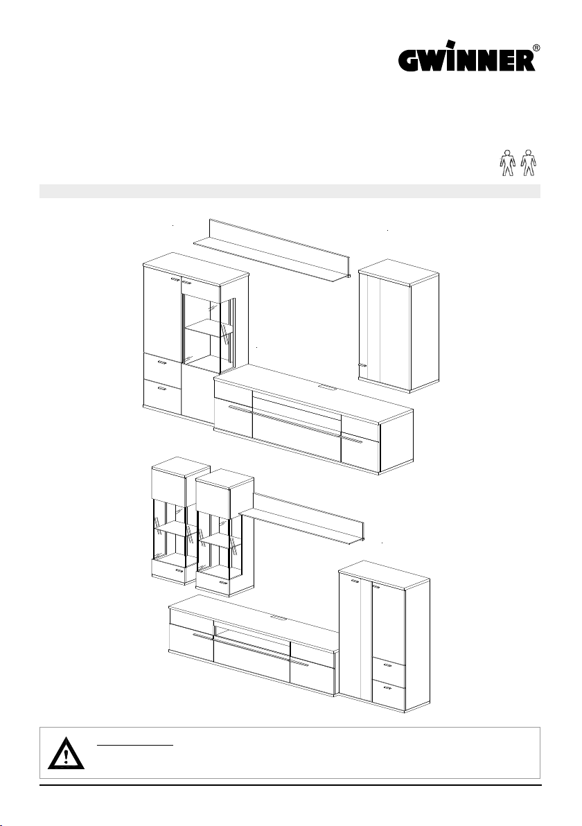
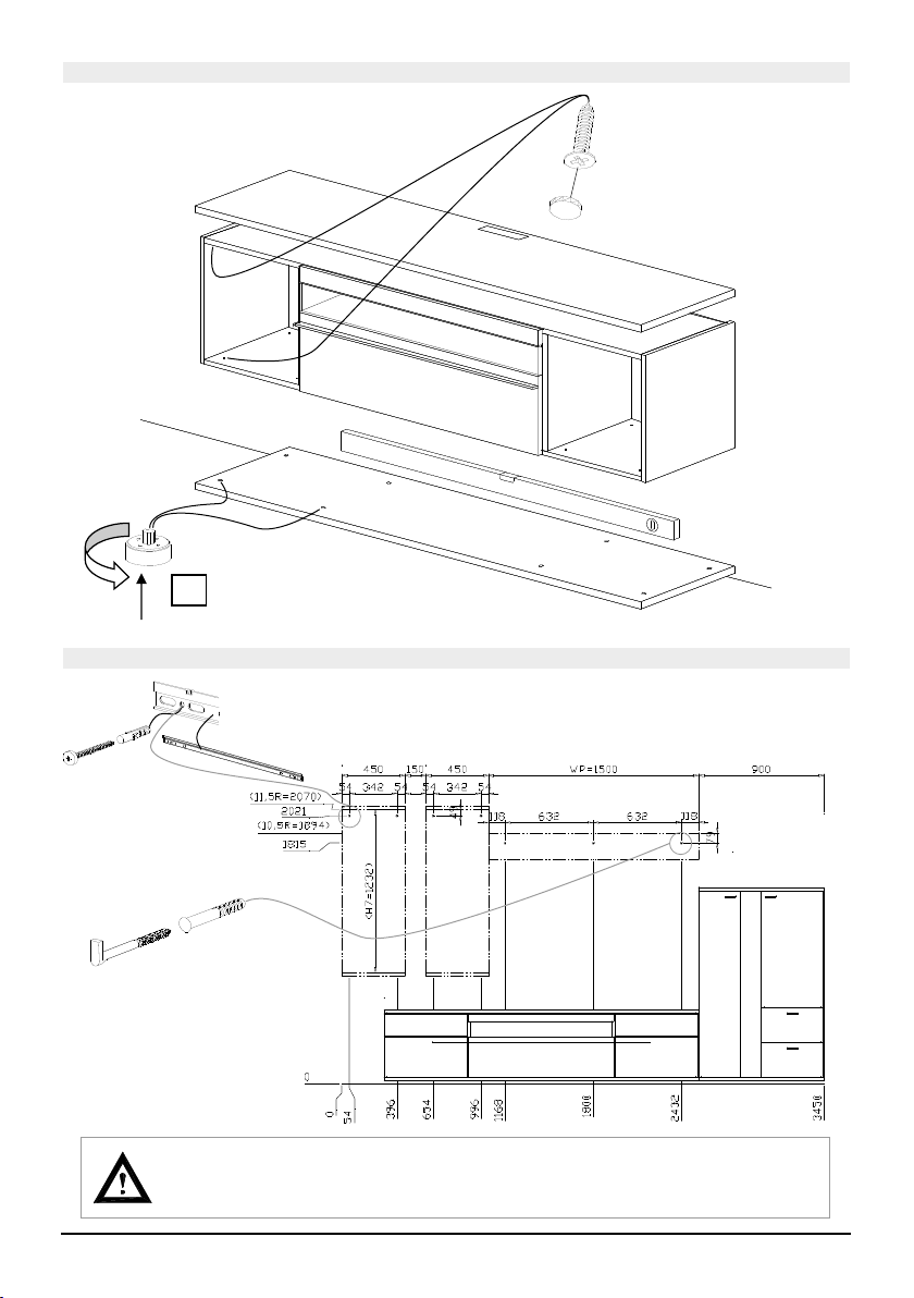
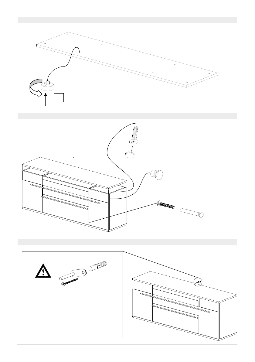
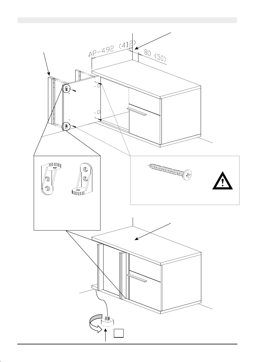
GWINNER ATENA Configuration guide

1GENERAL ATENA | FIERA ASSEMBLY
GENERAL ASSEMBLY
ATENA | FIERA
IMAGE 1, Example walls AT2 and AT4
Qualied pecialist personnel
PLEASE NOTE:
CAUTION!

+/-
2GENERAL ATENA | FIERA ASSEMBLY
IMAGE 2,
Push the levelling gliders into the
intended holes and align the cabinets
Wall plug,
dia. 8 mm
4x17 fillister-
head screw
5.5x70 cylinder-head
screw
On all 5-8-increment U cabinets, a fixing
bracket with metal pegs is fitted as an
anti-tip mechanism. To do so, use a
5x60mm countersunk screw and a plastic
wall plug (dia. 8 mm). The
panel only covers the fittings when fitted at
an angle.

+/-
+/-
3GENERAL ATENA | FIERA ASSEMBLY
IMAGE
IMAGE
Connecting screw
M4x 28 with sleeve nut
Secure the 26-mm cover panels at the
marked points from the interior.
4x27 mm countersunk screw and cover
caps
Secure the 19 mm cover
panels at the marked points
from the interior.
4x27 mm countersunk screw
and cover caps
Push the levelling gliders into the
intended holes and align the cabinets.
If necessary, remove the fronts
Push the levelling gliders into the
intended holes and align the cabinets.
If necessary, remove the fronts

4GENERAL ATENA | FIERA ASSEMBLY
IMAGE 5,
IMAGE
5.5x70 cylinder-head screw
+ 8-mm wall plug
Drill 3x 8-mm wall
plug and screw
in the wall hook
The wall plugs supplied are suitable for the following sub-surfaces:
Concrete, solid brick, ventilating brick, hollow concrete blocks.
If there is a different sub-surface, select an appropriate fixing material
Hanging the
wall unit
Cover cap,
d= 12mm
(4x27 mm countersunk
screw and cover caps in the
carcase colour)
Upper adjustment screw
= depth adjustment
Lower adjustment screw
= height adjustment

5GENERAL ATENA | FIERA ASSEMBLY
IMAGE
IMAGE
"
Glue the LED strip to the glass from below.
2
Cut the LED strip
e.g. to 1600 mm for
1650-mm wall panel
1
+/-
+/-
2
3
1
Adjusting
wall panels
Hanging the wall panel
Adjust the angle of
the wall panel using a
spanner wrench (AF 8)
+/-
+/-

6GENERAL ATENA | FIERA ASSEMBLY
IMAGE 9,
"
2
1
3
Slide the front panel
to the left
If requested by the customer,
adhere the LED lighting (self-
adhesive); cut to size if necessary,
e.g. 950 or 650 mm and
Cut the LED strip e.g. to 950 mm
for 1050-mm front panels
„LN75“ lighting measuring 65 cm
behind 75-cm front panel
„LN105“ lighting measuring 95 cm
behind 105-cm front panel
Secure the cable using a
clip and lay the lighting cables in
the carcase.

7GENERAL ATENA | FIERA ASSEMBLY
+/-
Secure the 19 mm cover
panels at the marked points
from the interior.
4x27 mm countersunk
screw and cover caps
Push the levelling gliders into the
intended holes and align the cabinets.
If necessary, remove the fronts
IMAGE
5.5x70 cylinder-head screw
+ 8-mm wall plug
Drill 3x 8-mm wall
plug and screw in
the wall hook
The wall plugs supplied are suitable for the following sub-surfaces:
Concrete, solid brick, ventilating brick, hollow concrete blocks.
If there is a different sub-surface, select an appropriate fixing material
IMAGE 11,

8GENERAL ATENA | FIERA ASSEMBLY
+/- Push the levelling gliders into the
intended holes and align the cabinets
IMAGE 12,
IMAGE 13
IMAGE 14,
(4x27 mm countersunk screw and cover
caps in the carcase colour)
Nickel-plated cover cap
dia. 5 mm; fit to any
unused connecting holes
in cabinet sides.
Connecting screw
M4x 28 with sleeve nut
On all 5-8-increment U cabinets, a fixing
bracket with metal pegs is fitted as an
anti-tip mechanism. To do so, use a
5x60mm countersunk screw and a plastic
wall plug (dia. 8 mm). The
panel only covers the fittings when fitted
at an angle.

9GENERAL ATENA | FIERA ASSEMBLY
IMAGE 15,
Wooden strip with
front lacquered
panel
Cover panel overhang of
80 mm on cover panels
less than 492 mm, 50-mm
overhang on cover panel
less than 412 mm deep
Fit 2x angle brackets each
with 2x Seko 3.5 x 13
+ 1x Liko 4x 20 screws
for safety.
Secure wooden strip with 4x
40 mm plate screws at marked
points.
+/- Push the levelling gliders into the intended
holes and align the cabinets

10 GENERAL ATENA | FIERA ASSEMBLY
IMAGE
5x 8-mm wall plug
and screw in the wall
hook
Fit the aperture angle
limiter to the strip.

11GENERAL ATENA | FIERA ASSEMBLY
IMAGE 17,
Secure the hinge to the door Hang the door
Hanging the doors
The aperture angle limiter 74.1103 is used for all 107° hinges and limits the aperture angle
to 86°.
Step 1: The aperture angle limiter can only be fitted when the hinge has not yet been fitted to the
door. Then close the hinge by around 45°.
Step 2: You can then push the aperture angle limiter into the opening on the underside until
it audibly clicks into place.
Step 3: Once you have subsequently fitted the hinge to the door and connected it to the
carcase, the aperture angle is limited to 86°.
CLIP top BLUMOTION
Remove the hinge from
the door
2
6
3
4
1
5

12 GENERAL ATENA | FIERA ASSEMBLY
2
1
IMAGE 18,
IMAGE 19,
Drill the 8-mm wall
plug and screw in
the wall hook
The wall plugs supplied are suitable for the following sub-surfaces:
Concrete, solid brick, ventilating brick, hollow concrete blocks.
If there is a different sub-surface, select an appropriate fixing material
Glass shelves
Wall panel
Slide the glass
shelf into the wall
panel
Hinten
+/-
SW 5
+/-
SW 5
AT312 I AT412

Drill the 8-mm wall plug
and screw in the wall hook
The wall plugs supplied are suitable for the following sub-surfaces:
Concrete, solid brick, ventilating brick, hollow concrete blocks.
If there is a different sub-surface, select an appropriate fixing material
13GENERAL ATENA | FIERA ASSEMBLY
IMAGE 20,
IMAGE 21,
Slide the glass shelf
into the wall panel
AT301
Glass shelves
Wall panel
2
1
+/-
SW 5
+/-
SW 5

14 GENERAL ATENA | FIERA ASSEMBLY
IMAGE 22,
IMAGE 23,
2
1
4x plate screw 5x20
+ U-Scheibe
4x 5x80 countersunk screw
+ wall plug dia. 8 mm
Hanging the
wall unit
Cover cap,
d= 12mm
(4x27 mm countersunk
screw and cover caps in the
carcase colour)
Upper adjustment screw
= depth adjustment
Lower adjustment screw
= height adjustment

The wall plugs supplied are suitable for the following sub-surfaces:
Concrete, solid brick, ventilating brick, hollow concrete blocks.
If there is a different sub-surface, select an appropriate fixing material
Drill the 8-mm
wall plug and
screw in the wall
hook
15GENERAL ATENA | FIERA ASSEMBLY
IMAGE 24,
IMAGE 25,
Fixing frame with 14x
countersunk screw
Ø5x80 mm
4x set screw M8x18 mm for
height adjustment!
+ 4x Felt Ø15x3 mm
Connection of frame
parts with 8x countersunk
screw M8x25 mm black
1
3
2
AT306
+/-
SW 5

The wall plugs supplied are suitable for the following sub-surfaces:
Concrete, solid brick, ventilating brick, hollow concrete blocks.
If there is a different sub-surface, select an appropriate fixing material
16 GENERAL ATENA | FIERA ASSEMBLY
IMAGE 26,
IMAGE 27,
5.5x70 cylinder-head screw
+ 8-mm wall plug
Drill 3x 8-mm wall
plug and screw in the
wall hook
Hanging the
wall unit
Cover cap,
d= 12mm
Upper adjustment screw
= depth adjustment
Lower adjustment screw
= height adjustment
AT303
(4x27 mm countersunk
screw and cover caps in the
carcase colour)

17GENERAL ATENA | FIERA ASSEMBLY
WI120G
WI150G
WI165G
WI180G
WI195G
WI225G
The wall plugs supplied are suitable for the following sub-surfaces:
Concrete, solid brick, ventilating brick, hollow concrete blocks.
If there is a different sub-surface, select an appropriate fixing material.
Drill the 8-mm wall plug
and screw in the wall hook

18 GENERAL ATENA | FIERA ASSEMBLY
The wall plugs supplied are suitable for the following sub-surfaces:
Concrete, solid brick, ventilating brick, hollow concrete blocks.
If there is a different sub-surface, select an appropriate fixing material.
5.5x70 cylinder-head screw
+ 8-mm wall plug
2x 125-mm rail for each cabinet

19GENERAL ATENA | FIERA ASSEMBLY
The wall plugs supplied are suitable for the following sub-surfaces:
Concrete, solid brick, ventilating brick, hollow concrete blocks.
If there is a different sub-surface, select an appropriate fixing material.
5.5x70 cylinder-head screw
+ 8-mm wall plug
1x 25-cm rail for each 30-cm cabinet,
1x 40-cm rail for each 45-cm cabinet,
1x 55-cm rail for each 60-cm cabinet,
2x 12.5-cm rails for 75- + 90-cm cabinets

20 GENERAL ATENA | FIERA ASSEMBLY
The wall plugs supplied are suitable for the following sub-surfaces:
Concrete, solid brick, ventilating brick, hollow concrete blocks.
If there is a different sub-surface, select an appropriate fixing material.
5.5x70 cylinder-head screw
and 8-mm wall plug
2x 25-cm rails for each 30-cm cabinet
5.5x70 cylinder-head screw
and 8-mm wall plug
2x 40-cm rails for each 45-cm cabinet,
2x 55-cm rails for each 60-cm cabinet
This manual suits for next models
3
Other GWINNER Indoor Furnishing manuals

GWINNER
GWINNER MISANO R5516 User manual

GWINNER
GWINNER CALEA User manual

GWINNER
GWINNER CALEA CE1003 User manual

GWINNER
GWINNER FELINO Instruction Manual

GWINNER
GWINNER MISANO User manual

GWINNER
GWINNER MEDIA CONCEPT User manual

GWINNER
GWINNER MEDIA CONCEPT SP67 User manual

GWINNER
GWINNER MEDIA CONCEPT MC969K User manual

GWINNER
GWINNER TREVISO User manual
Popular Indoor Furnishing manuals by other brands

Hay
Hay CAN SOFA instruction manual

Amart Furniture
Amart Furniture KHYBER 72840 Assembly instruction

Whalen
Whalen Axon Task WC-13AX-GO Instruction booklet

Universal Furniture
Universal Furniture 572850 instruction sheet

Forte
Forte DCMS712 Assembling Instruction

Grand PATIO
Grand PATIO BRETON quick start guide