manuals.online logo
Brands
  1. Home
  2. •
  3. Brands
  4. •
  5. GWINNER
  6. •
  7. Indoor Furnishing
  8. •
  9. GWINNER MEDIA CONCEPT MC969K User manual

GWINNER MEDIA CONCEPT MC969K User manual

1GENERAL MEDIA CONCEPT INSTALLATION
Qualied specialist personnel
IMAGE 1, Example walls MC969K, HB8-11, SB4-1
IMAGE 2, tting the anti-tip mechanism
On all 4-increment and 8-increment U
cupboards, a fixing bracket with metal
pins is fitted as an anti-tip mechanism.
A 5x60 mm countersunk screw and an
8-mm-dia. plastic wall plug is used
to do so. The 13-mm cover panel
only covers the fittings on angled
assemblies.
+/-
Push the levelling gliders
into the intended holes and
align the cupboards
Wall plug,
dia. 8mm
4x17
fillisterhead
screw
5.5x70
cylinderhead screw
GENERAL INSTALLATION
MEDIA CONCEPT
FROM R6150 ONWARDS
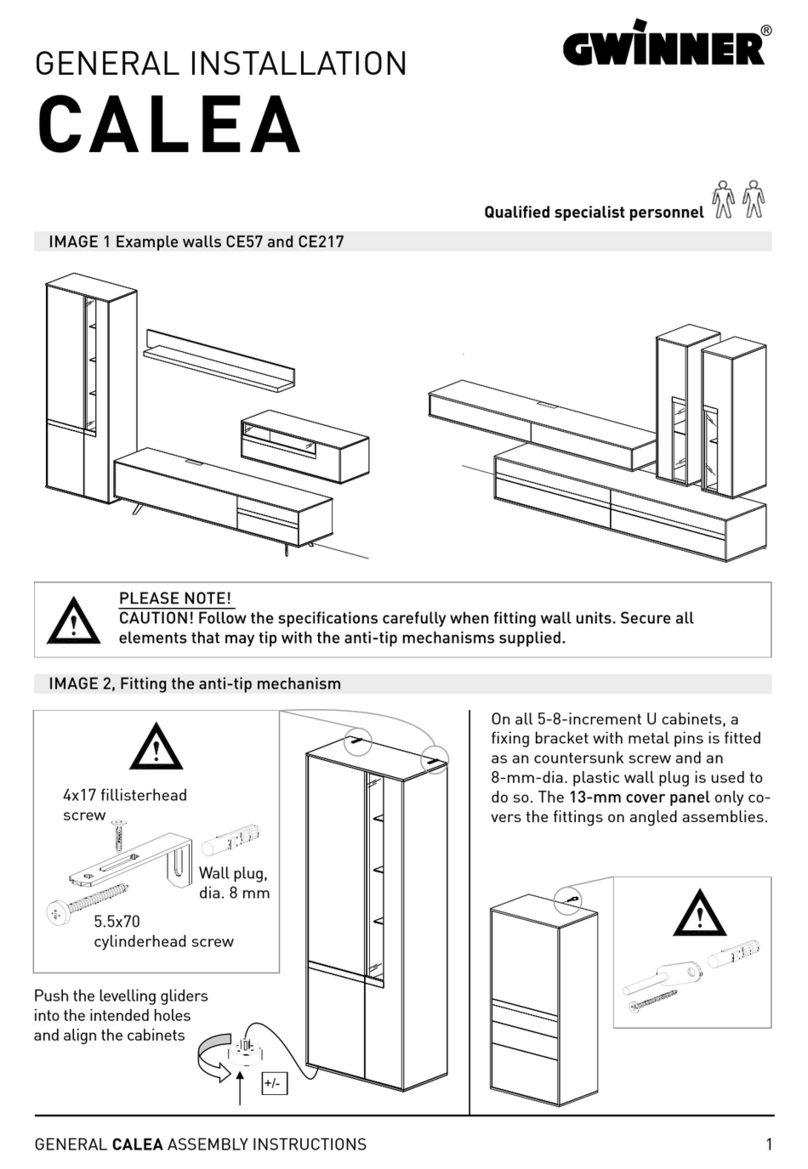
PLEASE NOTE!
CAUTION! Follow the specications carefully when tting wall units. Secure all
elements that may tip with the anti-tip mechanisms supplied.
+/-
+/-
2GENERAL MEDIA CONCEPT INSTALLATION
IMAGE 3, tting the cover panels and feet
IMAGE 4, pre-assembling the rear-panel cover pane
IMAGE 5, tting the leveling gliders on to the supporting sections
MC969K
Secure the 13-mm cover panels
at the marked points from the
inside. Use 4x27 mm countersunk
screws and cover caps
Push the levelling gliders into the
intended holes and align the cupboards,
removing the fronts if necessary
Push the levelling gliders into the
intended holes and align the cupboards,
removing the fronts if necessary
Screw the bottom rear panel
to the supporting section
panel using three Liko Spax
4x 50 screws
Rückwandaufsatz RWA
Position the custumer‘s multi-way socket
in the TV niche before assembling the cupboard
2x
3GENERAL MEDIA CONCEPT INSTALLATION
Six dia. 8x50
wooden
Connect the supporting section panel to the
supporting section side panel from below
using two Seko Spax 5x 80 screws
Connect the rear panel to the
supporting section panel and side
panel at a right angle!
Adjust the rear
panel in the
groove
2
1
The wall plugs supplied are suitable for the following sub-surfaces:
Concrete, solid brick, ventilating brick, hollow concrete blocks.
If there is a different subsurface, select an appropriate fixing material.
5.5x70 cylinder-head screw
and 8 mm wall plug
Drill dowels 8mm and
screw in wall hooks
Caution:
Take other
installation heights
and widths from the
measurements
system provided
IMAGE 6
IMAGE 7
IMAGE 8
IMAGE 9
4GENERAL MEDIA CONCEPT INSTALLATION
Upper adjustment screw
= depth adjustment
Lower adjustment screw
= height adjustment
Fit the glass sides
308 x 139 x 8 mm with buffer
„LN195“ light, only if
requested by the customer
(preassembled at the factroy
Fit four glass clamp fittings
at the marked points using
3x15 Liko screws
Secure the
cable with a
selfadhesive
cable clip
Secure the 13-mm cover
panels at the marked points
from the inside.
Use 4x27 mm countersunk
screws and cover caps
Two Rastex
screw-in dowels
Tighten the fittings
by turning them
Bild 8
Bild 9
Bild 9A, Montage LED-Band an obere Spangenplatte 33cm
MC969K
MC969K
Kabel mit
selbst-
klebendem
Kabelclip
befestigen
Leuchte "LN195",
nur bei KD-Wunsch
2x Einschraub-
dübel Rastex
Beschläge durch
drehen festziehen
Glasseiten 308x 139x 8mm
mit Puffer montieren
4x Glasklemmbeschlag an
markierten Punkten mit
Liko 3x 15 montieren
Befestigung Abdeckplatten 13mm an
markierten Punkten von innen!
Senkschraube 4x 27mm und Abdeck-
Kappen
untere Justierschraube =
Höhenverstellung
obere Justierschraube =
Tiefenverstellung
MC969K
Nut für Beleuchtungs-
Kabel
LED-Band abschneiden
z.B. 250mm bei
ob. Spangenplatte 325mm

Bei KD-Wunsch LED-Beleuchtung
aufkleben (selbstklebend),
Beidseitig Zugentlastung mit Liko
3x 13mm montieren!
LED-Band an markierten Punkten
befestigen!
. Montage MediaConcept allg.-ab R6150.xlsx 25.08.2022/EFF Seite 4/18
IMAGE 9A, Fitting the lighting in the upper chipboard 33 cm
MC969K
Adhere the LED lighting (self-
adhesive); Fit a strain relief on both
sides using Liko 3x13 mm
Fix the LED strip at the marked
point!
Cut the LED strip e.g. to 250 mm
for 325-mm chipboard
Slot for lighting cable
5GENERAL MEDIA CONCEPT INSTALLATION
Connect supporting
sectiont with cabinet
2x Seko 4x 70
Removable cable cover
with brush seal
Bild 9B, Montage LED-Band an obere Spangenplatte 176cm
Bild 10
MC969K
Kabelabdeckung mit
Bürstendichtung
zum herausnehemen
Spangen mit Schrank
verbinden
2x Seko 4x 70
MC969K
Nut für Beleuchtungs-
Kabel
Kabel mit Kabelclip
befestigen+
Beleuchtungskabel in
Korpus verlegen!
Bei KD-Wunsch LED-Beleuchtung
aufkleben (selbstklebend),
Beidseitig Zugentlastung mit Liko
3x 13mm montieren!
LED-Band an markierten Punkten
befestigen!
LED-Band abschneiden
z.B. 1700mm bei
ob. Spangenplatte 1760mm

. Montage MediaConcept allg.-ab R6150.xlsx 25.08.2022/EFF Seite 5/18
Secure the cable using a cable clip and lay
the lighting cables in the carcase.
IMAGE 9B, Fitting the lighting in the upper chipboard 176 cm
Adhere the LED lighting (self-adhesive);
Fit a strain relief on both sides using
Liko 3x13 mm
Fix the LED strip at the marked point!
Cut the LED strip e.g. to
1700 mm for 1760-mm
chipboard
Slot for lighting cable
MC969K
IMAGE 10
+/-
SW 5
2
1
6GENERAL MEDIA CONCEPT INSTALLATION
IMAGE 11, secure the glass shelf to the wall panel
Slide the glass shelf
into the wall panel
Securely fix the glass
shelf in place and
adjust the angle.
Wall panel
Glass shelf
IMAGE 12, hanging wall panel
+/-
+/-
2
1
Adjusting
wall panels
Hanging wall
panels
Adjust inclination of wall
panel with open-end
spanner SW 8
+/-
+/-
3
7GENERAL MEDIA CONCEPT INSTALLATION
IMAGE 13, adjust push ttings
IMAGE 14, drilling the wall units and wall panels
The wall plugs supplied are suitable for the following sub-surfaces:
Concrete, solid brick, ventilating brick, hollow concrete blocks.
If there is a different subsurface, select an appropriate fixing material.
5.5x70 cylinder-head screw
and 8-mm wall plug
Drill the 8-mm wall plug and
screw in the wall hook
Caution:
Take other
installation heights
and widths from the
measurements
system provided
+/-
Removable cable cover
with brush seal
Push-ttings
fitted to the cupboard,
adjustable using the
magnetic locking system
Push the cover to open it.
Example with sound cover
Combi MC917 with supporting sections SP67
+/-
SW 5
+/-
+/-
Adjusting the
wall units –
Caution! Check
from above that all
ttings have been
tted in the rails.
8GENERAL MEDIA CONCEPT INSTALLATION
To secure the wall units to the wall, fit the hanging rails provided to the wall using 8-mm-dia. plastic wall
plugs and 5x70 mm pan-head screws (Image 4, central hole = upper carcase edge less 49-mm)
2
1
IMAGE 15, secure the glass shelf to the wall panel
IMAGE 16
Slide the glass shelf
into the wall panel
Securely fix the glass shelf in place
and adjust the angle.
Wall panel
Wall unit
Glass shelf
Upper adjustment screw
= depth adjustment
Lower adjustment screw
= height adjustment
Adjusting
wall panels
Bottom cover panel
Front plinth panel
M4x28 connecting screw
with sleeve nut
9GENERAL MEDIA CONCEPT INSTALLATION
IMAGE 18, tting and aligning the plinth box
IMAGE 19, anti-tip mechanism for UK4 cupboards with plinth
IMAGE 17
+/-
Secure the 13-mm cover panels at
the marked points from the inside.
(4x27 mm countersunk screw and
cover caps in the carcase colour)
Fit nickel-plated cover caps
(dia. 5 mm) over the unused
connecting holes in the
cupboard sides.
2
Side plinth
panel
(return)
Sockel durch drehen der Füße ausrichten
+/-
Plinth panel close-upFitting the feet
Fit the panel
M4x 28 bracket
inversely to
the side plinth.
Push the plinth
feet into the
preassembled
feet adaptors
3
1
Rasterhöhen (1Raster = 176mm)
Bohr- / Einbaumaße Hängeregale
41
Regale waagrecht, RG8, RG8B
121.5
1784
R egal e s enkrecht
OK-Regal= 12R
alle Bohrungen Ø8, für KU-Dübel 8mm
48
45
RG4, RG4B
66.5 48
1616
162.5
123
OK-Regal= 10R
OK-Regal= 10R OK-R egal= 9R OK-R egal= 8R
1784
48
45
RG3, RG3B
66.5 48
1264
162.5
123
1432
48
45
RG2, RG2B
66.5 48
912
162.5
123
1080
162.5
41
RG7, RG7B
121.5
1432
162.5
48
41
RG6, RG6B
66.5
121.5
1080
48
45
66.5 48
1616 497
1784 374
48
45
66.5 48
912
1080 726
849
Regale waagrecht
66.5 48851
48 66.5 1203 66.5 48
48 66.5 66.5 4866.5
744 744.5
41
48 66.5
1765
162.5
41
48 66.5
1589
162.5
41
48 66.5
1413
162.5
OK-Regal= 12R
48
45
66.5 48
1264 849
1432 726
10R = 1806
9R = 1630
8R = 1454
10 GENERAL MEDIA CONCEPT INSTALLATION
IMAGE 20, drilling the hanging shelf (shelf height grid)
Shelf horizontalShelf vertical
Drilling/installation dimensions for hanging shelves
Increment heights (1 incr. = 176 mm) All holes dia. 8, for KU 8-mm wall plug
12 inc.
11 inc.
10 inc.
9 inc.
8 inc.
floor
Upper adjustment screw
= depth adjustment
Lower adjustment screw
= height adjustment
Adjusting the wall units
and hanging shelves
Caution! Check from above
that all ttings have been
tted in the rails.
11GENERAL MEDIA CONCEPT INSTALLATION
IMAGE 21, Hanging and aligning hanging shelves
Caution: Take other installation heights and widths from the measurements system
Horizontal
shelf
Adjust the angle of the
horizontal shelf using an
SW4 hexagon spanner
Vertical
shelf
5.5x70 cylinder-
head screw
and 8-mm wall
plug
To secure the wall units to the wall, fit the hanging rails provided to the wall using 8-mm-dia.
plastic wall plugs and 5x70 mm pan-head screws.
Short rail (125 mm)
for shelf
12 GENERAL MEDIA CONCEPT INSTALLATION
Image 22, assembling the drawer divider
IMAGE 23, adjusting the front gap using magnets
Press in the clips Slide in the glass panels
12
The profiles are preassembled in the drawer
EK1-98, 4 glass panels 378x70x4 mm I E1-98, 4 glass panels 298x70x4 mm
E2-98, 4 glass panels 298x 170x 4mm
E2-65, 3 glass panels 298x170x4 mm
EK1-49, EK1-65, 3 glass panels 378x70x4 mm
E1-65, 3 glass panels 298x70x4 mm
Adjust the front gap by turning the magnets using a screwdriver
(On large display-unit doors & base-element flaps)
+/-+/-+/-
13GENERAL MEDIA CONCEPT INSTALLATION
+
-
+
-
+
-
Align the doors by adjusting the hinges
+/-
click
On/off switch
of the door
Damping!
Aligning the door in a
vertical direction
Align the door
horizontally using
the adjusting screw
Depth adjustment
Hinge covers:
Short cover caps are used
on aluminium glass door,
round wooden doors and
soft-close wooden doors.
Öffnen
Hinge covers
+/-
+/-
The wall plugs supplied are suitable for the following sub-surfaces: Concrete, solid brick, ventilating
brick, hollow concrete blocks. If there is a different subsurface, select an appropriate fixing material.
No liability is assumed for injuries to persons or damage to property in the event of non-compliant
and/or incorrect installation.
Handle assembly for doors and drawers
Handle assembly
Screw in the handle using two
M4x25 plate screws.
Drawer-height ne adjustment
Caution: Important information about LED lighting:
Only connect the lights to the safety transformers in accordance with EN 61558 (VDE 570) using
12-volt direct current (DC). The total power consumption of the connected lights (see type label)
must not exceed the nominal transformer capacity.
14 GENERAL MEDIA CONCEPT INSTALLATION
MEDIA CONCEPT height grid, wall units
Wall units,
426 wide
Wall units,
426 wide
Wall units,
426 wide
Wall units,
758 wide
Wall units,
514 wide
Wall units,
514 wide
HE2-1 Wall units, 2R-130
Drilling/installation dimensions for wall units 400 / 514 / 732 mm wode
Overall height with end panels = 426 / 514 / 758 mm
Increment heights (1 incr. = 1 increment = 176 mm)
12 inc.
11 inc.
11,5 inc.
10 inc.
9 inc.
15GENERAL MEDIA CONCEPT INSTALLATION
MEDIA CONCEPT height grid, panel shelves
Drilling/installation dimensions for 7-incr. & 9-incr. wall panels, straight & curved
Increment heights (1 incr. = 1 increment = 176 mm)
9R= 1584
325
98
54
129 98
2091
7R= 1232
9R= 1584
325
98
54
129 98
1915
7R= 1232
9R= 1584
325
98
358
129 98
1787
7R= 1232
9R= 1584
325
98
358
129 98
1611
7R= 1232
curved panel
7R-33 / 9R-33
curved panel
7R-33 / 9R-33
straight panel
7R-33 / 9R-33
straight panel
7R-33 / 9R-33
12 inc.
11 inc.
16 GENERAL MEDIA CONCEPT INSTALLATION
Drilling dimensions angled shelves
WI195G, WI146G, WI114G
The wall plugs supplied are suitable for the following sub-surfaces:
Concrete, solid brick, ventilating brick, hollow concrete blocks.
If there is a different subsurface, select an appropriate fixing material.
Drill the 8-mm wall plug and
screw in the wall hook
Installation height see order service card (graphic)
Drilling dimension= top edge of wall panel -79mm
WI 1462 mm wide
WI 1138 mm wide
WI 1950 mm wide
17GENERAL MEDIA CONCEPT INSTALLATION
MEDIA CONCEPT lighting plan without radio remote control
Test the lighting! If necessary, check plug connections. Push plug in completely.
Caution, Note the maximum transformer
load. Overloading the transformer reduces
its service life. Fault!
Important information about LED lighting:
Only connect the lights to the safety transformers
in accordance with EN 61558 (VDE 570) using
12-volt direct current (DC).
MediaConcept lighting plan without radio remote control
Test the lighting.
If necessary, check the plug connections.
Push the plug in fully.
Caution: Note the maximum
transformer load. Overloading the
transformer reduces its service life.
Important information about LED lighting:
Only connect the lights to the safety
transformers in accordance with EN 61558
(VDE 570) using 12-volt direct current (DC).
EVG LED, 10-way distributor, 12 V-DC (white plug), 30 watt, 230 V
length 5 m, with manual switch and flat Euro plug "LEVG30"
LED-Sets for Wallshelves(WR1+ WR2)
"Thin LED-Tape 4mm"
LED-glass-edge light "LN228"
length 2200mm, 10,8 watt, 2 m supply cable
LED-glass-edge light "LN179"
length 1700mm, 8 watt, 2m supply cable
LED recessed light "LST2"
2,6 watt, 2m supply cable
12 V-DC (white plug)
LED recessed light "LST2"
2,6 watt, 2m supply cable
12 V-DC (white plug)
LED extension,
2 m only if required
On-site
socket
e.g. PR11
Three "LSP1" wall panel lights as accessories
LED cornice luminaire
for wall panel "LSP1"
2 x 0.5 W= 1 watt, 2 m supply
cable 12 V-DC (white plug)
LED-glass-edge light "LN195"
length 1900mm, 9 watt, 2m supply cable
LED-glass-edge light "LN162"
length 1550mm, 7,5 watt, 2m supply cable
6-fach Verteiler 2m
"LEDSET7" =2x light 70cm, =17 Watt
LED-glass-floor lamp 445mm "LG49"
2,2 watt, 2m supply cable
LED-glass-floor lamp 358mm "LG41"
1,7 Watt, 2m supply cable
This product
contains a light
source of energy
efficiency class
"F"
. Montage MediaConcept allg.-ab R5750_EN.xlsx 14.12.2020/EFF Seite 16/17
This product
contains a light
source of energy
efciency class „F“
18 GENERAL MEDIA CONCEPT INSTALLATION
MEDIA CONCEPT lighting plan with FKS4
Test the lighting! If necessary, check plug connections. Push plug in completely.
Caution, Note the maximum transformer
load. Overloading the transformer reduces
its service life. Fault!
Important information about LED lighting:
Only connect the lights to the safety transformers
in accordance with EN 61558 (VDE 570) using
12-volt direct current (DC).
MediaConcept lighting plan with FKS4
Caution: Note the maximum
transformer load. Overloading
the transformer reduces its
service life
Important information about LED lighting:
Only connect the lights to the safety
transformers in accordance with EN 61558
(VDE 570) using 12-volt direct current (DC).
Test the lighting.
If necessary, check the plug connections.
Push the plug in fully.
LED recessed light "LST2"
2,6 watt, 2m supply cable
12 V-DC (white plug)
LED cornice luminaire
for wall panel "LSP1"
2 x 0.5 W= 1 watt,
2 m supply cable
(white plug)
LED recessed light "LST2"
2.6 watt, 2 m supply cable
12 V-DC (white plug)
LED electrical storage
compartment with radio
remote control "FKS4" (4-
channel) dimmable, max. 30
watt, only if requested by the
Four six-way distributor,
max. 24 lights,
max. 30 watt for LEVG30
max. 60 watt for FKS4-60
e.g. PR11
Three "LSP1" wall panel lights as
Alternative FKS4-60, 12V-DC (white plug), 60watt, 230V
with 60-watt ballast "FKS4-60"
EVG LED, 10-way distributor, 12 V-DC (white plug), 30 watt, 230 V
length 5 m, with manual switch and flat Euro plug "LEVG30"
On-site
socket
LED-glass-edge light "LN228"
length 2200mm, 10,8 watt, 2m supporting cable
LED-glass-edge light "LN179"
length 1700mm, 8 watt, 2m supporting cable
LED-glass-edge light "LN195"
length 1900mm, 9 watt, 2m supporting cable
LED-glass-edge light "LN162"
length 1550mm, 7,5 watt, 2m supporting cable
LED-glass-floor lamp 445mm "LG49"
2,2 watt, 2m supply cable
LED-glass-floor lamp 358mm "LG41"
1,7 watt, 2m supply cable
LED-Sets for wallshelves (WR1+ WR2)
"thin LED-tape 4mm"
6-way distributor 2m
"LEDSET7" =2x light 70cm, =17 watt
This product
contains a light
source of energy
efficiency class
"F"
. Montage MediaConcept allg.-ab R5750_EN.xlsx 14.12.2020/EFF Seite 17/17
This product
contains a light
source of energy
efciency class „F“

This manual suits for next models

2

Other GWINNER Indoor Furnishing manuals
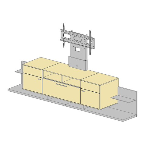
GWINNER ATENA Configuration guide

GWINNER

GWINNER ATENA Configuration guide

GWINNER MEDIA CONCEPT User manual

GWINNER

GWINNER MEDIA CONCEPT User manual

GWINNER CALEA CE1003 User manual

GWINNER

GWINNER CALEA CE1003 User manual

GWINNER TREVISO User manual

GWINNER

GWINNER TREVISO User manual

GWINNER MEDIA CONCEPT SP67 User manual

GWINNER

GWINNER MEDIA CONCEPT SP67 User manual

GWINNER MISANO R5516 User manual

GWINNER

GWINNER MISANO R5516 User manual

GWINNER FELINO Instruction Manual

GWINNER

GWINNER FELINO Instruction Manual

GWINNER CALEA User manual

GWINNER

GWINNER CALEA User manual

GWINNER MISANO User manual

GWINNER

GWINNER MISANO User manual
Popular Indoor Furnishing manuals by other brands

Heart of House Wiltshire 2388287 Assembly instructions

Heart of House

Heart of House Wiltshire 2388287 Assembly instructions

Rockler Blum GRP2283 1 instructions

Rockler

Rockler Blum GRP2283 1 instructions

ICW MD ARM Installation instruction

ICW

ICW MD ARM Installation instruction

Emmezeta LUNA SHELF Assembling Instruction

Emmezeta

Emmezeta LUNA SHELF Assembling Instruction

ofichairs Slim quick start guide

ofichairs

ofichairs Slim quick start guide

GUIDO MARIA KRETSCHMER HOME&LIVING Como 476344 manual

GUIDO MARIA KRETSCHMER HOME&LIVING

GUIDO MARIA KRETSCHMER HOME&LIVING Como 476344 manual

HAIOOU HO-SR001 Assembly instruction

HAIOOU

HAIOOU HO-SR001 Assembly instruction

Bonaldo Moglie e Marito Double Bed Assembly instructions

Bonaldo

Bonaldo Moglie e Marito Double Bed Assembly instructions

Dauphin Syncro-Automatic @Just magic2 Series owner's manual

Dauphin

Dauphin Syncro-Automatic @Just magic2 Series owner's manual

Songmics VASAGLE LET54 manual

Songmics

Songmics VASAGLE LET54 manual

Home Decorators Collection DP18019-P Use and care guide

Home Decorators Collection

Home Decorators Collection DP18019-P Use and care guide

RST Milo Motion OP-PECLB2M-MILO Assembly instructions

RST

RST Milo Motion OP-PECLB2M-MILO Assembly instructions

Bensons for Beds PENELOPE STK770625 Assembly instructions

Bensons for Beds

Bensons for Beds PENELOPE STK770625 Assembly instructions

Naomi Kids Low Loft Bed - 3 Drawer Chest Assembly instructions

Naomi Kids

Naomi Kids Low Loft Bed - 3 Drawer Chest Assembly instructions

Argos New Penton 245/7864 Assembly instructions

Argos

Argos New Penton 245/7864 Assembly instructions

Seconique Panama Console Table Assembly instructions

Seconique

Seconique Panama Console Table Assembly instructions

Costway HY10189 manual

Costway

Costway HY10189 manual

Office Star Products SPACE 63-58612 operating instructions

Office Star Products

Office Star Products SPACE 63-58612 operating instructions

manuals.online logo
manuals.online logoBrands
  • About & Mission
  • Contact us
  • Privacy Policy
  • Terms and Conditions

Copyright 2025 Manuals.Online. All Rights Reserved.