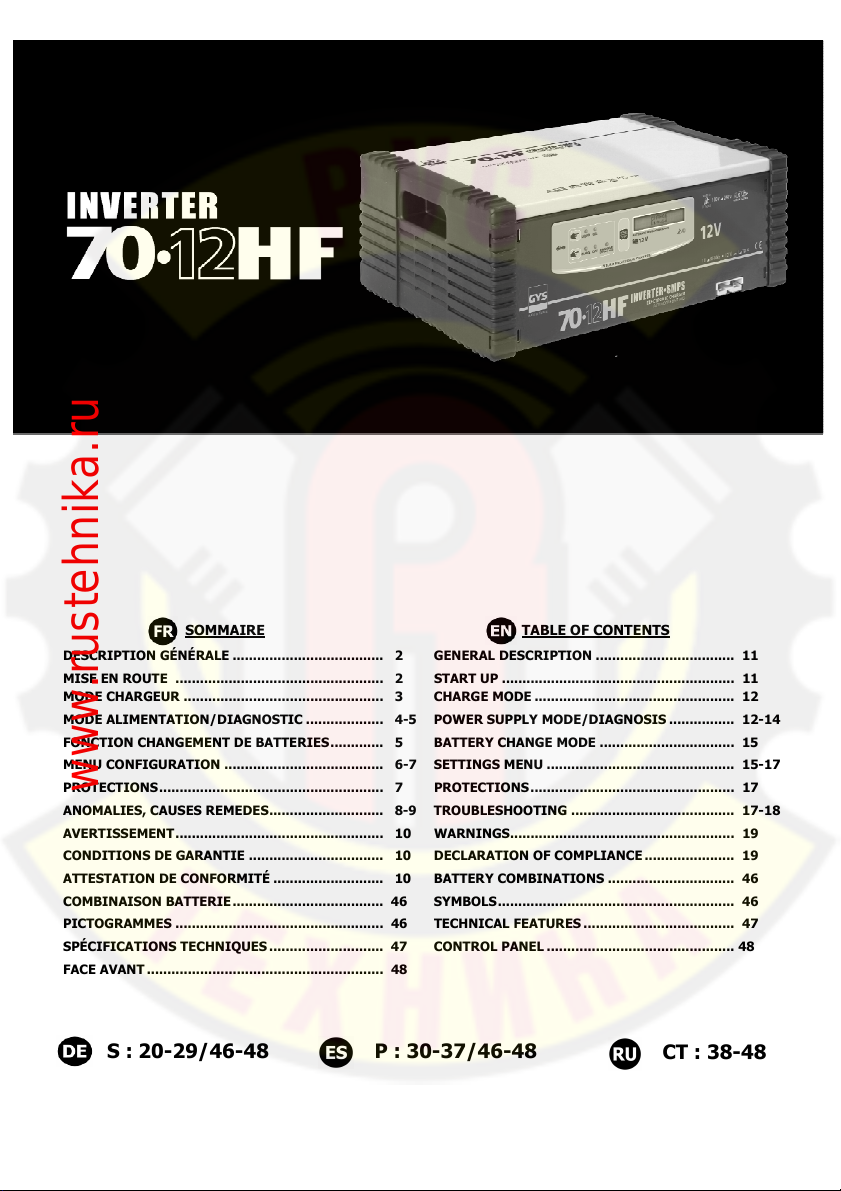
GYS Inverter 70-12HF Maintenance and service guide

73527_200611_V2
SOMMAIRE
TABLE OF CONTENTS
DESCRIPTION GÉNÉRALE ..................................... 2 GENERAL DESCRIPTION .................................. 11
MISE EN ROUTE ................................................... 2 START UP ......................................................... 11
MODE CHARGEUR ................................................. 3 CHARGE MODE ................................................. 12
MODE ALIMENTATION/DIAGNOSTIC ................... 4-5
POWER SUPPLY MODE/DIAGNOSIS ................ 12-14
FONCTION CHANGEMENT DE BATTERIES............. 5 BATTERY CHANGE MODE ................................. 15
MENU CONFIGURATION ....................................... 6-
SETTINGS MENU .............................................. 15-1
PROTECTIONS....................................................... PROTECTIONS.................................................. 1
ANOMALIES, CAUSES REMEDES............................ 8-9
TROUBLESHOOTING ........................................ 1 -18
AVERTISSEMENT................................................... 10 WARNINGS....................................................... 19
CONDITIONS DE GARANTIE ................................. 10 DECLARATION OF COMPLIANCE ...................... 19
ATTESTATION DE CONFORMITÉ ........................... 10 BATTERY COMBINATIONS ............................... 46
COMBINAISON BATTERIE..................................... 46 SYMBOLS.......................................................... 46
PICTOGRAMMES ................................................... 46 TECHNICAL FEATURES ..................................... 4
SPÉCIFICATIONS TECHNIQUES ............................ 4 CONTROL PANEL .............................................. 48
FACE AVANT .......................................................... 48
S
: 20
-
2
9
/46
-
48
P
:
30
-
3
/46
-
48
CT
:
38
-
48
www.rustehnika.ru

2
Inverter 70
12 HF
Ce manuel d'utilisation comprend des indications sur le fonctionnement de votre appareil et les
précautions à suivre pour votre sécurité. Merci de le lire attentivement avant première utilisation et
de le conserver soigneusement pour toute relecture future.
DESCRIPTION GENERALE
Inverter 70-12 F est une alimentation stabilisée de forte puissance basée sur la technologie SMPS
(Switch Mode Power Supply).
Conçu pour soutenir les batteries 12V (liquide ou gel) des véhicules en phase de diagnostic, il garantit
aussi une qualité de charge idéale pour l’entretien des modèles les plus évolués.
Ce chargeur peut recevoir des câbles de sortie jusqu’à 2x5m en 16mm² ou 2x12m en 50mm². Le
changement des câbles batterie nécessite un réétalonnage (cf. page 6).
Inverter 70-12 F dispose de 3 modes :
- Mode Chargeur : pour recharger les batteries de démarrage à électrolyte liquide ou gel (plomb,
plomb Calcium, plomb Calcium-Argent, AGM…) de 10 Ah à 850 Ah en 12V (6 éléments de 2V).
- Mode alimentation « Diagnostic » véhicules à l’arrêt : INVERTER 70 F subvient aux
besoins d’énergie jusqu’à 70A pour assurer à la batterie la compensation de courant utilisé pour
tester les gros consommateurs (ventilation moteur, lève-vitre, suspension électriques, etc.). La
fonction Diag+ permet de définir la tension à délivrer durant cette phase.
-Mode changement de batterie : pour alimenter le véhicule et éviter que l’électronique du
véhicule se réinitialise lors du changement de batterie.
MISE EN ROUTE
1. Brancher le chargeur sur la prise secteur.
Tension secteur auto adaptable tous pays de 100 V à 240V (50/60hz)
2. Positionner l’interrupteur sur « ON ».
Affichage pendant 3s « GYS Vx.x ».
3. Choisir ensuite le mode souhaité.
Si aucun mode n’est choisi, le chargeur se positionnera par défaut sur la
dernière configuration utilisée (sauf Diag +).
Auto diagnostic des câbles (si usure ou modification des dimensions)
Après 360 cycles de charge, Inverter 70 F propose à l’utilisateur de vérifier les câbles et de les
étalonner si besoin : « contrôle câbles ». Ce message apparaît pendant 10 secondes et tous les 30
démarrages tant que l’utilisateur n’a pas lancé une opération de contrôle (touche start). Pour plus
d’informations sur ce mode, se référer au sous menu « contrôle des câbles » page 6.
www.rustehnika.ru

3
Inverter 70
12 HF
MODE CHARGEUR
Respecter l’ordre de mise en route.
Précaution : Vérifier le niveau de l’électrolyte pour les batteries ouvertes. Compléter les niveaux si
nécessaire avant la charge.
1. Sélectionner le mode « C ARGE »
2. Sélectionner le type de batterie (liquide ou gel) :
Liquide : Plomb, plomb calcium, plomb calcium argent…
AGM/GEL : batteries Gel, sans entretien, AGM,…
3. Brancher les pinces : pince rouge sur le + de la batterie et pince noire sur le –
4. Appuyer sur « Start/Stop »
5. Avant de commencer la charge, Inverter 70 F analyse la batterie : tension/état
batterie… En cas d’anomalie Inverter 70 F vous l’indique (voir anomalies, causes,
remèdes, page 7).
6. Pendant la charge Inverter 70 F vous indique l’état d’avancement de la charge de
votre batterie (bargraph) ainsi que le courant (en Ampère) et la tension de charge
(Volts).
7. En fin de charge :
•Si l’option Floating est inactive (cf page 6), 70-12 F indique « Batterie chargée ».
•Si l’option Floating est active (cf page 6, l’inverter 70 F indique « Batterie
chargée » tout en continuant de maintenir en charge la batterie.
nb : Après la fin de charge, si la batterie reste branchée Inverter 70 F relance si
nécessaire, un cycle de charge pour compenser l’autodécharge de la batterie.
8. Appuyer sur « Start/Stop »
9. Positionner l’interrupteur sur « OFF ».
10. Débrancher le câble d’alimentation, puis les pinces de la batterie
www.rustehnika.ru

4
Inverter 70
12 HF
MODE ALIMENTATION/DIAGNOSTIC
Véhicules à l’arrêt, l’Inverter 70-12 F compense le courant utilisé (jusqu’à 70A) pour tester les gros
consommateurs : ventilation moteur, lève-vitre, suspension électriques etc…en délivrant une tension
stabilisée :
- 13,5V (réglage usine)
- 12V à 15V (fonction Diag +).
Fonction Diag +
La fonction « Diag + » vous permet de configurer, selon les préconisations du constructeur
automobile, la tension à délivrer durant la phase de diagnostic. Pour régler cette tension (par défaut
13,5V), se référer au menu de configuration page 5.
NB : Lors du passage à un autre mode d’utilisation, la fonction Diag + n’est pas gardée en
mémoire. Elle devra être réactivée à partir du mode diagnostic.
Branchement directement sur la batterie (mode recommandé)
Ce mode est recommandé car la détection d’erreur de polarité est fonctionnelle.
1. Sélectionner le mode « DIAGNOSTIC »
L’inverter 70-12 F indique : « DIAG U=13,5V »
2. DIAG + uniquement : Presser le bouton mode une seconde fois pendant 5 sec.
L’inverter 70-12 F indique la tension définie au préalable dans le menu de
configuration.
3. Appuyer sur « START »
4. Durant l’utilisation, le courant instantané consommé s’affiche.
5. Après utilisation, appuyer sur OFF
Débrancher le câble d’alimentation, puis les pinces de la batterie.
Branchement sans batterie,
Ce mode est non recommandé car sans batterie la détection d’erreur de polarité est inefficace.
1. Sélectionner le mode « DIAGNOSTIC »
L’inverter 70-12 F indique : « DIAG U=13,5V »
2. DIAG + uniquement : Presser le bouton mode une seconde fois pendant 5 sec.
L’inverter 70-12 F indique la tension définie au préalable dans le menu de
configuration.
3. Brancher : pince rouge sur les cosses connectées normalement à la borne + de la
batterie et la pince noire sur les cosses - connectées normalement à la borne - de la
batterie.
4. Appuyer sur « START »
5. L’afficheur indique « Diagnostic vérifier la polarité », pendant 10 secondes.
Inverter 70 F met en garde l’utilisateur sur le fait de bien vérifier la polarité.
www.rustehnika.ru

5
Inverter 70
12 HF
En effet, une erreur de polarité peut être dommageable pour l’électronique
embarquée.
6. Après vérification des polarités, appuyer sur Start pour lancer le mode.
Si l’utilisateur n’appuie pas sur « Start » sous 10 secondes, Inverter 70 F retourne à
l’étape 1.
7. Durant l’utilisation, le courant instantané consommé s’affiche :
« Diagnostic I=
XXX
A »
8. Pour mettre fin au mode diagnostic, Appuyer sur « Start/Stop »
9. Après utilisation, appuyer sur OFF
10. Débrancher le câble d’alimentation, puis les pinces de la batterie.
MODE CHANGEMENT DE BATTERIES
Inverter 70 F assure l’alimentation stabilisée des besoins électriques pendant le changement de la
batterie pour sauvegarder les mémoires.
1. Sélectionner le mode « C ANGE BAT »
2. Connecter :
a. la pince noire sur le châssis du véhicule.
b. La pince plus sur l’extrémité de la cosse connectée au + de la batterie, de telle
sorte que le remplacement de la batterie soit possible sans que la pince ne se
détache.
3. Appuyer sur « START », pour lancer le mode
4. Durant l’utilisation, le courant instantané consommé s’affiche.
5. Remplacer votre batterie, en respectant les polarités
ATTENTION : lors de la manipulation, attention à ne pas déconnecter les pinces
du chargeur sous risque de perdre les mémoires de l’électronique.
6. Après remplacement, appuyer sur « Start/Stop »
7. Débrancher le câble d’alimentation, puis les pinces de la batterie
www.rustehnika.ru

6
Inverter 70
12 HF
MENU CONFIGURATION
1. Pour accéder au menu Configuration :
Appuyer 5 secondes sur « START ».
2. Navigation :
Bouton mode : pour passer au sous menu suivant et valider les valeurs du
sous menu. Les sous menus défilent dans l’ordre suivant :
Langue Diag+ Démarrage retardé Contrôle des câbles Floating
Redémarrage automatique
Bouton batterie : pour sélectionner ou modifier les valeurs des sous menus
Nb. pour sous-menu démarrage retardé : Pour modifier plus rapidement les valeurs,
réaliser un appui prolongé.
Appuyer sur Start pour valider et sortir du menu « configuration », sauf
menu « contrôle câbles » qui lance la fonction.
Sous-menu :
Langues :
Pour changer la langue de l’afficheur.
Diag + :
Permet de définir la tension délivrée en mode "Diag +" jusqu'à 15,0V (la valeur par défaut est
13,5V). Un appui court sur le bouton batterie permet d’augmenter la valeur de 0,1V et un appui
prolongé l’augmente de 0,5V. A 15V, un appui supplémentaire fait passer à 12V. Appuyer sur
« START » pour valider et sortir du menu. Pour lancer le mode DIAG +, suivre toutes les étapes du
Mode Diagnostic p. 4.
Démarrages retardés :
valeur maximale : 24 heures (régler sur 00H pour désactiver la fonction).
Après avoir défini la minuterie, appuyer sur Start pour démarrer la « charge retardée ».
Suivre les instructions du mode « charge ».
Le rétro-éclairage de l’afficheur est désactivé et les leds sont éteintes jusqu’au début du cycle de
charge. En cas de batteries non connectées, le décompte continue sans qu’il soit affiché. A la fin
du décompte, aucun courant n’est délivré tant que l’utilisateur n’a pas branché sa batterie
correctement. En cas d’inversion de polarité, Inverter 70 F arrête le décompte puis redémarre
le décompte initial après correction par l’utilisateur.
www.rustehnika.ru

7
Inverter 70
12 HF
Contrôle des câbles :
Ce mode doit être utilisé lors de toutes modifications de câbles de sortie. Le 70-12 F peut recevoir
des câbles jusqu’à 2x5m en 16mm² ou 2x12m en 50mm².
1. Pour lancer le contrôle des câbles appuyer sur Start.
2. Le message « mettre les pinces en court-circuit » apparaît.
3. Mettre les pinces en court circuit pendant plus de 10 secondes.
Lorsque les pinces sont en court-circuit, le message précédent disparaît.
4. Le résultat s’affiche pendant 10 sec :
a. « Ok »: câbles en parfait état de fonctionnement.
Après 10 sec. Inverter 70-12 F revient ensuite automatiquement au menu principal.
b. « Vérifier câble / Start : étalonnage »: Inverter 70-12 F propose soit de vérifier les câbles soit
de les étalonner. Après 10 secondes, il revient au menu principal, si l’utilisateur ne lance pas
l’opération d’étalonnage (start).
c.
« Vérifier les câbles » : Pour cela, après avoir éteint le poste, nettoyer les contacts puis
vérifier l’état des câbles de charge. Les changer si nécessaire. Après cette opération, relancer
un cycle de « contrôle des câbles ».
Start « étalonnage » : l’étalonnage permet de calibrer le chargeur en fonction des câbles qui
lui sont connectés (longueur et section) afin d’avoir toujours le même courant de charge en
bout de pince. Pour cela garder les pinces en court-circuit, appuyer sur OK, Inverter 70-12 F
indique « étalonnage OK » puis revient au menu principal.
Floating
Après avoir chargé la batterie, La fonction floating reprend la charge pour compenser
l’autodécharge. Cette fonction permet de garder la batterie chargée à 100%.
D’origine cette fonction est active => afficheur « Configuration - fin de charge : float ».
Pour désactiver cette fonction, sélectionner « Configuration – fin de charge : arrêt ».
Redémarrage automatique :
Le redémarrage automatique ne fonctionne qu’en mode charge. Cette fonctionnalité permet, en cas
de coupure de courant, le redémarrage automatique du chargeur ainsi que la reprise de charge.
D’origine, cette fonction est active=> Afficheur « Configuration - Redémarrage : ON ».
Pour désactiver cette fonction, sélectionner : « Configuration : Redémarrage : OFF »
PROTECTIONS
Inverter 70 F est protégé contre les courts-circuits, inversions de polarité. Il dispose d’un système
anti-étincelle qui évite toutes étincelles lors du branchement du chargeur sur la batterie. Sans tension
aux pinces, l’inverter 70 F ne délivre pas de courant par sécurité. Le chargeur est protégé par 3
fusibles internes 40A (ref. 054554), ou un fusible 80A (ref. 051369) selon les versions, contre les
erreurs de manipulation : « Défaut Fusibles ».
www.rustehnika.ru

8
Inverter 70
12 HF
ANOMALIES, CAUSES, REMEDES
ANOMALIES CAUSES REMEDES
L’écran n’est plus éclairé et
affiche un décompte
heures/minutes
Fonctionnement normal en
charge retardée, si vous
souhaitez la désactiver, régler
cette dernière sur 00h dans le
menu de configuration (cf. p 5)
L’appareil émet un signal
sonore,
+ La led warning est allumée
+ l’afficheur indique :
« C ARGE EN COURS »
« Inversion de polarité »
Inverter 70 F a détecté une
inversion de polarité des
pinces.
Brancher la pince rouge au (+)
et la pince noire au (-)
l’afficheur indique :
« C ARGE EN COURS »
« Connecter le chargeur »
Le chargeur ne détecte pas de
batterie connectée
Vérifier que les pinces sont bien
connectées à la batterie
l’afficheur indique :
« CONSOMMATION
EXCESSIVE »
+ La led warning est allumée
Un consommateur est resté
connecté involontairement sur
la batterie pendant la charge.
(ex : phares)
Vérifier qu’il n’y a pas de
consommateur (ex : phase,
lumières intérieures, etc.)
Utiliser de préférence le chargeur
batterie déconnectée.
l’afficheur indique :
« ERREUR BATTERIE »
+ La led warning est allumée
La batterie connectée est une
24V. Chargeur non adapté.
Votre batterie est en court-
circuit ou endommagée. Batterie à remplacer.
l’afficheur indique :
« BATTERIE S »
+ La led warning est allumée Batterie 6V connectée Chargeur non adapté.
L’appareil indique :
« Défaut Fusibles » Mauvaise manipulation
Changer les fusibles internes par
une personne qualifiée
(ref 054651 : 80A)
L’appareil n’affiche rien
+ la led warning est allumée Réseau électrique défectueux
Vérifier que la tension du réseau
électrique est comprise entre 100
et 240V
Entrées et sorties d’air
obstruées
Veiller à dégager ou nettoyer les
sorties/entrées d’air
MODE CHARGEUR
L’afficheur indique :
« température trop élevée » Ventilateur défectueux Contacter votre revendeur
L’appareil émet un signal sonore
+led warning allumée
+ l’afficheur indique :
« DIAGNOSTIC »
« Inversion polarité »
Inverter 70 F a détecté une
inversion de polarité des
pinces.
Brancher la pince rouge au (+)
et la pince noire au (-).
1- Diagnostic avec batterie :
Vérifier que les pinces sont bien
connectées à la batterie.
MODE DIAGNOSTIC
l’afficheur indique :
« DIAGNOSTIC »
« Connecter le chargeur »
Le chargeur ne détecte pas de
batterie connectée. 2- Diagnostic sans batterie :
Fonctionnement normal, appuyer
sur Start pour lancer le mode.
www.rustehnika.ru

9
Inverter 70
12 HF
ANOMALIES CAUSES REMEDES
L’appareil émet un signal sonore,
+ La led warning est allumée
+ l’afficheur indique :
« DIAGNOSTIC »
« Vérifier la polarité »
Fonctionnement normal en mode
diagnostic sans batterie :
Pour une question de sécurité
Inverter 70 F demande à
l’utilisateur de vérifier le
raccordement des pinces (polarité)
avant de lancer le mode.
L’afficheur indique :
« CONSOMMATION >70A »
+ Signale sonore
Consommation excessive par
rapport à la puissance du
chargeur
Arrêter certains
consommateurs pour arriver à une
situation normale.
l’afficheur indique :
« DIAGNOSTIC »
« Pinces en court-circuit »
Pinces en court circuit Vérifier le branchement des pinces
de charge.
L’appareil indique :
« Défaut Fusibles » Mauvaise manipulation
Changer les fusibles internes par
une personne qualifiée
(ref 054651 : 80A)
L’appareil n’affiche rien
+ la led warning est allumée Réseau électrique défectueux
Vérifier que la tension du réseau
électrique est comprise entre 100
et 240V
Entrées et sorties d’air obstruées Veiller à dégager ou nettoyer les
sorties/entrées d’air
MODE DIAGNOSTIC
L’afficheur indique :
« température trop élevée » Ventilateur défectueux Contacter un revendeur
L’appareil émet un signal sonore,
+ La led warning est allumée.
+ l’afficheur indique :
« C ANGE BAT »
« Inversion polarité »
Inverter 70 F a détecté une
inversion de polarité des pinces.
Brancher la pince rouge au (+) et
la pince noire au (-).
l’afficheur indique :
« C ANGE BAT »
« Connecter le chargeur »
Le chargeur ne détecte pas de
batterie connectée
Vérifier que les pinces sont bien
connectées à la batterie
L’afficheur indique :
« CONSOMMATION >70A »
+ Signale sonore
Consommation excessive par
rapport à la puissance du
chargeur
Arrêter certains
consommateurs pour arriver à une
situation normale.
l’afficheur indique :
« C ANGE BAT »
« Pinces en court-circuit »
Pinces en court circuit Vérifier le branchement des pinces
de charge.
L’appareil indique :
« Défaut Fusibles » Mauvaise manipulation
Changer les fusibles internes par
une personne qualifiée
(ref 054651 : 80A)
L’appareil n’affiche rien
+ la led warning allumée Réseau électrique défectueux
Vérifier que la tension du réseau
électrique est comprise entre 100
et 240V
Entrées et sorties d’air obstruées Veiller à dégager ou nettoyer les
sorties/entrées d’air
MODE CHANGEMENT BATTERIES
L’afficheur indique :
« température trop élevée ». Ventilateur défectueux Contacter un revendeur
www.rustehnika.ru

10
Inverter 70
12 HF
AVERTISSEMENTS
▪ Gaz explosif, éviter les flammes et les étincelles. Pendant la charge, la batterie doit être placée dans
un emplacement bien aéré.
▪ Protéger contre la pluie et l’humidité.
▪ Votre chargeur doit être raccordé à un socle de prise de courant relié à la terre.
▪ Si le câble d’alimentation est endommagé, ou si le fusible interne est fondu (ref 054651)), il doit être
remplacé par le fabricant, son service après vente ou une personne de qualification similaire, afin
d’éviter un danger.
▪ A n'utiliser en aucun cas pour charger des piles ou des batteries non-rechargeables.
▪ La borne de la batterie non reliée au châssis doit être connectée la première. L’autre connexion doit
être effectuée sur le châssis loin de la batterie et de la canalisation de combustible.
▪ Après l’opération de charge, débrancher le chargeur du réseau, puis retirer la connexion du châssis
et la connexion de la batterie, dans l’ordre indiqué.
▪ L’appareil doit être placé de façon telle que la fiche de prise de courant soit accessible.
▪ L’appareil ne doit pas être utilisé comme un jouet par de jeunes enfants, ou être utilisé par de
jeunes enfants ou personnes handicapés sans surveillance.
▪ Produit faisant l’objet d’une collecte sélective. Ne pas jeter dans une poubelle domestique.
▪ Ne pas mettre en court circuit les pinces pendant la charge.
CONDITIONS DE GARANTIE
•La garantie couvre tout défaut ou vice de fabrication pendant 1 an, à compter de la date
d’achat (pièces et main d’œuvre).
•La garantie ne couvre pas les erreurs de tension, incidents dus à un mauvais usage, chute,
démontage ou toute autre avarie due au transport.
•La garantie ne couvre pas l’usure normale des pièces (Ex. : câbles, pinces, etc.).
En cas de panne, retournez l’appareil au point S.A.V GYS, en y joignant :
-Un justificatif d’achat daté (ticket de sortie de caisse, facture….)
-une note explicative de la panne.
Attention : notre SAV n’accepte pas les retours en port dû.
Après la garantie, notre SAV assure les réparations après acceptation d’un devis.
Contact SAV : Société Gys-134 Bd des Loges
BP 4159-53941 Saint-Berthevin Cedex
Fax: +33 (0)2 43 01 23 75
ATTESTATION DE CONFORMITE
La société GYS atteste que le chargeur décrit dans ce manuel :
Inverter 0 HF
Est fabriqué conformément aux exigences des directives européennes suivantes :
- Directive Basse Tension : 2006/95/CE du 12/12/06.
- Directive CEM : 2004/108/CE du 15/12/2004- 03/05/1989.
ils sont pour cela conformes aux normes harmonisées :
- EN 60335-2-29 & EN 55014-1 / EN 55014-2
Date de marquage CE : mai 2009.
01/05/09 Nicolas BOUYGUES
Société GYS Président Directeur Général/ CEO
134 BD des Loges
53941 Saint Berthevin
www.rustehnika.ru

11
Inverter 70
12 HF
This manual contains safety and operating instructions.
Read it carefully before using the charger
for the first time and keep it in a safe place for any future reference.
GENERAL DESCRIPTION
The Inverter 70 F is a high powered stabilised power supply incorporating SMPS (Switch Mode Power
Supply) technology.
Designed to sustain 12V batteries (liquid or gel) for vehicles during diagnostic work, and will ensure
an ideal charging cycle for battery maintenance for the most modern vehicles
Inverter 70 F has 3 modes :
- « Charge Mode »: to charge liquid or gel electrolyte (lead, lead Calcium, lead Calcium-Silver,
AGM) starter batteries from 10Ah to 850Ah in 12V (6 elements of 2V).
- « Diagnostic Mode »: on a stationary vehicle, the INVERTER 70 F supplies up to 70A to
ensure compensation of the current used by high-energy consumers (engine fan, window
regulator, electronic suspension, etc) during testing. This reduces the risk of damage or data
loss due to deep battery discharge.
-« Change Battery » Mode: ensures a stabilised power supply to the vehicle during battery
replacement to preserve memory settings.
START UP
1. Connect the charger to the mains.
Mains voltage automatically adaptable for all countries from 100V to
240V (50/60hz)
2. Switch « ON ».
After 3 seconds the display will show « GYS Vx.x ».
3. Select the required mode.
If no modes are selected, the charger will default to the last setting
used.
Automatic diagnosis of the cables (if worn out or dimensions modified)
After 360 charge cycles, the Inverter 70 F offers the user to check and calibrate the cables if
needed: « check cables ». This message is displayed for 10 seconds and every 30 starts until the user
launches the checking operation (start button). For more information on this mode, please refer to the
sub menu « check cables » page 14.
www.rustehnika.ru

12
Inverter 70
12 HF
CHARGE MODE
Ensure that the correct sequence is followed:
Precaution: Check the electrolyte level and fill if necessary before charging.
1. Select « C ARGE » mode
2. Select type of battery (LIQUID or AGM/GEL):
3. Connect the clamps: red clamp on the "+" battery terminal, and black clamp on the
"-" battery terminal
4. Press « Start/Stop »
5. Before beginning the charge the Inverter 70-12 F will analyse the battery
voltage/condition and will indicate its status (see the TROUBLES OOTING section).
6. During the charge, the Inverter 70-12 F indicates the charge status of the battery
(bar graph) as well as the current (Ah) and charge voltage (Volts).
7. At the end of the charge :
• If the « Floating » option is not activated (see page 14), the Inverter 70 F
indicates « Battery charged ».
•If the « Floating » option is activated (see page 14, the Inverter 70 F will display
« Battery charged »
NB : When the charge ends, if the battery remains connected, the Inverter 70 F
starts again, providing, if necessary, a charge cycle to compensate the automatic
discharge of the battery.
8. Press « Start/Stop »
9. Switch « OFF ».
10. Unplug the power supply cable first, then the battery clamps.
POWER SUPPLY MODE/DIAGNOSIS
On a stationary vehicle, the INVERTER 70 F supplies up to 70A to ensure compensation of the
current used by high-energy consumers (engine fan, window regulator, electronic suspension etc…)
during testing
- 13.5V - Default setting
- 12 - 15V - Diag+ function (see Page …. for full instructions for this feature)
www.rustehnika.ru

13
Inverter 70
12 HF
DIAGNOSTIC FUNCTION
Battery connection PRIOR to mode Selection (recommended)
Polarity reversal detection is activated.
1. Select « DIAGNOSTIC MODE »
INVERTER 70.12hf displays « DIAG V = 13.5v »
2. Press « START/STOP »
3. During the diagnostic, the instantaneous current consumption is displayed.
4. When the diagnostic has finished, turn the machine off
5. Unplug the power supply cable, then disconnect the clamps.
Mode Selection PRIOR to battery connection
Not recommended as this will not activate the polarity reversal detection.
1. Select the « DIAGNOSTIC MODE »
INVERTER 70.12hf displays « DIAG V = 13.5v »
2. Connect the clamps: Red clamp on the "+" battery terminal, and the black clamp
on the "-" terminal
3. Press « START/STOP »
4. The message « Diagnosis check the polarity » is displayed for 10 seconds.
Check the polarity of the clamps - a polarity reversal can damage the on-board
electronics
5. Press « START/STOP »
If the « Start » button is not pressed within 10 seconds, the Inverter 70 F will
revert back to Step 1.
6. During the diagnostic, the instantaneous current consumption is displayed:
« Diagnosis I=
XXX
A »
7. To end the diagnosis press « Start/Stop »
8. After use, turn the machine OFF
9. Unplug the power cable and then disconnect the clamps.
www.rustehnika.ru

14
Inverter 70
12 HF
DIAG+ FUNCTION
The Diag+ function allows the user to specify the voltage delivered to the battery where a value other
than 13.5V is required (according to the manufacturers specifications.) To use this function, follow the
instructions on page 15 to set up the required voltage.
Nb: When the user exits Diag+ mode, the selected voltage setting will not be saved and
will revert back to 13.5V (default).
Setting the required stabilised voltage (between 12-15V)
•Press and hold the button for 5 seconds to enter "Setting" menu
•In settings menu use the Mode Selection button to scroll to DIAG+
•The screen will display DIAG+ U = 13.5V (or last used voltage setting)
•Use the Battery Type selection button to scroll until the Inverter displays the
required volate eg: DIAG+ U = 14.3V
•Press the « START/STOP » button to confirm selection.
Using DIAG+ function
Enter DIAG+ Mode
•Connect the clamps to the battery
Red clamp to "+" terminal, Black clamp to "-" terminal
•Press Mode Selection button until the LED reaches DIAG mode.
•Press and hold the Mode Selection button for 5 seconds
Inverter will display "DIAG+ U = 13.5V" (or the voltage
selected in section 1)
•Press Start/Stop button
During the diagnosis, the Inverter 70.12 will display the instantaneous current consumption.
•To end the process, switch "OFF"
•Disconnect the clamps
Warning - if DIAG+ mode is selected before the clamps are connected to the battery, the Polarity
Reversal detection will not operate
www.rustehnika.ru

15
Inverter 70
12 HF
BATTERY CHANGE MODE
The Inverter 70 F ensures a stabilised power supply while changing the battery in order to save the
memory settings.
1. Select « C ANGE BAT » mode
2. Connect:
c. The black "-" clamp to the vehicle chassis.
d. The "+" clamp to the end of the lug connected to the "+" battery terminal, in
such a way that the battery can be changed without disconnecting the clamp.
3. Press « START/STOP », to launch the mode
4. During the process the instantaneous current consumption is displayed.
5. Change the battery ensuring the polarity is correct
CAUTION: while exchanging the batteries, be careful not to disconnect the
charger clamps as it can cause the loss of electronic data
6. After changing, press « Start/Stop »
7. Unplug the power cable.
8. Unplug the clamps /or the connector from the battery. .
SETTING MENU
1. To access the Setting Menu press
Press and hold « START » for 5 seconds.
2. Navigation :
Mode button: will access the next sub menu and confirm the sub menu
settings. The sub menus are displayed in the following order:
Language Diag + Timer Cables Testing Charge End Restart
Battery Selection button: will select or modify the values of the sub menus.
NB. For the sub menu 'Timer': To modify the settings quickly, press and hold.
Press Start/Stop to confirm and exit the « setting » menu,
In « Cables Testing » press Start/Stop to commence testing.
Sub menu :
Language :
Changes the language of the display.
Diag +
This function allows the user to set up the voltage to be delivered whilst using the Diag + function
up to 15.0V (nb: the default voltage setting is 13.5V)
Press the battery selection button quickly to increase the value of the voltage by 0.1V.
Press and hold the battery selection button to increase the value of the voltage by 0.5V
When you have reached the maximum 15V it will revert back to 12V.
Press Start to accept the required setting and exit the menu. To start using DIAG+ mode, follow
the steps of the Diagnostic mode listed on page. 13.
www.rustehnika.ru

16
Inverter 70
12 HF
Timer:
Maximum value : 24 hours (displays eg : 24 )
Minimum value : 00 = no delay set
To set the timer, enter Setting menu, and when 'Timer' is displayed press the Mode Select
button. Use the Battery Type button to scroll through from 00-24 (after 24 the display
will revert to 00 ) - Press the Start/Stop button quickly to ok the setting.
Follow the instructions for the « charge » mode.
The display backlight will deactivate and the LEDs will turn off until the beginning of the charge
cycle. The display will show a count-down to the start of the charge
If a battery is not connected, the count-down will continue without being displayed. At the end of
the count the inverter will display "Connect Battery", and no current will be supplied until a
battery is connected. In case of polarity reversal, the Inverter 70 F will terminate the count-
down, restarting when the battery is connected correctly.
Cables Testing:
This mode must be used each time the output cables are changed. To launch the cable check press
the Start/Stop button. The Inverter 70.12 is compatible with 2 x 5m 16mm
2
or 2 x 12m 50 mm
2
cables.
1. The message « Short circuit the clamps » is displayed.
2. Put the clamps in short circuit for more than 10 seconds.
When the clamps are in short circuit, the message, « put the clamp in short-circuit »
disappears.
3. The result is displayed for 10 sec :
d. « Ok »: cables are in good working condition.
After 10 sec. Inverter 70 F will automatically revert back to the main menu.
e. « Check cable / Start: calibrate »: The Inverter 70 F offers either to check or calibrate the
cables using the start/stop button. If the user does not launch the calibration operation
within 10 seconds the unit will revert back to the main menu.
« Check cables » : After switching off the charger, clean the contacts then check the
charge cables and change them if necessary. After this is done, restart the « check
cables » cycle.
Start « calibration »: this function enables the Inverter to calibrate the cables connected
to the machine (length and section) to ensure that the current delivered at the clamps is
correct. To calibrate, put the clamps in short-circuit, press Start/Stop, the Inverter 70 F
displays « calibration OK » then goes back to the main menu.
Charge End
After the battery has been charged, 'Floating' mode continues to deliver a current to the battery to
maintain a maximum charge.
This function is initially active. To disable this function go into the settings menu, select "Restart"
and use the battery type selection button to toggle Float/OFF
Restart
The automatic restart function only works in charge mode - it enables an automatic restart for the
charger in the event of unexpected power loss.
This function is initially active. To disable this function, go into the settings menu, select "Restart",
and use the battery type selection button to toggle ON/OFF
www.rustehnika.ru

17
Inverter 70
12 HF
PROTECTION
The Inverter is protected against short-circuits, polarity inversions and engine starts. It has an anti-
spark feature which prevents sparks whilst connecting the inverter to the battery. The inverter will not
deliver current if there is no battery detected (no voltage in the clamps). The charger is protected by
3 x 40A fuses (GYS Ref. 054554) or 1 x 80A (Ref: 051369) - check existing fuse.
TROUBLESHOOTING
PROBLEMS CAUSES SOLUTIONS
The display panel shows count-down ( :MM) The delay timer has been
activated
Normal display in Timer mode - to
deactivate the timer, follow 'Timer'
instructions in Setting menu - set
value to 00
The charger produces a warning sound,
+ the led warning is on
+ the display shows :
« C ARGE IN PROGRESS »
« Polarity reversal »
The Inverter 70 F detects a
polarity reversal in the
clamps
Connect the red clamp to the "+"
terminal, and the black clamp to the "-
" terminal
The display shows :
« C ARGE IN PROGRESS »
« Connect the charger »
The charger cannot detect a
battery
Ensure the battery terminals are
clean, and the clamps are securely
connected
The display shows :
« EXCESSIVE CONSUMPTION »
+ The LED warning is illuminated
A consumer has been left
on
(eg : eadlights)
Turn off any active consumers,
disconnect the clamps and re-connect
to re-start the charge
The display shows:
« BATTERY ERROR »
+ The LED warning is illuminated
The charger has detected a
24V battery
Charger not specified for 24V
Use a compatible charger
The battery is in short
circuit or damaged. Replace the Battery
The display shows:
« BATTERY Out of Order »
+ The LED warning is illuminated The charger has detected a
6V battery
Charger not speciified for 6V
Use a compatible charger
The display shows:
« Faulty fuses » The fuses have blown
Change the Internal fuses
(Qualified staff only)
(ref 054651 : 80A)
The charger displays nothing
+ the LED warning is illuminated Electrical network fault Check the voltage of the electrical
network is between 100 and 240V
Ventilation holes blocked Check and clear ventilation holes
CHARGER MODE
The display shows:
« temperature too high » Faulty fan Contact your retailer
The charger produces a warning sound,
+ The LED warning is illuminated
+ the display shows :
« DIAGNOSIS »
« Polarity reversal »
The Inverter 70 F detects a
polarity reversal in the
clamps
Connect the red clamp to the "+"
terminal, and the black clamp to the "-
" terminal
1- Whilst clamps are connected,
ensure the battery terminals are
clean, and the clamps are securely
connected.
DIAGNOSIS MODE
The display shows:
« DIAGNOSTIC »
« Connect the charger »
The charger cannot detect a
battery 2- If the clamps have not been
connected, this is a normal response
for the charger.
www.rustehnika.ru

18
Inverter 70
12 HF
PROBLEMS CAUSES SOLUTIONS
The charger produces a warning
sound
+ the LED warning is illuminated
+ the display shows :
« DIAGNOSIS »
« Check polarity »
Normal display in diagnosis mode if
clamps are not connected.
Manually check the polarity of the
clamps before connecting to the
battery
The display shows :
« CONSUMPTION >70A »
+ Warning sound
Electrical consumption greater than
the capacity of the charger
Switch off electrical consumers (i.e
eadlights) before re-trying.
The display shows :
« DIAGNOSIS »
« Clamps in short circuit »
Clamps in short circuit Check the connection of the charge
clamps.
The display shows :
« Faulty fuses » The fuses have blown.
Change the internal fuses (qualified
staff only)
(ref 054651 : 80A)
The charger does not display
anything
+ the LED warning is illuminated
+ Warning sounds twice
Electrical network fault Check the voltage of the electrical
network isbetween 100 and 240V
Ventilation holes blocked Check and clear ventilation holes
DIAGNOSIS MODE
The display shows:
« temperature too high » Faulty fan Contact your retailer
The charger produces an alert
sound,
+ the LED warning is illuminated
+ the display shows :
« C ANGE BAT »
« Polarity reversal »
The Inverter 70 F detects a
polarity reversal in the clamps
Connect the red clamp to the "+"
terminal, and the black clamp to the "-
" terminal
The display shows :
« C ANGE BAT »
« Connect the charger »
The charger cannot detect a
battery
Ensure the battery terminals are
clean, and the clamps are securely
connected
The display shows :
« CONSUMPTION >70A »
+ Sound alert
Electrical consumption greater than
the capacity of the charger
Switch off electrical consumers (i.e
eadlights) before re-trying.
The display shows:
« C ANGE BAT »
« Clamps in short circuit »
Clamps in short circuit Check the connection of the charge
clamps.
The charger shows:
« Faulty fuses » The fuses have blown.
Change the internal fuses (qualified
staff only)
(ref 054651 : 80A)
The charger does not display
anything
+ the LED warning is illuminated
+ Warning sounds twice
Electrical network fault Check the voltage of the electrical
network is between 100 and 240V
Ventilation holes blocked Check and clear ventilation holes
CHANGING BATTERIES MODE
The display shows:
« temperature too high » Faulty fan Contact your retailer
www.rustehnika.ru

19
Inverter 70
12 HF
WARNINGS
▪ Explosive gas, avoid flame and sparks. During the charge, the battery must be placed in a well
ventilated area.
▪ Protect against rain and moisture.
▪ The charger must be connected to an EART ED power supply.
▪ If the electricity supply cable is damaged, or if the internal fuse has blown (ref 054651), it must be
replaced by the manufacturer, its after sales service, or a person with the same qualifications to avoid
danger.
▪ Do not use to charge small batteries (i.e those with a capacity less than the minimum stated on the
Inverter), or non rechargeable batteries.
▪ Always ensure the Red clamp is connected to the "+" battery terminal first.
▪ If it is necessary to connect the black clamp to the vehicle chassis, make sure it is a safe distance
from the battery and the fuel/exhaust pipe.
▪ After charging, disconnect the charger from the outlet, then disconnect the clamp from the frame
and the battery in the indicated order.
▪ The charger must be placed so that the socket is always accessible.
▪ This charger is not a toy.
▪This product should be disposed of at an appropriate recycling facility - do not dispose of in domestic
waste.
▪ Do not short-circuit the clamps during use.
DECLARATION OF COMPLIANCE
The GYS Company testifies that the charger described in this manual:
Inverter 0 HF
Is manufactured in compliance with the requirements of the following European directives:
- Low Voltage Directive : 2006/95/CE du 12/12/06
- EMC Directive : 2004/108/CE du 15/12/2004- 03/05/1989.
It therefore complies with the following harmonized standards:
- EN 60335-2-29 & EN 55014-1 / EN 55014-2
Marking dates CE/GS : May 2009.
01/05/09 Nicolas BOUYGUES
Société GYS Président Directeur Général/ CEO
134 BD des Loges
53941 Saint Berthevin
www.rustehnika.ru

20
Inverter 70
12 HF
Wir freuen uns, dass Sie sich für ein Markengerät der Firma GYS entschieden haben und danken
Ihnen für das entgegengebrachte Vertrauen. Bitte lesen Sie sorgfältig vor dem Erstgebrauch diese
Betriebsanleitung.
BESCHREIBUNG
Inverter 70-12 F ist eine leistungssarke Gleichspannungsquelle mit SMPS Technologie (Switch Mode
Power Supply), konzipiert um die Leistung von 12V Batterien (Säure oder Gel) während der KfZ-
Diagnose aufrecht zu erhalten. Es sichert eine optimale Ladequalität für die Wartung von Batterien der
neuesten Technologie.
An diesem Batterieladegerät können Netzstromkabel bis 2x5m Ø16mm² oder 2x12m Ø50mm²
angeschlossen werden. Bei jeder Änderung der Kabel muss der Modus «Kabel überprüfen» angewählt
werden (s.S.22).
Inverter 70-12 F verfügt über 3 Modi:
- Lademodus: um Startbatterien mit Säure- oder Gel- Elektrolyt (Blei, Blei-Kalzium, Blei
Kalzium-Silber, AGM) von 10Ah bis 850Ah bei 12V (6 x 2V Elemente) aufzuladen.
- Diagnosemodus: zur Stromversorgung und Stützung der Bordbatterie während der Diagnose
bei Motorstillstand an sämtlichen elektronischen Verbrauchern bis 70A (Motorkühlung,
Fensterheber, Bordelektronik usw.). Die Funktion Diag+ ermöglicht die Einstellung der
Diagnosespannung.
-Batteriewechsel – Modus (Autosicherheitsspeicher): sichert während des Ausbaus
der Batterie eine stabile Netzspannung der elektrischen Verbraucher, um den Verlust von
Speicherinhalten zu vermeiden.
NETZANSCHLUSS – INBETRIEBNAHME
1. Schließen Sie das Batterieladegerät an die Netzspannung an
Die Netzspannung wird (je nach landespezifischer Netzspannung)
automatisch von 100V bis 240V (50/60 z) angepasst.
2. Schalten Sie auf «ON»
Für 3 sek erscheint auf dem Display «GYS Vx.x »
3. Stellen Sie nun den gewünschten Modus ein.
Werden die Modi nicht spezifisch ausgewählt, greift das Gerät auf die
zuletzt benutzen Einstellungen zurück (außer Diag+).
Automatische Zustandsdiagnose der Kabel (wenn diese abgenutzt sind oder sich die
Abmessungen verändert haben)
Nach 360 Ladegängen erscheint auf dem Display die Anzeige «Kabel überprüfen»:
Das Gerät fordert Sie auf das Startkabel zu überprüfen und gegebenenfalls auszutauschen.
Diese Meldung erscheint für 10 sek bei jedem 30. Start des Gerätes bis Sie manuell die Überprüfung
starten (Start-Schalter). Für weitere Informationen zu dieser Funktion, lesen Sie bitte das Unterkapitel
«Kabel überprüfen», S.22.
www.rustehnika.ru
Table of contents
Languages:
Other GYS Batteries Charger manuals

GYS
GYS 029200 User manual

GYS
GYS BATIUM 25/24 User manual

GYS
GYS BATIUM 25 User manual

GYS
GYS BATIUM 25/24 User manual

GYS
GYS NOMAD POWER 15 AIR User manual

GYS
GYS GYSFLASH 8.12 PL User manual

GYS
GYS STARTIUM 330E User manual

GYS
GYS GYSFLASH 3.48 PL User manual

GYS
GYS STARTPACK 12.24 User manual

GYS
GYS BATIUM 7/12 User manual

GYS
GYS STARTPACK TRUCK User manual

GYS
GYS GYSFLASH 100.12 HF User manual

GYS
GYS BATIUM 7/12 User manual

GYS
GYS NEOSTART 320 User manual

GYS
GYS GYSTECH 12/12 User manual

GYS
GYS STARTPACK TRUCK User manual

GYS
GYS ENERGY 124 User manual

GYS
GYS START 200 User manual

GYS
GYS GYSPack 610 User manual

GYS
GYS START 200 User manual