094275_f_gb_zstwin_s haacon hebetechnik gmbh Phone +49 (0) 9375 - 84-0 Fax +49 (0) 9375 - 84-66 1
GB
OPERATING INSTRUCTIONS
(Translation)
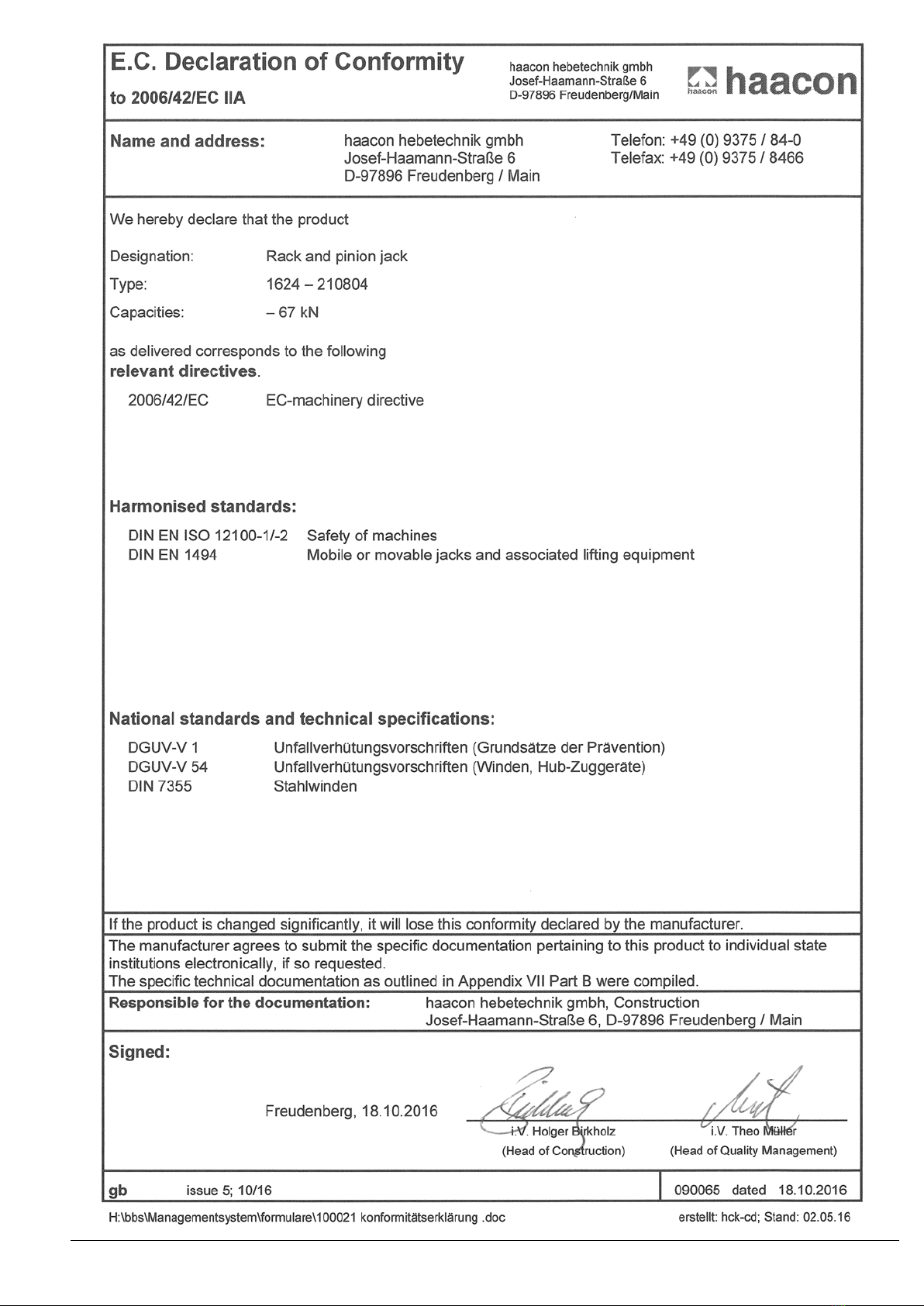
Rack and pinion jack
Type 1624.10 - 210804
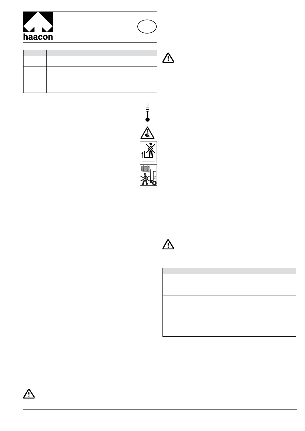
1. USER GROUPS
Duties Qualifications
Operator Operation,
visual inspection
Instruction by means of the operat-
ing instructions; authorised person 1
Specialist
personnel
Assembly,
disassembly, repair,
maintenance
Mechanic
Tests Authorised person 2 per TRBS-1203
(Technical expert)
2. SAFETY INSTRUCTIONS
Intended Use
Only use the rack and pinion jack according to the specifica-
tions contained in the operating instructions.
– Only use for lifting or lowering.
– Only use in a sound technical condition.
– Only to be operated by instructed personnel.
– Only use for the intended application (pulling / pushing).
Safety-conscious working
– First read the operating instructions.
– Always be conscious of safety and hazards when working.
– Observe lifting device and load during all movements.
– Immediately report any damage or defects to the person in charge.
– Repair equipment first before continuing work!
– Do not leave the load suspended without supervision.
– Transport device protected against impacts and shocks,
falling over or toppling.
The following is prohibited:
– Overload (--> technical data, type plate, payload plate)
– Exceeding the maximum lift.
– Impacts, blows.
Use exclusions
– Not suitable for permanent operation and vibration loads.
– Not approved for use as builders' hoist (DGUV-R 100-500-2.30).
– Not approved for use in explosive areas/environments.
– Not suitable for aggressive environments.
– Not suitable for dangerous loads
Organisational means
– Ensuring that these operating instructions are available at all times.
– Ensuring that only instructed personnel works with the rack and
pinion jack.
– Checking at regular intervals whether work is carried out in a safety-
and danger-conscious manner.
Maintenance and repair
Have maintenance and repair work carried out by skilled personnel only.
Only used original spare parts for repairs. Do not carry out any modifi-
cations or conversions on safety-relevant parts.
Additions must not jeopardise the safety of the winch.
Further instructions that must be observed
The rules and regulations valid in the respective country of application in
their respectively valid version have to be observed. In Germany, these
are currently:
– German Industrial Health and Safety Ordinance (BetrSichV)
– Accident Prevention Regulation DGUV-V 54
– DIN 7355 Steel Winches; DIN EN 1494
– EC Directive 2006/42/EC
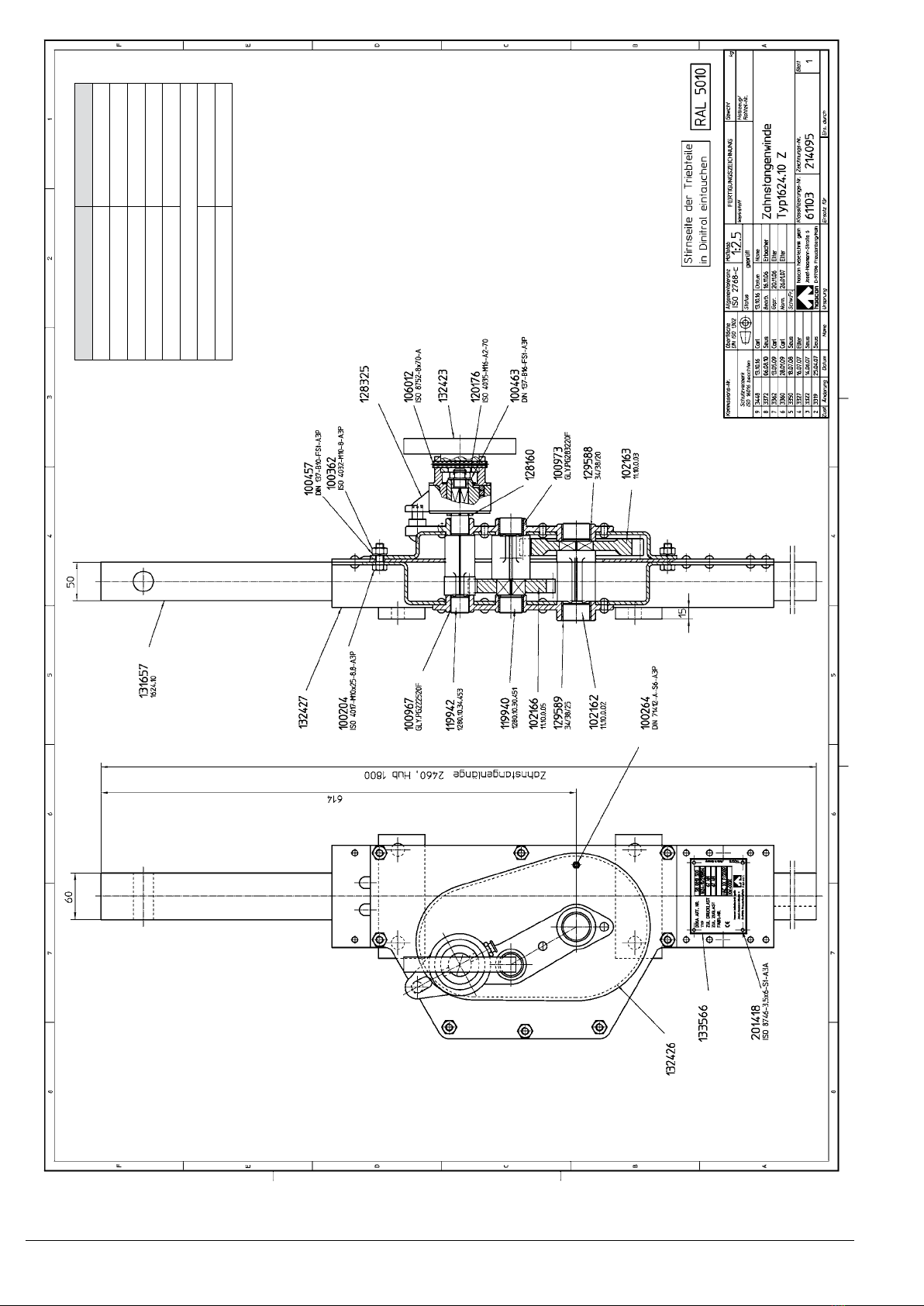
3. TECHNICAL SPECIFICATIONS see drawing.
4. SETUP
Modification of steel winch series type 11. Reliable spur gear made of
high-quality hardened or tempered steel . Equipped with a bilaterally
effective brake head. Complies with the accident prevention regulation
"Winches, lifting and pulling devices“ DGUV-V 54.
The brake head mounted on the winch reliably retains the load in any positi-
on. Clockwise turning raises the load, anticlockwise turning lowers the load.
Two lugs on the shaft and a drilled hole in the rack permit (the custo-
mer) to bolt it to the load to be lifted. The design on hand permits a
motor drive to be mounted onto the brake head.
CAUTION!
The operator is responsible for the safe assembly, the correct
selection of mounted parts, the secure seat of the drive motor
and observance of the permissible speed!
5. OPERATION
Use with motor
Before it is used, securely fasten the winch in the drilled holes intended
for that purpose. Push on the drive such that the winch drive shaft only
has to absorb the torque and no other forces. It must be ensured by
on-site means that the drive is reliably switched off before it reaches its
final position.
CAUTION!
Observe permissible input speed!
Prevent overload using suitable measures.
This applies along the lifting path and on reaching the end of lift.
No permanent operation! Keep the declared load cycle.
6. TESTING
The equipment must be checked in accordance with the conditions
of use and the operating conditions at least once per year by an
authorised person 2 per TRBS 1203 (Technical expert) (testing per
BetrSichV, §10, sect. 2 represents implementation of the EC guidelines
89/391/EEC and 95/63/EC or the annual occupational safety inspection
per DGUV-V 54, §23, sect. 2 and DGUV-G 309-007). These checks
must be documented:
– Before commissioning.
– After significant alterations before recommissioning.
– At least once per year.
– In the event of unusual occurrences arising that could have detrimen-
tal effects on the safety of the winch (extraordinary tests, e.g. after a
long period of inactivity, accidents, natural events).
– After repair works that could have an influence on the safety of the
winch.
Technical experts (AP2) are persons, who have sufficient knowledge
based on their education and experience, in the areas of winches, lift
and pull systems and the relevant official occupational health and safety
rules, accident prevention regulations, guidelines and generally accept-
ed engineering rules (e.g EN standards), to evaluate the operational
safety of winches, lift and pull systems. Technical experts (AP2) are to
be nominated by the operator of the equipment. The implementation
of the annual occupational safety inspection as well as the training to
obtain the aforementioned knowledge and skills can be provided by
haacon hebetechnik.
7. MAINTENANCE RECOMMENDATIONS
The operator determines the intervals themselves based on frequency
of use and the operating conditions.
– Regular cleaning, no steam jets!
– Carry out visual check on inaccessible brakes / locks every 5 years at
the latest, replace brake pads as required.
– General overhaul by the manufacturer after 10 years at the latest.
ATTENTION!
Inspection, maintenance and repair works only on an unloaded
hoist. Work on brakes and locks only by qualified specialist
personnel.
Gears (toothed, pinion)
Intervals Maintenance and inspection work
Daily, or before
every use
Visual inspection and functional testing
After every field
works
Clean the rack jack, check for wear and regrease
Every six months Regrease
Check the fixation points.
Annually Open the gearbox, check the rack jack and the
gear parts for severely worn parts , replace
them if necessary and regrease with lubricating
grease.
Check type plate for legibility
Professional inspection
Lubricant: lithium soap-based grease (acc. to DIN 51502, identificati-
on K3 K-20, by Rhenus.
-20° C
+50° C